


Container
Refrigeration
Unit
Data Retrieval for
Micro-Link and Micro-Link 2/2i DataCORDER
62-02575-07

OPERATING INSTRUCTIONS
DATA RETRIEVAL for
MICRO-LINK and MICRO-LINK 2/2i
DataCORDER
Carrier Refrigeration Operations, A member of the United Technologies Corporation family. Stock symbol UTX. Carrier Transicold, Carrier Corporation, P.O. Box 4805, Syracuse, N.Y. 13221 U. S. A.
Carrier Corporation 2000 D Printed in U. S. A. 0700
TABLE OF CONTENTS
PARAGRAPH NUMBER |
Page |
||
DESCRIPTION . . . . . . . . . . . . . . . . . . . . . . . . . . . . . . . . . . . . . . . . . . . . . . . . . . . . . . . . . . . . . . . . . . . . . . . . . . . . . . . |
1-1 |
||
1.1 |
HARDWARE AND SOFTWARE . . . . . . . . . . . . . . . . . . . . . . . . . . . . . . . . . . . . . . . . . . . . . . . . . . |
1-1 |
|
1.2 |
DataCORDER . . . . . . . . . . . . . . . . . . . . . . . . . . . . . . . . . . . . . . . . . . . . . . . . . . . . . . . . . . . . . . . . . |
1-1 |
|
|
1.2.1 |
Micro-Link 2 Controller/DataCORDER . . . . . . . . . . . . . . . . . . . . . . . . . . . . . . . . . . . . . . . . . . |
1-2 |
|
1.2.2 |
Micro-Link 2i Controller/DataCORDER . . . . . . . . . . . . . . . . . . . . . . . . . . . . . . . . . . . . . . . . . |
1-3 |
|
1.2.3 |
Micro-Link 1 Controller/DataCORDER . . . . . . . . . . . . . . . . . . . . . . . . . . . . . . . . . . . . . . . . . . |
1-4 |
|
1.2.4 DataCORDER Capabilities (Micro-Link 2 and Micro-Link 2i only) . . . . . . . . . . . . . . . . . . . . |
1-5 |
|
1.3 |
DataCORDER INTERFACE . . . . . . . . . . . . . . . . . . . . . . . . . . . . . . . . . . . . . . . . . . . . . . . . . . . . . . |
1-6 |
|
|
1.3.1 |
Data Extraction . . . . . . . . . . . . . . . . . . . . . . . . . . . . . . . . . . . . . . . . . . . . . . . . . . . . . . . . . . . . . |
1-6 |
|
1.3.2 |
Events . . . . . . . . . . . . . . . . . . . . . . . . . . . . . . . . . . . . . . . . . . . . . . . . . . . . . . . . . . . . . . . . . . . . |
1-6 |
1.4 |
USDA RECORDING . . . . . . . . . . . . . . . . . . . . . . . . . . . . . . . . . . . . . . . . . . . . . . . . . . . . . . . . . . . . |
1-10 |
|
1.5 |
RELATIVE HUMIDITY . . . . . . . . . . . . . . . . . . . . . . . . . . . . . . . . . . . . . . . . . . . . . . . . . . . . . . . . . |
1-10 |
|
SYSTEM SETUP . . . . . . . . . . . . . . . . . . . . . . . . . . . . . . . . . . . . . . . . . . . . . . . . . . . . . . . . . . . . . . . . . . . . . . . . . . . . . . |
2-1 |
||
2.1 |
HARDWARE PLATFORMS SUPPORTED . . . . . . . . . . . . . . . . . . . . . . . . . . . . . . . . . . . . . . . . . . |
2-1 |
|
2.2 |
INTERROGATION CABLES . . . . . . . . . . . . . . . . . . . . . . . . . . . . . . . . . . . . . . . . . . . . . . . . . . . . . |
2-1 |
|
2.3 |
PRINTER SUPPORT . . . . . . . . . . . . . . . . . . . . . . . . . . . . . . . . . . . . . . . . . . . . . . . . . . . . . . . . . . . . |
2-2 |
|
2.3.1 PERSONAL COMPUTER PRINTING CABLE CONNECTIONS . . . . . . . . . . . . . . . . . . . . . |
2-2 |
|
|
NOTE |
|
The format of Section Three follows the format of the Help File provided with the DataView program |
|
|
DataView PROGRAM INSTRUCTIONS . . . . . . . . . . . . . . . . . . . . . . . . . . . . . . . . . . . . . . . . . . . . . . . . . . . . . . . . . . |
3-1 |
|
TOPIC 1 |
SYSTEM REQUIREMENTS . . . . . . . . . . . . . . . . . . . . . . . . . . . . . . . . . . . . . . . . . . . . . . . . . . . . . . . . |
3-1 |
Desktop Computer . . . . . . . . . . . . . . . . . . . . . . . . . . . . . . . . . . . . . . . . . . . . . . . . . . . . . . . . . . . . . . . . . . . |
3-1 |
|
HP Palmtop Computer . . . . . . . . . . . . . . . . . . . . . . . . . . . . . . . . . . . . . . . . . . . . . . . . . . . . . . . . . . . . . . . . |
3-1 |
|
Pen-Based Computer . . . . . . . . . . . . . . . . . . . . . . . . . . . . . . . . . . . . . . . . . . . . . . . . . . . . . . . . . . . . . . . . . |
3-1 |
|
Printers Supported . . . . . . . . . . . . . . . . . . . . . . . . . . . . . . . . . . . . . . . . . . . . . . . . . . . . . . . . . . . . . . . . . . . |
3-2 |
|
TOPIC 2 |
DESKTOP QUICK START . . . . . . . . . . . . . . . . . . . . . . . . . . . . . . . . . . . . . . . . . . . . . . . . . . . . . . . . . . |
3-2 |
Installation From MS-DOS Prompt . . . . . . . . . . . . . . . . . . . . . . . . . . . . . . . . . . . . . . . . . . . . . . . . . . . . . . |
3-2 |
|
Additional Steps For The HP Palmtop . . . . . . . . . . . . . . . . . . . . . . . . . . . . . . . . . . . . . . . . . . . . . . . . . . . . |
3-3 |
|
Additional Steps For The Pen-based Computer Without A Floppy Drive . . . . . . . . . . . . . . . . . . . . . . . . |
3-3 |
|
Running The Program At The MS-DOS Prompt . . . . . . . . . . . . . . . . . . . . . . . . . . . . . . . . . . . . . . . . . . . |
3-4 |
|
Changing Program Behavior . . . . . . . . . . . . . . . . . . . . . . . . . . . . . . . . . . . . . . . . . . . . . . . . . . . . . . . . . . . |
3-4 |
|
TOPIC 3 |
MENU BASICS . . . . . . . . . . . . . . . . . . . . . . . . . . . . . . . . . . . . . . . . . . . . . . . . . . . . . . . . . . . . . . . . . . . . |
3-4 |
TOPIC 4 |
RAW FILE CONVERSION . . . . . . . . . . . . . . . . . . . . . . . . . . . . . . . . . . . . . . . . . . . . . . . . . . . . . . . . . . |
3-5 |
TOPIC 5 |
MICRO-LINKS SELECTION SCREEN . . . . . . . . . . . . . . . . . . . . . . . . . . . . . . . . . . . . . . . . . . . . . . . |
3-6 |
TOPIC 6 |
MAIN MENU SCREEN . . . . . . . . . . . . . . . . . . . . . . . . . . . . . . . . . . . . . . . . . . . . . . . . . . . . . . . . . . . . . |
3-7 |
TOPIC 7 |
INTERROGATION MENU . . . . . . . . . . . . . . . . . . . . . . . . . . . . . . . . . . . . . . . . . . . . . . . . . . . . . . . . . . |
3-8 |
TOPIC 8 |
DATAREADER . . . . . . . . . . . . . . . . . . . . . . . . . . . . . . . . . . . . . . . . . . . . . . . . . . . . . . . . . . . . . . . . . . . . |
3-9 |
TOPIC 9 |
SYSTEM TOOLS . . . . . . . . . . . . . . . . . . . . . . . . . . . . . . . . . . . . . . . . . . . . . . . . . . . . . . . . . . . . . . . . . . |
3-10 |
TOPIC 10 |
CONTROLLER UTILITIES . . . . . . . . . . . . . . . . . . . . . . . . . . . . . . . . . . . . . . . . . . . . . . . . . . . . . . . . . |
3-11 |
View/Change Container ID . . . . . . . . . . . . . . . . . . . . . . . . . . . . . . . . . . . . . . . . . . . . . . . . . . . . . . . . . . . . . |
3-11 |
|
Control Setpoint . . . . . . . . . . . . . . . . . . . . . . . . . . . . . . . . . . . . . . . . . . . . . . . . . . . . . . . . . . . . . . . . . . . . . |
3-12 |
|
Control Parameters . . . . . . . . . . . . . . . . . . . . . . . . . . . . . . . . . . . . . . . . . . . . . . . . . . . . . . . . . . . . . . . . . . . |
3-13 |
|
Compressor Hour Meter . . . . . . . . . . . . . . . . . . . . . . . . . . . . . . . . . . . . . . . . . . . . . . . . . . . . . . . . . . . . . . . |
3-13 |
|
Configuration . . . . . . . . . . . . . . . . . . . . . . . . . . . . . . . . . . . . . . . . . . . . . . . . . . . . . . . . . . . . . . . . . . . . . . . |
3-13 |
|
i |
62--02575--07 |
TABLE OF CONTENTS (Continued)
PARAGRAPH NUMBER |
Page |
||
TOPIC 11 |
CONTROLLER CONFIGURATION . . . . . . . . . . . . . . . . . . . . . . . . . . . . . . . . . . . . . . . . . . . . . . . . . |
3-14 |
|
Fixed Configuration Variables . . . . . . . . . . . . . . . . . . . . . . . . . . . . . . . . . . . . . . . . . . . . . . . . . . . . . . . . . . |
3-15 |
||
Custom Controller Configuration . . . . . . . . . . . . . . . . . . . . . . . . . . . . . . . . . . . . . . . . . . . . . . . . . . . . . . . . |
3-16 |
||
TOPIC 12 |
RECORDER UTILITIES . . . . . . . . . . . . . . . . . . . . . . . . . . . . . . . . . . . . . . . . . . . . . . . . . . . . . . . . . . . |
3-17 |
|
Trip Functions . . . . . . . . . . . . . . . . . . . . . . . . . . . . . . . . . . . . . . . . . . . . . . . . . . . . . . . . . . . . . . . . . . . . . . . |
3-17 |
||
Configuration . . . . . . . . . . . . . . . . . . . . . . . . . . . . . . . . . . . . . . . . . . . . . . . . . . . . . . . . . . . . . . . . . . . . . . . |
3-18 |
||
Date And Time . . . . . . . . . . . . . . . . . . . . . . . . . . . . . . . . . . . . . . . . . . . . . . . . . . . . . . . . . . . . . . . . . . . . . . |
3-19 |
||
USDA Probe Calibration . . . . . . . . . . . . . . . . . . . . . . . . . . . . . . . . . . . . . . . . . . . . . . . . . . . . . . . . . . . . . . |
3-19 |
||
Update ISO Trip Header . . . . . . . . . . . . . . . . . . . . . . . . . . . . . . . . . . . . . . . . . . . . . . . . . . . . . . . . . . . . . . . |
3-20 |
||
TOPIC 13 |
RECORDER CONFIGURATION . . . . . . . . . . . . . . . . . . . . . . . . . . . . . . . . . . . . . . . . . . . . . . . . . . . . |
3-21 |
|
Standard Configuration . . . . . . . . . . . . . . . . . . . . . . . . . . . . . . . . . . . . . . . . . . . . . . . . . . . . . . . . . . . . . . . . |
3-22 |
||
Generic Configuration . . . . . . . . . . . . . . . . . . . . . . . . . . . . . . . . . . . . . . . . . . . . . . . . . . . . . . . . . . . . . . . . |
3-23 |
||
Recorder Sensors . . . . . . . . . . . . . . . . . . . . . . . . . . . . . . . . . . . . . . . . . . . . . . . . . . . . . . . . . . . . . . . . . . . . |
3-24 |
||
Controller Sensors . . . . . . . . . . . . . . . . . . . . . . . . . . . . . . . . . . . . . . . . . . . . . . . . . . . . . . . . . . . . . . . . . . . |
3-25 |
||
TOPIC 14 |
PROBE CALIBRATION . . . . . . . . . . . . . . . . . . . . . . . . . . . . . . . . . . . . . . . . . . . . . . . . . . . . . . . . . . . . |
3-26 |
|
TOPIC 15 |
CONTROLLER MONITOR . . . . . . . . . . . . . . . . . . . . . . . . . . . . . . . . . . . . . . . . . . . . . . . . . . . . . . . . . |
3-27 |
|
TOPIC 16 |
PROGRAM SETUP . . . . . . . . . . . . . . . . . . . . . . . . . . . . . . . . . . . . . . . . . . . . . . . . . . . . . . . . . . . . . . . . |
3-28 |
|
TOPIC 17 |
DIRECTORY SCREEN . . . . . . . . . . . . . . . . . . . . . . . . . . . . . . . . . . . . . . . . . . . . . . . . . . . . . . . . . . . . . |
3-29 |
|
TOPIC 18 |
PRINTER SETUP . . . . . . . . . . . . . . . . . . . . . . . . . . . . . . . . . . . . . . . . . . . . . . . . . . . . . . . . . . . . . . . . . . |
3-30 |
|
TOPIC 19 |
VIEW DATA . . . . . . . . . . . . . . . . . . . . . . . . . . . . . . . . . . . . . . . . . . . . . . . . . . . . . . . . . . . . . . . . . . . . . . . |
3-31 |
|
TOPIC 20 |
SENSOR CONFIGURATION . . . . . . . . . . . . . . . . . . . . . . . . . . . . . . . . . . . . . . . . . . . . . . . . . . . . . . . . |
3-32 |
|
TOPIC 21 |
TEXTUAL DATA . . . . . . . . . . . . . . . . . . . . . . . . . . . . . . . . . . . . . . . . . . . . . . . . . . . . . . . . . . . . . . . . . . |
3-33 |
|
Sensor Data . . . . . . . . . . . . . . . . . . . . . . . . . . . . . . . . . . . . . . . . . . . . . . . . . . . . . . . . . . . . . . . . . . . . . . . . . |
3-33 |
||
Event Data . . . . . . . . . . . . . . . . . . . . . . . . . . . . . . . . . . . . . . . . . . . . . . . . . . . . . . . . . . . . . . . . . . . . . . . . . |
3-34 |
||
Summary Data . . . . . . . . . . . . . . . . . . . . . . . . . . . . . . . . . . . . . . . . . . . . . . . . . . . . . . . . . . . . . . . . . . . . . . |
3-34 |
||
Raw Data . . . . . . . . . . . . . . . . . . . . . . . . . . . . . . . . . . . . . . . . . . . . . . . . . . . . . . . . . . . . . . . . . . . . . . . . . . |
3-34 |
||
TOPIC 22 |
GRAPHIC DATA . . . . . . . . . . . . . . . . . . . . . . . . . . . . . . . . . . . . . . . . . . . . . . . . . . . . . . . . . . . . . . . . . . . |
3-36 |
|
TOPIC 23 |
PRINT DATA . . . . . . . . . . . . . . . . . . . . . . . . . . . . . . . . . . . . . . . . . . . . . . . . . . . . . . . . . . . . . . . . . . . . . . |
3-37 |
|
OPTIONAL HARDWARE . . . . . . . . . . . . . . . . . . . . . . . . . . . . . . . . . . . . . . . . . . . . . . . . . . . . . . . . . . . . . . . . . . . . . . |
4-1 |
||
4.1 |
DataReader . . . . . . . . . . . . . . . . . . . . . . . . . . . . . . . . . . . . . . . . . . . . . . . . . . . . . . . . . . . . . . . . . . . . |
4-1 |
|
4.2 |
OPERATOR INTERFACE . . . . . . . . . . . . . . . . . . . . . . . . . . . . . . . . . . . . . . . . . . . . . . . . . . . . . . . |
4-1 |
|
4.3 |
MENU INTERFACE . . . . . . . . . . . . . . . . . . . . . . . . . . . . . . . . . . . . . . . . . . . . . . . . . . . . . . . . . . . . |
4-2 |
|
|
4.3.1 |
Transfer Data . . . . . . . . . . . . . . . . . . . . . . . . . . . . . . . . . . . . . . . . . . . . . . . . . . . . . . . . . . . . . . . |
4-2 |
|
4.3.2 |
File Utilities . . . . . . . . . . . . . . . . . . . . . . . . . . . . . . . . . . . . . . . . . . . . . . . . . . . . . . . . . . . . . . . . |
4-2 |
|
4.3.3 |
DataSet Files . . . . . . . . . . . . . . . . . . . . . . . . . . . . . . . . . . . . . . . . . . . . . . . . . . . . . . . . . . . . . . . |
4-2 |
|
4.3.4 |
Set Date/Time . . . . . . . . . . . . . . . . . . . . . . . . . . . . . . . . . . . . . . . . . . . . . . . . . . . . . . . . . . . . . . |
4-3 |
|
4.3.5 |
Power Off . . . . . . . . . . . . . . . . . . . . . . . . . . . . . . . . . . . . . . . . . . . . . . . . . . . . . . . . . . . . . . . . . . |
4-3 |
|
4.3.6 |
Micro-Link 1/2/2i . . . . . . . . . . . . . . . . . . . . . . . . . . . . . . . . . . . . . . . . . . . . . . . . . . . . . . . . . . . |
4-3 |
62--02575--07 |
ii |
LIST OF ILLUSTRATIONS
FIGURE NUMBER |
Page |
|
Figure 1-1. Micro-Link 2 Controller and DataCORDER . . . . . . . . . . . . . . . . . . . . . . . . . . . . . . . . . . . . . . . |
1-2 |
|
Figure 1-2. Micro-Link 2i Controller/DataCORDER . . . . . . . . . . . . . . . . . . . . . . . . . . . . . . . . . . . . . . . . . . |
1-3 |
|
Figure 1-3. Micro-Link 1 Controller . . . . . . . . . . . . . . . . . . . . . . . . . . . . . . . . . . . . . . . . . . . . . . . . . . . . . . . |
1-4 |
|
Figure 2-1. Communication Cable Connections . . . . . . . . . . . . . . . . . . . . . . . . . . . . . . . . . . . . . . . . . . . . . . |
2-1 |
|
Figure 2-2. Parallel Printer Cable Connections . . . . . . . . . . . . . . . . . . . . . . . . . . . . . . . . . . . . . . . . . . . . . . . |
2-2 |
|
Figure 2-3. Serial Printer Cable Connections . . . . . . . . . . . . . . . . . . . . . . . . . . . . . . . . . . . . . . . . . . . . . . . . |
2-2 |
|
Figure 4-1. Hand Held DataReader . . . . . . . . . . . . . . . . . . . . . . . . . . . . . . . . . . . . . . . . . . . . . . . . . . . . . . . . |
4-1 |
|
Figure 4-2. DataReader Menu . . . . . . . . . . . . . . . . . . . . . . . . . . . . . . . . . . . . . . . . . . . . . . . . . . . . . . . . . . . . |
4-2 |
|
Figure 4-3. File Utilities . . . . . . . . . . . . . . . . . . . . . . . . . . . . . . . . . . . . . . . . . . . . . . . . . . . . . . . . . . . . . . . . |
4-2 |
|
Figure 4-4. ML2 Menu . . . . . . . . . . . . . . . . . . . . . . . . . . . . . . . . . . . . . . . . . . . . . . . . . . . . . . . . . . . . . . . . . |
4-3 |
|
Figure 4-5. |
Extract Data Menu . . . . . . . . . . . . . . . . . . . . . . . . . . . . . . . . . . . . . . . . . . . . . . . . . . . . . . . . . . . |
4-3 |
Figure 4-6. |
Command Menu . . . . . . . . . . . . . . . . . . . . . . . . . . . . . . . . . . . . . . . . . . . . . . . . . . . . . . . . . . . . . |
4-4 |
Figure 4-7. |
Configure Menu . . . . . . . . . . . . . . . . . . . . . . . . . . . . . . . . . . . . . . . . . . . . . . . . . . . . . . . . . . . . . |
4-5 |
Figure 4-8. |
Display Menu . . . . . . . . . . . . . . . . . . . . . . . . . . . . . . . . . . . . . . . . . . . . . . . . . . . . . . . . . . . . . . . |
4-5 |
LIST OF TABLES
TABLE NUMBER |
Page |
|
Table 1-1 |
DataView Software . . . . . . . . . . . . . . . . . . . . . . . . . . . . . . . . . . . . . . . . . . . . . . . . . . . . . . . . . . . . . |
1-1 |
Table 1-2. Manual Cross Reference Chart . . . . . . . . . . . . . . . . . . . . . . . . . . . . . . . . . . . . . . . . . . . . . . . . . . . . |
1-1 |
|
Table 1-3. Temperature Controller Events . . . . . . . . . . . . . . . . . . . . . . . . . . . . . . . . . . . . . . . . . . . . . . . . . . . . |
1-6 |
|
Table 1-3. Temperature Controller Events - Continued . . . . . . . . . . . . . . . . . . . . . . . . . . . . . . . . . . . . . . . . . |
1-7 |
|
Table 1-4 |
DataCORDER Events . . . . . . . . . . . . . . . . . . . . . . . . . . . . . . . . . . . . . . . . . . . . . . . . . . . . . . . . . . . |
1-7 |
Table 1-4 |
DataCORDER Events - Continued . . . . . . . . . . . . . . . . . . . . . . . . . . . . . . . . . . . . . . . . . . . . . . . . . |
1-8 |
Table 1-5 |
Controlled Atmosphere Events Recorded in the DataCORDER . . . . . . . . . . . . . . . . . . . . . . . . . . . |
1-8 |
iii |
62--02575--07 |
SECTION 1
DESCRIPTION
1.1 HARDWARE AND SOFTWARE
This manual contains information on the Carrier Transicold DataView Program and its interface with the DataCORDER. The DataView program is used to retrieve data stored in the DataCORDER.
Data retrieval can be accomplished with one of the following devices:
1.Stand-alone DOS based portable personal computer (PC) with appropriate cable and software
2.Carrier DataReader hand held interrogator (refer to Section 4)
The retrieved data can then be printed from a PC in short or long form reports. From the DataReader, it can be transferred to a personal computer (PC) for long-term storage on a floppy or hard disk.
The DataView software for a portable computer is supplied on 3.5 inch floppy disks for DOS (refer to Table 1-1). This software allows data extraction, screen view of the data, hard copy report generation, USDA cold treatment probe calibration and file management.
Table 1-1 DataView Software
PART NUMBER |
DESCRIPTION |
APPLICATION |
|
|
|
12-00413-05 |
3.5” DS/HD DataView Interrogator Software |
PC/DOS |
12-00528-00 |
3.5”DS/HD DataView (Scroll) Interrogator Software |
PC/DOS |
|
|
|
1.2 DataCORDER
The DataCORDER records and stores data. While this manual primarily addresses the interrogation of the Micro-Link 2 and the Micro-Link 2i DataCORDER (see Figure 1-1 and Figure 1-2), interrogation can also be done on units with the Micro-Link 1 DataCORDER (see Figure 1-3). Additional information on the DataCORDER may be found in the unit Operation and Service manuals. Please refer to the separately bound manuals listed in Table 1-2.
Table 1-2. Manual Cross Reference Chart
MANUAL NUMBER |
UNIT MODEL NUMBERS COVERED |
TYPE OF MANUAL |
|
T-259 |
69NT40-489 |
Operation and Service |
|
|
|
|
|
T-267 |
69NT40-501 |
Operation and Service |
|
|
|
|
|
T-268 |
69NT40-511-1 to 69NT40-511-199 & 69NT40-521 |
Operation and Service |
|
|
|
|
|
T-285 |
69NT40-511-300 & UP |
Operation and Service |
|
|
|
|
|
T-289 |
69NT40-489 with EverFresh Controlled Atmosphere |
Operation and Service |
|
|
|
|
|
T-291 |
69NT40-489-100 and Up with EverFresh Controlled |
Operation and Service |
|
Atmosphere |
|||
|
|
||
T-292 |
69NT40-531 |
Operation and Service |
|
|
|
|
|
T-294 |
69NT40-511-200 to 69NT40-511-299 |
Operation and Service |
|
|
|
|
|
T-296 |
69NT40-511-310 |
Operation and Service |
|
|
|
|
1-1 |
62-02575-07 |

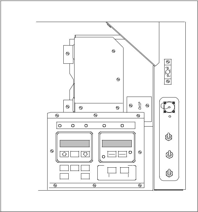
1.2.1 Micro-Link 2 Controller/DataCORDER
The Carrier Transicold Micro-Link 2 Controller (see Figure 1-1) is a custom-designed, microprocessor-based control system which is fitted with a separate DataCORDER module. The DataCORDER consists of:
1.Microprocessor
2.Program memory
3.Data memory
4.Real time clock (RTC)
5.Six thermistor inputs (2 Air Temperature and 4 Cargo Temperature)
6.Two voltage inputs
7.Four status LED’s
8.Two communication ports (serial)
9.Power supply (optional battery pack)
CONTROLLER
DataCORDER
Figure 1-1. Micro-Link 2 Controller and DataCORDER
62-02575-07 |
1-2 |

1.2.2 Micro-Link 2i Controller/DataCORDER
The Micro-Link 2i Controller is an integrated Controller and DataCORDER assembly, but is otherwise identical to the Micro-Link 2 Controller. Scroll compressor units are also fitted with a controller Expansion Module located next to the Controller/DataCORDER.
CONTROLLER/DataCORDER |
EXPANSION MODULE |
(Scroll Compressor Units Only) |
Figure 1-2. Micro-Link 2i Controller/DataCORDER |
1-3 |
62-02575-07 |
1.2.3 Micro-Link 1 Controller/DataCORDER
The Carrier Transicold Micro-Link 1 Controller (see Figure 1-3) predates the Micro-Link 2 Controller. Micro-Link 1 units with the DataCORDER option are equipped with a DataCORDER that is an integral part of the Controller. Interrogation of Micro-Link 1 and Micro-Link 2 Controllers will have some differences.
Figure 1-3. Micro-Link 1 Controller
62-02575-07 |
1-4 |
1.2.4 DataCORDER Capabilities (Micro-Link 2 and Micro-Link 2i only)
The Carrier DataCORDER is a flexible recording device with the following capabilities: a. Sensors
Up to six thermistor temperature probes can be connected directly to the DataCORDER. These probes are referred to as:
1.Supply
2.Return
3.USDA 1
4.USDA 2
5.USDA 3
6.Auxiliary Cargo Probe
On separate DataCORDER modules (Micro-Link 2 only) there are also two 0-5vdc inputs available for future expansion. In addition to these inputs, an additional eight sensors connected to the refrigeration or controlled atmosphere controllers can be recorded.
1.This list of sensors includes:
2.Humidity Sensor
3.Controlled Atmosphere Gas Sensors
4.Temperature Controller Probes (including: supply, return, and defrost temperatures)
5.Controller Pressure Sensors
6.Current Sensors
7.Line Voltage Sensor
8.Frequency
NOTE
The supply and return sensors (SRS and RRS) used by the DataCORDER are not the same supply and return sensors (STS and RTS) used by the Controller.
b. Log Interval
Micro-Link DataCORDER’s log data on 60 minute intervals from time of trip start. Micro-Link 2/2i DataCORDER sensors can be recorded at intervals of 15, 30, 60 (default), or 120 minutes. Data is logged on the exact interval, using a precise real time clock (RTC). All clocks are set to Greenwich Mean Time at the factory and all recording is done on the exact interval (at 12:00 for example, rather than 12:03).
NOTE
Unless specified by your customer to set the DataCORDER clocks for another time zone, the clocks should NOT be adjusted.
c. Sensor Recording Format
Sensors can be recorded in a wide variety of formats. A one byte temperature format can be used for compact data storage. A two byte format can be used for high resolution over the entire temperature range.
1.One byte format (default): 0.25 C (.45 F) steps in chilled mode; 0.5 C (.9 F) steps in frozen mode
2.Two byte format: 0 .010 C steps for entire range
d. Sampling Type
1.Averaged (default): shows average of data from every minute over the logging interval.
2.Snapshot: shows snapshot of data at the log interval.
3.USDA: shows snapshot of data at a 60 minute log interval.
1-5 |
62-02575-07 |
1.3 DataCORDER INTERFACE
The DataCORDER is capable of performing the following functions initiated by the DataView Program
1.3.1 Data Extraction a. Daily Header Data
Recorded days are presented in the following format:
1.Day 1 date (month, day, year), sensor data, events, ...
2.Day 2 date (month, day, year), sensor data, events, ...
b. Sensor Data
Sensor data will be read based on either standard or generic configuration. Please refer to separately bound manuals covering the Refrigeration Unit for further explanation of standard and generic configurations, see Table 1-2.
1.3.2 Events
Events will be transmitted to the DataCORDER as specified in Table 1-3, Table 1-4 and Table 1-5. The DataCORDER compacts the events, disposing of repetitive events to save memory space. All events have a time and date stamp.
Table 1-3. Temperature Controller Events
Event |
When Event Occurs |
Data Stored |
Limits |
|
|
|
|
|
|
Set Point Change (SP) |
Whenever the temperature |
New set point; method |
Last 1 per hour, last 6 per |
|
set point changes |
used to change it |
day. |
||
|
||||
|
Whenever a defrost cycle |
Source of initiation (key- |
|
|
Defrost Start (DS) |
is initiated and when the |
pad, communications, tim- |
First 1 per hour, first 10 |
|
system is in defrost mode |
er, or active from previous |
per day. |
||
|
||||
|
at midnight |
day) |
|
|
Defrost End (DE) |
Whenever a defrost cycle |
Source of termination |
Last 1 per hour, last 10 per |
|
is terminated |
(normal, timer, or HTT) |
day |
||
|
||||
|
Whenever Pre-Trip starts |
Source of initiation (key- |
First 1 per hour, first 4 per |
|
Pre-Trip Start (PS) |
pad, communications, or |
|||
or is active at midnight |
day. |
|||
|
active from previous day) |
|||
|
|
|
||
|
|
|
|
|
Pre-Trip End (PE) |
Whenever Pre-Trip com- |
Pass/Fail data for each test |
Last 1 per hour, last 4 per |
|
pletes. |
run since last power up |
day. |
||
|
||||
Dehumidification Start |
Whenever dehumidifica- |
Set point, humidity read- |
First 1 per hour, first 10 |
|
tion is initiated, or is ac- |
ing type (active at mid- |
|||
(DHS) |
per day. |
|||
tive at midnight |
night or normal) |
|||
|
|
|||
|
|
|
|
|
Dehumidification End |
Whenever dehumidifica- |
Set point, humidity read- |
Last 1 per hour, last 10 per |
|
(DHE) |
tion ends |
ing |
day |
|
Humidification Start |
Whenever humidification |
Set point, humidity read- |
First 1 per hour, first 10 |
|
is initiated, or is active at |
ing, method used to cause |
|||
(HS) |
per day. |
|||
midnight or “htESt” is run |
it |
|||
|
|
|||
|
|
|
|
|
Humidification End |
Whenever humidification |
Set point, humidity read- |
Last 1 per hour, last 10 per |
|
(HE) |
ends |
ing |
day |
|
Humidity Set Point |
Whenever humidity set |
New set point, method |
N/A |
|
Change |
point changes |
used to change it |
||
|
||||
|
Case 1: Whenever an |
Case 1: Alarms active dur- |
Case 1: 1 per hour which |
|
|
is a combination of all |
|||
|
alarm changes state |
ing this hour |
alarm events in that hour |
|
Controller Alarm |
|
|
||
|
|
|
||
Case 2: At the end of any |
|
|
||
Activity (AL) |
|
|
||
hour where an alarm active |
Case 2: Currently active |
Case 2: 1 per hour |
||
|
||||
|
during that hour is inactive |
alarms |
||
|
|
|||
|
at the end of the hour |
|
|
|
|
|
|
|
|
Controller S/W Upgrade |
Any change in the Con- |
New software version |
Last 1 per day. |
|
|
troller software revision. |
|
|
|
Container ID Change |
Any time the container ID |
New ID |
Last 1 per day |
|
is changed |
||||
|
|
|
62-02575-07 |
1-6 |
Table 1-3. Temperature Controller Events -- Continued
Event |
|
|
When Event Occurs |
|
Data Sent |
|
Limits |
Trip Start (TS) |
|
Any time trip start is en- |
NA |
|
NA |
||
|
tered |
|
|||||
|
|
|
|
|
|
||
USDA Trip Comment |
|
When entered with |
Up to 80 bytes of custom- |
|
Last 1 per day |
||
|
interrogation device |
er comment data |
|
||||
|
|
|
|
||||
|
|
Any time a Pre-Trip test is |
Pass/Fail for each sub-test, |
|
|
||
Pre-Trip Data |
|
completed and Controller |
and appropriate data points |
|
Unlimited |
||
|
is configured to send indi- |
|
|||||
|
|
for each test |
|
|
|||
|
|
vidual test data |
|
|
|||
|
|
|
|
|
|
||
Economy Mode Start |
|
Any time economy mode |
NA |
|
NA |
||
(ECON_S) |
|
is initiated |
|
||||
|
|
|
|
|
|||
Economy Mode End |
|
Any time economy mode |
NA |
|
NA |
||
(ECON_E) |
|
is terminated. |
|
||||
|
|
|
|
|
|||
ISO Trip Comment |
|
Whenever entered |
Data entered by user |
|
Last 1 per hour, last 1 per |
||
Changed |
|
|
day |
||||
|
|
|
|
|
|
||
Bulb Mode Start |
|
|
|
Evaporator fan speed, |
|
|
|
|
Any time bulb mode starts |
DTT opening temperature, |
|
NA |
|||
(BULB_S) |
|
|
|||||
|
|
|
dehumidification set point |
|
|
||
|
|
|
|
|
|
||
|
|
|
|
|
|
|
|
Bulb Mode End |
|
Any time bulb mode ends |
NA |
|
NA |
||
(BULB_E) |
|
|
|||||
|
|
|
|
|
|
|
|
Controller Configuration |
|
Whenever changed by user |
Configuration information |
|
Last 1 per hour, last 1 per |
||
Change |
|
|
|
|
|
|
day |
Operating Mode Change |
|
Whenever unit changes |
New operating mode |
|
Last 2 per hour, last 24 per |
||
|
|
mode |
|
|
|
day |
|
Power Management |
|
Whenever power manage- |
|
|
|
Last 4 per hour, last 24 per |
|
Start |
|
Power management mode |
|
||||
|
ment starts |
|
day |
||||
(Reciprocating Only) |
|
|
|
|
|||
|
|
|
|
|
|
|
|
|
|
|
|
|
|
|
|
Power Management End |
|
Whenever power manage- |
Method used to end power |
|
Last 4 per hour, last 24 per |
||
(Reciprocating Only) |
|
ment ends |
management |
|
day |
||
Airslide Position |
|
Whenever Makeup Vent |
Source of change com- |
|
Last 1 per hour, last 6 per |
||
Change |
|
|
|||||
|
Slide Position is changed |
mand |
|
day |
|||
(Reciprocating Only) |
|
|
|||||
|
|
|
|
|
|
|
|
|
|
|
|
|
|
|
|
Phase Switching |
|
Whenever Phase Sequence |
Phase switched to correct/ |
|
Last 6 per hour, last 24 per |
||
(Scroll Only) |
|
is Checked |
incorrect |
|
day |
||
|
|
|
Table 1-4 DataCORDER Events |
|
|
||
|
|
|
|
|
|
|
|
Event |
|
When Event Occurs |
|
Data Stored |
|
Limits |
|
|
|
|
|
|
|
|
|
|
|
|
Case 1: Whenever an |
|
Case 1: Alarms active |
|
Case 1: 1 per hour which |
|
|
|
|
|
is a combination of all |
||
|
|
|
alarm changes state |
|
during this hour |
|
|
|
|
|
|
|
events in that hour |
||
|
|
|
|
|
|
|
|
DataCORDER Alarm Ac- |
|
|
|
|
|
|
|
|
Case 2: At the end of any |
|
|
|
|
||
tivity (DAL) |
|
hour where an alarm ac- |
|
Case 2: Currently active |
|
Case 2: 1 per hour |
|
|
|
|
tive during that hour is in- |
|
|
||
|
|
|
active at the end of the |
|
alarms |
|
|
|
|
|
hour |
|
|
|
|
Battery Backup Start |
|
Loss of main power with |
|
NA |
|
NA |
|
(OFFWB) |
|
battery pack present |
|
|
|||
|
|
|
|
|
|||
Battery Backup End |
|
Restoration of AC power |
|
NA |
|
NA |
|
(ONWB) |
|
with battery pack present |
|
|
|||
|
|
|
|
|
|||
Power Loss (OFF) |
|
Loss of AC power with no |
|
NA |
|
NA |
|
|
|
|
battery pack present |
|
|
|
|
1-7 |
62-02575-07 |
Table 1-4 DataCORDER Events -- Continued
Event |
|
When Event Occurs |
|
Data Stored |
|
|
Limits |
|
|
|
Restoration of AC power |
|
|
|
|
|
|
Power ON (ON) |
|
with no battery pack pres- |
NA |
NA |
|
|||
|
|
ent |
|
|
|
|
|
|
Data Retrieval |
|
Extraction of data from |
|
NA |
NA |
|
||
|
the DataCORDER |
|
|
|||||
|
|
|
|
|
|
|
||
Real Time Clock Change |
|
User modifies the real |
|
New Date and Time; Old |
NA |
|
||
|
time clock (RTC) |
|
Date and Time |
|
||||
|
|
|
|
|
|
|||
|
|
Real Time Clock (RTC) |
|
|
Last 1 per hour, last 1 per |
|||
RTC Battery Replaced |
|
battery internal to Data- |
|
NA |
||||
|
|
day |
|
|||||
|
|
CORDER is replaced |
|
|
|
|||
|
|
|
|
|
|
|
||
|
|
|
|
|
|
|
|
|
|
|
DataCORDER attempted |
|
|
|
|
|
|
Controller Not |
|
to communicate with |
|
NA |
NA |
|
||
Responding (NWF) |
|
Controller, but received |
|
|
||||
|
|
|
|
|
|
|||
|
|
no response |
|
|
|
|
|
|
|
|
DataCORDER was able to |
|
|
|
|
||
Controller Responding |
|
establish communications |
NA |
NA |
|
|||
(NWR) |
|
with Controller, after a |
|
|
||||
|
|
|
|
|
|
|||
|
|
failed attempt. |
|
|
|
|
|
|
DataCORDER |
|
Whenever the Data- |
|
|
First 1 per hour, first 1 per |
|||
|
CORDER detects an in- |
|
NA |
|||||
Configuration Reset |
|
|
day |
|
||||
|
valid configuration |
|
|
|
||||
|
|
|
|
|
|
|
||
|
|
|
|
|
|
|
|
|
Probe Calibration |
|
When Calibration offset |
|
NA |
Last 6 per hour, last 24 |
|||
|
values are entered |
|
per day |
|||||
|
|
|
|
|||||
Table 1-5 Controlled Atmosphere (CA) Events Recorded in the DataCORDER |
||||||||
|
|
|
|
|
|
|
|
|
Event |
|
When Event Occurs |
|
|
Data |
|
|
Limits |
|
|
|
|
|
|
|
|
|
CA Communications |
When communication |
|
|
|
|
|
First 1 per hour, first |
|
with the CA controller is |
|
NA |
|
|
||||
Failure |
|
|
|
24 per day |
||||
lost |
|
|
|
|
|
|||
|
|
|
|
|
|
|
||
|
|
|
|
|
|
|
|
|
CA Communications |
When communication |
|
|
|
|
|
Last 1 per hour, first |
|
with the CA controller is |
|
NA |
|
|
||||
Recovery |
|
|
|
24 per day |
||||
regained |
|
|
|
|
|
|||
|
|
|
|
|
|
|
||
|
|
|
|
|
|
|
|
|
CA Set Point Change |
Whenever the O2 or CO2 |
|
O2 set point, CO2 set point |
|
|
Last 1 per hour, last 6 |
||
(CA-SP) |
set point is changed |
|
|
|
per day |
|||
CA Alarm Reset |
Whenever the CA alarm |
|
|
|
|
|
Last 2 per hour, last |
|
list is reset |
|
|
|
|
|
10 per day |
||
|
|
|
|
|
|
|||
|
|
|
|
|
|
|
|
Case 1: 1 per hour |
|
Case 1: Whenever an |
|
Case 1: Alarms active during this |
|
which is a combina- |
|||
|
alarm changes state |
|
hour |
|
|
tion of all events in |
||
CA Alarm Activity |
|
|
|
|
|
|
|
that hour |
Case 2: At the end of any |
|
|
|
|
|
|
||
(CA-AL) |
|
|
|
|
|
|
||
hour where an alarm ac- |
|
|
|
|
|
|
||
|
|
Case 2: Currently active alarms |
|
Case 2: 1 per hour |
||||
|
tive during that hour is |
|
|
|||||
|
inactive at the end of the |
|
|
|
|
|
|
|
|
hour. |
|
|
|
|
|
|
|
CA Pre-Trip Start |
Whenever CA Pre-Trip is |
|
Source (keypad, communica- |
|
|
First 1 per hour, first |
||
(CA-PS) |
initiated, or is active at |
|
tions, or active at midnight) |
|
|
4 per day |
||
midnight |
|
|
|
|||||
|
|
|
|
|
|
|
||
CA Pre-Trip End |
Whenever CA Pre-Trip is |
|
Test data for all CA Pre-Trip tests |
|
Last 1 per hour, first 4 |
|||
(CA-PE) |
completed |
|
run since the last power on. |
|
|
per day |
||
62-02575-07 |
1-8 |
Table 1-5 Controlled Atmosphere (CA) Events Recorded in the DataCORDER -- Continued
Event |
When Event Occurs |
Data |
Limits |
|
|
Whenever O2 Air Cal- |
New calibration value; Result |
Last 2 per hour, last |
|
O2 Air Calibration |
(pass, fail, or low) Source (key- |
|||
ibration is completed |
10 per day |
|||
|
|
pad, communications, or timer) |
|
|
|
Whenever O2 Gas Cal- |
New calibration value; Result |
Last 2 per hour, last |
|
O2 Gas Calibration |
(pass or fail) Source (keypad, |
|||
ibration is completed |
10 per day |
|||
|
|
communications, or timer) |
|
|
|
Whenever CO Zero Cal- |
New calibration value; Result |
Last 2 per hour, last |
|
CO2 Zero Calibration |
2 |
(pass or fail, no gas) Source (key- |
10 per day |
|
ibration is completed |
||||
|
|
pad, communications, or timer) |
|
|
|
Whenever the Tempera- |
Type: normal, or active at mid- |
|
|
Lockout Start |
ture Controller initiates a |
First 1 per hour |
||
night |
||||
|
lockout of CA operation |
|
||
|
|
|
||
|
|
|
|
|
|
Whenever the Tempera- |
|
|
|
Lockout End |
ture Controller enables |
NA |
Last 1 per hour. |
|
|
CA operation. |
|
|
|
CA Configuration |
Any time the CA unit |
Configuration variables |
Last 2 per hour, last |
|
Change |
configuration changes |
10 per day |
||
|
||||
|
|
N2 purity values for last low, me- |
|
|
CA Nitrogen Test |
Any time a nitrogen test |
dium, and high flow tests, and |
Last 2 per hour, last |
|
flags to indicate whether low, |
||||
is completed |
10 per day |
|||
|
medium and high values are in |
|||
|
|
|
||
|
|
range |
|
|
|
Any time ‘‘service the fil- |
Filter hours expired; filter hours |
|
|
|
ter’’ hours or compressor |
reset; compressor hours expired; |
|
|
|
hours expires or is reset, |
|
||
CA Service Activity |
compressor hours reset; O2 sen- |
First 1 per hour |
||
or the O sensor’s life is |
||||
|
detected2to be low, or the |
sor life low; O2 sensor expired; |
|
|
|
O2 sensor is detected re- |
filter, compressor, and total run |
|
|
|
hours |
|
||
|
placed |
|
|
|
CA Software Upgrade |
Any time the CA soft- |
New software version |
Last 1 per day |
|
ware revision changes |
||||
|
|
|
||
|
Any time the CA Con- |
|
|
|
CA Controller Replaced |
troller serial number |
New serial number |
Last 1 per day |
|
|
changes |
|
|
|
Door Lock (CA-DL) |
Any time the CA door is |
NA |
Last 1 per hour |
|
locked by the Controller |
||||
|
|
|
||
|
Any time the CA door is |
|
|
|
Door Unlock (CA-UL) |
unlocked by the Control- |
NA |
Last 1 per hour |
|
|
ler |
|
|
|
Vent Mode Start |
Any time CA vent mode |
NA |
Last 1 per hour |
|
(CA-VS) |
is initiated |
|||
|
|
|||
Vent Mode End |
Any time CA vent mode |
NA |
Last 1 per hour |
|
(CA-VE) |
is terminated |
|||
|
|
1-9 |
62-02575-07 |
1.4 USDA RECORDING
A special type of recording is provided for USDA cold treatment purposes. Cold treatment recording requires that three remote temperature probes are placed in the cargo at various locations. Provision is made to connect these probes to the DataCORDER via receptacles located at the rear left-hand side of the unit. Four (five, on some units) receptacles are provided. Four (three-pin) receptacles are for the probes and one (five pin) receptacle is provided for the Interrogator. All receptacles are sized to accept a Deutsch HD16-5-16S size plug with a tricam coupling locking device. The DataCORDER inputs are designed to accept a two wire thermistor probe.
A label on the back panel of the unit shows which receptacle is used for each probe. The USDA #1, #2 and #3 probes (and possibly the optional Cargo probe) are installed in these receptacles.
The DataCORDER records up to six probe temperatures (supply, return, USDA #1, #2, #3 and an optional cargo probe #4), at the logging interval.
The standard DataCORDER report displays the supply and return air temperatures. The cold treatment report displays USDA #1, #2, #3 and return air temperatures. Cold treatment recording is backed up by a battery so recording can continue if AC power is lost.
NOTE
There may be an additional (3-pin) receptacle for a cargo probe on some units. This should NOT be used for USDA probes.
1.5 RELATIVE HUMIDITY
When the Relative Humidity Set Point mode is activated or de-activated (i.e., Controller function code Cd33 on Micro-Link 2/2i), this status is stored in the DataCORDER memory and reported as an event.
62-02575-07 |
1-10 |

SECTION 2
SYSTEM SETUP
2.1 HARDWARE PLATFORMS SUPPORTED
The DataView Software will run on a variety of DOS based machines. We recommend the use of a desktop or laptop machine with at least 3MB free disk space and a VGA monitor for displaying graphics, for most printing and report generation functions. Other, less capable computers may be used for the actual data extraction.
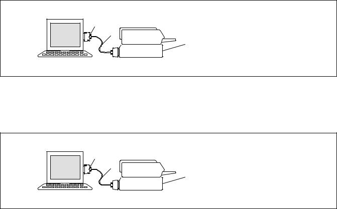
2.2 INTERROGATION CABLES
Cable requirements may differ between interrogation devices. For cable connections see Figure 2-1.
DEUTSCH PLUG
2
DataReader
1
5
9 volt
VEAM PLUG
3 |
Micro-Link 2 |
|
|
6 |
|
|
9 |
DEUTSCH PLUG |
|
H. P. |
|
|
|
|
|
|
PALMTOP |
10 |
|
4 |
7 |
DataReader |
8  Computer Device
1
NOTE
DataReader Kit includes items 1 through 6, item 2 is not sold separately.
1. |
DataReader |
6. |
Software, DataView (DOS) |
2. |
Cable, Download |
7. |
Battery Pack with Charger |
3. |
Cable, Adapter |
8. |
Cable, Battery |
4. |
Cable, Upload |
9. |
Cable Assembly |
5. |
Battery, Alkaline -- 9 Volt |
10. |
Adapter |
Figure 2-1. Communication Cable Connections
2-1 |
62-02575-07 |
2.3 PRINTER SUPPORT
Formatted reports can be generated on the following printers:
1.EPSON 85 dot matrix or compatible (most dot matrix printers will support this format)
2.HP LaserJet or equivalent (Many laser printers will support this format).
For printers that are not compatible with the above printers, select the FILE printer port option in printer setup. This will send the report to an ASCII print file.
2.3.1 PERSONAL COMPUTER PRINTING CABLE CONNECTIONS
After the DataCORDER has been interrogated, the data may be printed from a PC to a parallel or serial printer. Printer cables will differ depending on the type of printer.
a. Parallel Printer
If you are connecting to a parallel printer, a standard Centronics type printer cable may be used (see Figure 2-2). The printer cable connects to the printer port on a PC.
1 |
|
1. |
Portable/Personal |
2 |
|
Computer (Parallel Port) |
|
|
|
||
|
3 |
2. |
Centronics Cable |
|
3. |
Parallel Printer |
|
|
|
Figure 2-2. Parallel Printer Cable Connections
c. Serial Printer
If you are using a Serial Printer, a standard Null-modem type cable may be used (see Figure 2-3). Serial printers with 9-pin serial ports may require a standard 9-socket (female) to 25-pin (male) serial converter.
1 |
|
1. |
Portable/Personal |
2 |
|
Computer (Serial Port) |
|
|
|
||
|
3 |
2. |
Cable |
|
|
(Standard Null--Modem type) |
|
|
|
|
|
|
|
3. |
Parallel Printer |
Figure 2-3. Serial Printer Cable Connections
62-02575-07 |
2-2 |
SECTION 3
DATAVIEW PROGRAM INSTRUCTIONS
NOTE
The following is a copy of the software program at time of printing. If loading only one program (12-00413 reciprocating unit interrogation or 12-00528 scroll unit interrogation program) the program disc instructions may be followed as written. If loading both programs on the same computer, different resident directories must be created Where these differences exist, annotation has been added to the text provided herein.
Refer to the manual Table of Contents for a listing of the following Topics and the material provided under the topic heading.
TOPIC 1 SYSTEM REQUIREMENTS
This section describes the PC and printer system requirements for the DOS DataView interrogator program.
Desktop Computer
1.MS-DOS compatible computer with an 80186 or higher microprocessor.
2.A hard-disk system (Or hard-disk emulation with electronic memory).
3.MS-DOS version 3.3 or higher.
4.A minimum of 640KB free System Memory (RAM).
5.A minimum of 3MB free hard-disk space.
6.One 3.5-inch disk drive. If the system has one diskette drive it will have a drive designator of A. If the system is configured with two diskette drives the second drive will be designated as B.
7.One Serial Port not dedicated to a FAX-Modem.
8.One of the following ports available for a printing;
Serial port Parallel port
Network Connection
9. Serial to serial, serial to parallel, or parallel to parallel printer cable.
HP Palmtop Computer
1.MS-DOS compatible computer with an 80186 or higher microprocessor.
2.MS-DOS version 3.3 or higher.
3.A minimum of 640KB free System Memory (RAM).
4.A minimum of 3MB ROM free space available.
5.One RS-232 serial port.
6.Connectivity Pack to transfer/receive files from a desktop computer to/from the HP Palmtop computer.
7.Serial to serial or serial to parallel printer cable.
Pen-Based Computer
1.MS-DOS compatible computer with an 80186 or higher microprocessor.
2.MS-DOS version 3.3 or higher.
3.A minimum of 640KB free System Memory (RAM).
4.A minimum of 3MB ROM free space available.
5.Optional 3.5 floppy disk drive.
6.One RS-232 serial port.
7.Optional parallel port.
8.Serial to serial, serial to parallel, or parallel to parallel printer cable.
3-1 |
62-02575-07 |
 Loading...