


52C SERIES
OWNER’S MANUAL
PACKAGED TERMINAL AIR CONDITIONERS
AND HEAT PUMPS
7,000-15,000 Btuh
CONTENTS
Page
GENERAL. . . . . . . . . . . . . . . . . . . . . . . . . . . . . . . . . . . . . . . 2
UNIT INSPECTION . . . . . . . . . . . . . . . . . . . . . . . . . . . . . 2,3 FRONT PANEL . . . . . . . . . . . . . . . . . . . . . . . . . . . . . . . . 2
ELECTRICAL DATA. . . . . . . . . . . . . . . . . . . . . . . . . . . . . . 4 ALL UNITS. . . . . . . . . . . . . . . . . . . . . . . . . . . . . . . . . . . . 4 VOLTAGE SUPPLY . . . . . . . . . . . . . . . . . . . . . . . . . . . . . 4
INSTALLATION . . . . . . . . . . . . . . . . . . . . . . . . . . . . . . . .5-7 CHASSIS INSTALLATION . . . . . . . . . . . . . . . . . . . . . . 5
WALL THERMOSTAT INSTALLATION . . . . . . . . . . . 7
OPERATION . . . . . . . . . . . . . . . . . . . . . . . . . . . . . . . . . . .8,9 COMFORT CONTROLS. . . . . . . . . . . . . . . . . . . . . . . . . 8 OPERATING CONTROLS . . . . . . . . . . . . . . . . . . . . . . . 9 OPERATING MODES. . . . . . . . . . . . . . . . . . . . . . . . . . . 9
Page
CARE AND MAINTENANCE . . . . . . . . . . . . . . . . . 10,11
INDOOR-AIR INLET FILTERS . . . . . . . . . . . . . . . . . . 10
EXTERNAL PARTS . . . . . . . . . . . . . . . . . . . . . . . . . . . . 11 INTERNAL PARTS. . . . . . . . . . . . . . . . . . . . . . . . . . . . . 11
PREVENTATIVE MAINTENANCE . . . . . . . . . . . . . . . . 12
TROUBLESHOOTING. . . . . . . . . . . . . . . . . . . . . . . . . . . 13 ACCESSORIES. . . . . . . . . . . . . . . . . . . . . . . . . . . . . . . . . . 14
1•800•894•6449 For Service/ Technical Assistance
52C SERIES
GENERAL
Thank you for choosing Carrier! You can feel confident in your selection because the same pride in craftsmanship and engineering knowledge that goes into Carrier equipment at the Astrodome in Texas, the Sistine Chapel in Rome, the US Capitol Hall of Congress, and thousands of other installations worldwide has gone into the construction of this unit.
The Carrier package terminal air conditioners and heat pumps provide a high standard of quality in performance, workmanship, durability and appearance as they heat and cool the occupied air space year round.
This manual provides information for ease of installation, operation and maintenance of the 52C unit. The following units are covered in this manual (see Figure 1 for additional unit information):
52CE 60 Hz cooling with electric heat units
52CQ 60 Hz cooling, electric heat, and heat pump units
All models are designed for through-the-wall installation. Separate installation instructions are included with all accessory components. See Accessories section on page 14 for complete listing of accessories.
MODEL |
|
52CQA312301AA |
|
|
|
||||||||
|
|
|
|
|
|
|
|
|
|
|
|||
SERIAL |
0201X11520 |
|
|
|
|
||||||||
|
|
|
|
|
|
|
|
|
|
|
|||
DATE OF MFG. |
01/12/2001 |
|
|
|
|||||||||
VOLT RANGE |
187-253 |
|
|
|
|
||||||||
|
|
|
|
|
|
|
|
|
|
|
|||
VOLTS |
230/208 |
|
|
|
|
|
|
||||||
PH |
1 |
|
|
|
|
|
|
HZ |
|
60 |
|
|
|
MIN CKT AMPACITY |
17.9 |
|
|||||||||||
|
|
|
|
|
|
|
|
|
|
|
|
||
R-22 OZ |
34 |
|
|
|
|
|
|
|
|
||||
DESIGN PSIG 350 HIGH SIDE, 150 LOW SIDE |
|||||||||||||
|
|
|
|
|
|
|
|
|
|
|
|
|
|
|
|
|
|
|
COOLING |
|
|
|
|||||
BTU/HR |
12,00/11,900 |
|
|
|
|
|
|||||||
AMPS |
5.8/6.2 |
|
|
|
|
|
|
|
|||||
|
|
|
|
|
|
|
|
|
|
|
|||
WATTS |
1333/1311 |
|
|
|
|
|
|
||||||
EER |
|
|
10.1/10.1 |
|
|
|
|
|
|
||||
COMP |
RLA |
|
70 |
|
|
|
|
|
|||||
|
|
|
|
|
|
|
|
|
|
|
|||
LRA |
|
33.2 |
|
|
|
|
|
||||||
|
|
|
|
|
|
|
|
|
|||||
FAN |
FLA |
|
1.0/0.8 |
|
|
|
|
||||||
MOTOR |
|
HP |
|
1/8 |
|
|
|
|
|
||||
|
|
|
|
|
|
|
|
|
|
|
|
|
|
|
|
|
|
|
|
|
HEATING |
|
|
|
|||
BTU/HR |
10,800/10,700 |
|
|
|
|||||||||
|
|
|
|
|
|
|
|
|
|
|
|||
AMPS |
15.8/14.5 |
|
|
|
|
|
|
||||||
|
|
|
|
|
|
|
|
|
|
|
|||
WATTS |
3600/3025 |
|
|
|
|
|
|||||||
COP |
|
|
3.0/3.0 |
|
|
|
|
|
|
||||
HEATER |
AMPS |
14.8/13.7 |
|
|
|
||||||||
|
|
|
|
|
|
|
|
|
|
|
|||
WATTS |
3400/2850 |
|
|
||||||||||
|
|
|
|
|
|||||||||
BTU/HR |
WATER |
|
|
|
|
||||||||
|
|
|
|
|
|
|
|
|
|
|
|||
|
|
|
STEAM |
|
|
|
|
||||||
|
|
|
|
|
|
|
|
|
|
||||
|
|
|
|
|
AMP |
CANADIAN INSTALLATION |
|||||||
USE |
20 |
|
|
||||||||||
|
|
|
|
|
|
|
|
MAX FUSE |
MAX BREAKER |
||||
TIME DELAY FUSE |
|
|
|
|
|
|
|||||||
OR HACR TYPE |
20 |
|
AMP |
|
20 |
AMP |
|||||||
CIRCUIT BREAKER |
|
|
|
|
|
|
|||||||
|
|
|
|
|
|
||||||||
|
|
|
|
|
|
|
|
|
|
|
|
|
|
|
|
|
|
|
|
|
|
|
|
|
|
|
|
|
|
|
|
|
|
|
|
|
|
|
|
|
|
|
|
|
|
|
|
|
|
|
|
|
|
|
|
|
|
|
|
|
|
|
|
|
|
|
|
|
|
|
|
|
|
|
|
|
|
|
|
|
|
|
|
|
|
|
|
|
|
|
|
|
|
|
|
|
|
|
|
|
|
|
|
|
|
|
|
|
|
|
|
|
|
|
|
|
|
|
|
|
|
|
|
|
|
|
|
|
|
|
|
|
|
|
|
|
|
|
|
FIGURE 1 — SAMPLE DATA INFORMATION PLATE
UNIT INSPECTION
Examine unit for damage incurred during shipment. File a claim immediately with the transit company if damage is found.
The data information plate (Figure 1) lists the model number, voltage ranges, and other important electrical information about this product. Reading and understanding this material is important for proper use of this unit. To access the information plate, the front panel must be removed; see Figure 2.
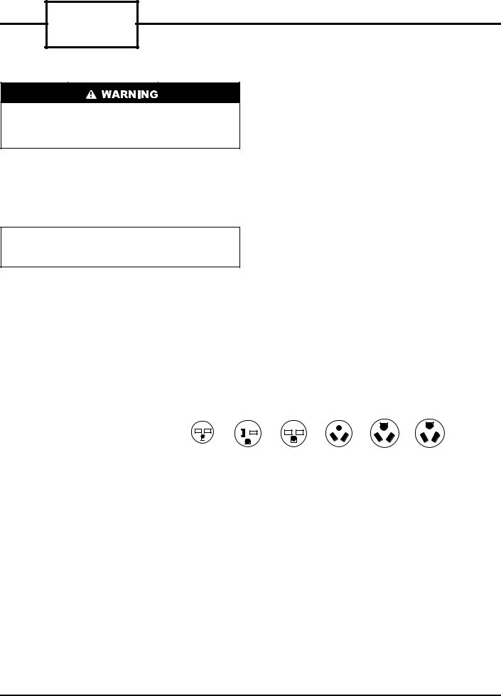
FRONT PANEL
To remove the front panel:
1.Grasp panel firmly near bottom of both sides.
2.Pull panel forward then upward to release magnetic latches and partition hooks.
NOTE: Front panel may be secured to chassis with
2 screws located behind indoor air inlet filters. In order to remove these screws, the filters must be removed first. Refer to page 10 in this manual for instructions on removing indoor air inlet filters.
IMPORTANT: The front panel has to be off the unit to complete future checks and installation procedures. Do not reinstall front panel at this time.
Using Figures 1 and 3 as reference, verify that the packaged terminal product ordered will operate properly in your facility. If you do not understand the information given or have questions about the product, please call your local dealer or distributor.
FIGURE 2 — REMOVING FRONT PANEL
Replacement Package Terminal Air Conditioner, CLASSIFIED BY UNDERWRITERS LABORATORIES INC., AS TO ELECTRIC SHOCK, FIRE AND CASUALTY HAZARDS ONLY. FOR FIELD INSTALLATION WITH EXISTING WALL SLEEVES, OUTDOOR LOUVERS, AND INDOOR PANELS AS SPECIFIED ON THE PRODUCT.
2

52 CE A 3 12 3 0 1 AA
Series Designation
PTAC (Packaged Terminal Air Conditioner)
CE – Cooling with Electric Heat CQ – Heat Pump
Latest Revision
A – Z
Electric Heater Size
2 – 2.3 kW
3 – 3.4 kW
5 – 5.0 kW
Cooling Capacity (nominal)
07 – 7,000 Btuh
09 – 9,000 Btuh
12 – 12,000 Btuh
15 – 15,000 Btuh
Chassis Options
AA – Standard
CP – Corrosion Protection RC – Wall Thermostat Control
RP – Wall Thermostat Control with Corrosion Protection
Packaging
1 – Domestic
Non-Performance
Changes 0-9
Electrical Data
3– 230/208-v, 60 Hz
4– 265-v, 60 Hz
FIGURE 3 — MODEL NUMBER NOMENCLATURE
To install the front panel follow the procedure outlined below:
1.Firmly grasp bottom of front panel on both sides.
2.Hold front panel at a 45 degree angle to unit. Be sure front panel is centered with front of unit.
3.Connect top of front panel to partition rail on top of unit.
4.Gently lower front panel onto chassis, ensuring service cord is positioned through front panel slot.
NOTE: Magnets on bottom of front panel will secure front panel to unit.
To install locking feature on front panel be sure front panel is already installed on unit and follow the steps below:
NOTE: Two field-supplied no. 8, 1/2 in. sheet metal screws are required to secure front panel to chassis.
1.Remove both indoor air inlet filters to expose front panel engagement holes. See Figure 4.
2.Secure front panel to chassis by attaching the field-supplied screws into engagement holes. Do not over tighten.
3.Replace both indoor air inlet filters.
NOTE: Front panel alignment may have to be adjusted slightly to line with chassis.
TOP PARTITION
DISCHARGE |
ENGAGEMENT |
FRONT PANEL |
DECK |
HOLE |
SLOT |
FIGURE 4 — FRONT PANEL INSTALLATION
WITH LOCKING FEATURE
3
52C SERIES
ELECTRICAL DATA
ELECTRICAL SHOCK HAZARD
DO NOT alter cord or plug, and DO NOT use an extension cord. Personal injury or damage to the unit may result.
Be sure that your outlet matches the appropriate blade configuration of the supplied plug and that it is within reach of the service cord. A hardwire kit is available as an accessory to change cord-connected units to hardwired units. (See Accessories section, page 14.)
IMPORTANT: All standard cord-connected 265-v units will require a field-installed electrical subbase accessory.
ALL UNITS
■ WIRE SIZE — Use recommended wire size given in Table 1 and install a single branch circuit. All wiring must comply with local and national codes. All units are designed to operate off single branch circuits only.
NOTE: Use copper conductors only.
■ GROUNDING — For safety and protection, the unit is grounded through the service cord plug or through separate ground wire provided on hardwired units. Be sure that the branch circuit or general purpose outlet is grounded.
TABLE 1 — SUGGESTED BRANCH CIRCUIT
WIRE SIZES*
NAMEPLATE AMPS |
AWG WIRE SIZE† |
7.0 to 12 |
14 |
12.1 to 16 |
12 |
16.1 to 24 |
10 |
LEGEND
AWG — American Wire Gage
*Single circuit from main box.
†Based on copper wire at 60 C temperature rating.
VOLTAGE SUPPLY
Check voltage supply at outlet. For satisfactory results, the voltage range must always be within the ranges found on the data information plate (Figure 1).
■ CORD-CONNECTED UNITS — The 250-v fieldsupplied outlet must match the plug for the standard 208/230-v units and be within reach of the service cord. The standard cord-connected 265-v units require an accessory electrical subbase for operation. See Accessories section, page 14, for subbase selection. Refer to Table 2 for proper receptacle and fuse type.
TABLE 2 — RECEPTACLES AND FUSE TYPES — 250,265 VOLTS
RECEPTACLE |
|
|
|
|
|
|
|
|
|
|
|
|
|
|
|
|
|
|
|
|
|
|
|
|
|
|
|
|
|
|
|
|
|
|
|
|
|
|
|
|
|
|
|
|
|
|
|
|
|
|
|
|
|
|
|
|
|
|
|
|
|
|
|
|
|
|
|
|
|
|
|
|
|
|
|
|
|
|
|
|
|
|
|
|
|
|
|
|
|
|
|
|
|
|
|
|
|
|
|
|
|
|
|
|
|
|
|
|
|
|
|
|
|
|
|
|
|
|
|
|
|
|
|
|
|
|
|
|
15 Amps |
20 Amps |
30 Amps |
15 Amps |
20 Amps |
30 Amps |
|||||||||||||||||||||||||
RATED VOLTS |
250 |
|
250 |
|
250 |
|
265 |
265 |
265 |
|
|||||||||||||||||||||
TIME-DELAY TYPE |
15 |
|
20* |
|
30 |
|
15 |
20 |
30 |
|
|
||||||||||||||||||||
FUSE (or HACR Circuit Breaker) |
|
|
|
|
|
||||||||||||||||||||||||||
|
|
|
|
|
|
|
|
|
|
|
|
|
|
|
|
|
|
|
|
|
|
|
|
|
|
|
|
|
|
|
|
LEGEND |
|
|
|
|
|
|
|
|
|
|
|
|
|
|
|
|
|
|
|
|
|
|
|
|
|
|
|
|
|
|
|
HACR — Heating, Air Conditioning, Refrigeration |
|
|
|
|
|
|
|
|
|
|
|
|
|
|
|
|
|
|
|
|
|
|
|
|
|
||||||
*May be used for 15-amp applications if fused for 15 amp. |
|
|
|
|
|
|
|
|
|
|
|
|
|
|
|
|
|
|
|||||||||||||
4

INSTALLATION
CHASSIS INSTALLATION
Units are shipped without a sleeve. In applications where unit is a replacement, it is recommended that a Carrier sleeve be used. The 52C unit can retrofit General Electric, Amana and Trane sleeves/grilles (be sure outdoor grille is installed on the sleeve). A retrofit kit with instructions is included with every unit. See Table 3 for details. Carrier Corporation must approve any other retrofit application. In deep-wall applications, if an existing grille is used on an outdoor wall opening, do not install an additional outdoor grille on unit sleeve.
|
|
|
FOAM STRIP |
FOAM STRIP |
|||||
|
|
|
OR BAFFLE |
OR BAFFLE |
|||||
|
|
|
|
|
|
|
|
|
|
|
|
|
|
|
|
|
|
|
|
|
|
|
|
|
|
|
|
|
|
|
|
|
|
|
|
|
|
|
|
|
|
|
|
|
|
|
|
|
|
|
|
|
|
|
|
|
|
|
|
|
|
|
|
|
|
|
|
|
|
|
|
|
|
|
|
|
|
|
|
Be sure that the foam strips and/or baffles provide a good seal between the grille and condenser coil tube sheets. These foam strips or baffles provide a barrier to separate condenser air from the major components (compressor and fan motor). See Figures 5 to 8.
NOTE: Inspect wall sleeve for any damage or deterioration before installing chassis.
If baffles are not installed properly, loss of performance and premature damage to the major components can result.
FIGURE 5 — OUTDOOR GRILLE
TABLE 3 — RETROFIT WALL SLEEVES
MANUFACTURER* |
WALL SLEEVE PART NUMBER |
|
General Electric |
|
Metal Sleeve RAB71 |
|
Plastic Sleeve RAB77 |
|
|
|
|
Amana |
Metal Sleeve WS900B |
|
Trane |
Metal Sleeve SLV149 |
|
*Retrofit kit is not needed for Carrier or Bryant applications.
INDOOR-AIR |
DISCHARGE WIRE SCREEN |
OUTDOOR |
COIL TUBE |
INLET |
GRILLE |
ORIFICE |
SHEETS |
FILTERS |
|
|
|
FRONT |
INDOOR |
BASEPAN |
OUTDOOR |
WALL |
PANEL |
COIL |
|
GRILLE |
SLEEVE |
FIGURE 6 — 52C UNIT COMPONENTS
5
 Loading...