


Carrier 68RV15103A, 68RV15102A, 68RV14123A, 68RV11302A, 68RV14102A User Manual
...Transport Air Conditioning
|
|
R |
|
|
|
2P |
BLK |
|
BRN |
|
|
1 |
|
|
|
||
|
|
|
|
|
|
2 |
BLU |
|
WHT |
|
|
|
|
|
|
|
|
|
|
|
GRN/YEL |
|
|
|
WHT |
|
|
C |
F |
|
|
|
H |
||
|
|
|
|
||
EVAP. |
|
|
RED RED |
|
BLU |
|
WHT |
|
|
||
|
|
|
|
|
|
|
|
|
R |
|
|
|
|
YEL |
|
PTC |
|
1 |
2 |
C |
BLU |
|
|
|
|
|
|
|
S
SERVICE MANUAL for
MODEL AirV
Rooftop Air Conditioning Systems
T--298 Rev G

SERVICE MANUAL
For
AirV
AIR CONDITIONING AND
HEATING EQUIPMENT
MODELS
68RV11112A
68RV11122A
68RV11302A
68RV14102A
68RV14103A
68RV14113A
68RV14123A
68RV15102A
68RV15103A
SAFETY SUMMARY
GENERAL SAFETY NOTICES
The following general safety notices supplement the specific warnings and cautions appearing elsewhere in this manual. They are recommended precautions that must be understood and applied during operation and maintenance of the equipment covered herein. The general safety notices are presented in the following three sections labeled: First Aid, Operating Precautions and Maintenance Precautions. A listing of the specific warnings and cautions appearing elsewhere in the manual follows the general safety notices.
FIRST AID
An injury, no matter how slight, should never go unattended. Always obtain first aid or medical attention immediately.
OPERATING PRECAUTIONS
Always wear safety glasses.
Keep hands clear of the evaporator blower and condenser fan.
No work should be performed on the unit until all circuit breakers and start--stop switches are turned off, and power supply is disconnected.
Always work in pairs. Never work alone.
In case of severe vibration or unusual noise, stop the unit and investigate.
MAINTENANCE PRECAUTIONS
Beware of unannounced starting of the evaporator blower & condenser fan. Do not remove the ceiling grill assembly or the upper unit cover assembly before turning the power off, and disconnecting the power supply. Before disconnecting, discharge capacitors by shorting across the capacitors terminals. (See Paragraph 3.6.8)
When disassembling wiring, use numbered stickers to identify wire leads and terminals. This aids in quick, accurate reassembly.
Be sure power is turned off before working on motors, controllers, or electrical control switches. Tag any circuit breakers and power supply to prevent accidental energizing of circuits.
Do not bypass any electrical safety devices, e.g. bridging an overload, or using any sort of jumper wires. Problems with the system should be diagnosed and any necessary repairs must be performed by qualified service personnel.
In case of electrical fire, open circuit switch and extinguish with CO2 (never use water).
Use dry nitrogen to pressurize the system for leak checking. Be careful not to exceed 150 psig test pressure in the hermetic compressor.
Coil fins are sharp. Use care when removing the cover form the base pan to avoid personal injury.
Oil vapor in piping stubs can ignite from torch flame and cause serious injury. Exercise extreme care when brazing, and keep brazing cloth and fire extinguisher handy for emergency use.
Disconnect power to the AirV unit before checking the capacitor.
10/09 |
Safety-- i |
T-298 |

SPECIFIC WARNING AND CAUTION STATEMENTS
The statements listed below are applicable to the refrigeration unit and appear elsewhere in this manual. These recommended precautions must be understood and applied during operation and maintenance of the equipment covered herein.
SPECIFIC WARNINGS AND CAUTIONS
 WARNING
Be sure to observe warnings listed in the safety summary in the front of this manual before performing maintenance on the AirV system
 WARNING
Before working on the unit be sure to first disconnect all electric power to the unit to avoid the possibility of electrical shock and personal injury. Before disconnecting, discharge capacitors by shorting across the capacitors terminals (Refer to paragraph 3.6.8)
 WARNING
Shield coils with cardboard to protect hands against injury from sharp metal edges when removing compressor and other components.
 WARNING
Oil vapor in piping stubs can ignite from torch flame and cause serious injury. Exercise extreme care when brazing, and keep brazing cloth and fire extinguisher handy for emergency use.
 WARNING
Disconnect power to the AirV unit before checking the capacitor.
 WARNING
Do not touch the metal of the screwdriver when discharging the capacitor. You could receive a shock.
 WARNING
Before installing thermostat, turn off all power to unit. There may be more than one power disconnect. Electrical shock can cause personal injury or death.
 CAUTION
In order for the AirV systems to operate efficiently, a dedicated 115 Volt 20 Amp power connection is required.
T--298 |
Safety-- ii |
10/09 |

 CAUTION
Do not use carbon tetrachloride, solvents, or waxes containing solvents to clean plastic sections.
 CAUTION
Coil fins are sharp. Use care when removing the cover form the base pan to avoid personal injury.
 CAUTION
The change from Fahrenheit to Celsius will be permanent. It cannot be changed back to Fahrenheit.
 CAUTION
When re--assembling, ensure the battery springs are correctly placed in the battery spring holders.
 CAUTION
Improper wiring or installation may damage thermostat. Wiring must conform to local and national electrical codes.
10/09 |
Safety--iii |
T-298 |
TABLE OF CONTENTS
PARAGRAPH NUMBER |
Page |
|
SPECIFIC WARNING AND CAUTION STATEMENTS . . . . . . . . . . . . . . . . . . . . . . . . . . . . . . . . . . . . . . . . . . . |
ii |
|
SPECIFIC WARNINGS AND CAUTIONS . . . . . . . . . . . . . . . . . . . . . . . . . . . . . . . . . . . . . . . . . . . . . . . . . . . . . . |
ii |
|
DESCRIPTION . . . . . . . . . . . . . . . . . . . . . . . . . . . . . . . . . . . . . . . . . . . . . . . . . . . . . . . . . . . . . . . . . . . . . . . . . . . . . . . |
1--1 |
|
1.1 |
INTRODUCTION . . . . . . . . . . . . . . . . . . . . . . . . . . . . . . . . . . . . . . . . . . . . . . . . . . . . . . . . . . . . . . . . . . . . . |
1--1 |
1.2 |
SERIAL NUMBER IDENTIFICATION . . . . . . . . . . . . . . . . . . . . . . . . . . . . . . . . . . . . . . . . . . . . . . . . . . . . |
1--1 |
1.3 |
DESIGN CHANGE DESCRIPTIONS . . . . . . . . . . . . . . . . . . . . . . . . . . . . . . . . . . . . . . . . . . . . . . . . . . . . |
1--1 |
1.4 |
SYSTEM (UNIT) INSTALLED DIMENSIONS . . . . . . . . . . . . . . . . . . . . . . . . . . . . . . . . . . . . . . . . . . . . . |
1--9 |
1.5 |
SERIAL NUMBER LOCATIONS . . . . . . . . . . . . . . . . . . . . . . . . . . . . . . . . . . . . . . . . . . . . . . . . . . . . . . . . |
1--14 |
1.6 |
AirV SYSTEM COMPONENT SPECIFICATIONS . . . . . . . . . . . . . . . . . . . . . . . . . . . . . . . . . . . . . . . . . |
1--15 |
1.6.1 Refrigerant Charge . . . . . . . . . . . . . . . . . . . . . . . . . . . . . . . . . . . . . . . . . . . . . . . . . . . . . . . . . . . . . . . . |
1--15 |
|
1.6.2 Compressor -- 115 Volts, 60 Cycles, 1 Phase . . . . . . . . . . . . . . . . . . . . . . . . . . . . . . . . . . . . . . . . . |
1--15 |
|
1.6.3 Compressor -- 220 Volts, 50 Cycles, 1 Phase . . . . . . . . . . . . . . . . . . . . . . . . . . . . . . . . . . . . . . . . . |
1--15 |
|
1.6.4 Thermostat Range (All Free Blow Units) . . . . . . . . . . . . . . . . . . . . . . . . . . . . . . . . . . . . . . . . . . . . . . |
1--15 |
|
1.6.5 Return Air Sensor (Thermistor) . . . . . . . . . . . . . . . . . . . . . . . . . . . . . . . . . . . . . . . . . . . . . . . . . . . . . . |
1--15 |
|
1.6.6 Heat Pump Sensors (Thermistors) . . . . . . . . . . . . . . . . . . . . . . . . . . . . . . . . . . . . . . . . . . . . . . . . . . . |
1--15 |
|
1.7 |
START--UP . . . . . . . . . . . . . . . . . . . . . . . . . . . . . . . . . . . . . . . . . . . . . . . . . . . . . . . . . . . . . . . . . . . . . . . . . . |
1--15 |
1.8 |
Dry Mode Function . . . . . . . . . . . . . . . . . . . . . . . . . . . . . . . . . . . . . . . . . . . . . . . . . . . . . . . . . . . . . . . . . . . . |
1--15 |
1.9 |
REFRIGERANT CYCLE--STANDARD SYSTEM . . . . . . . . . . . . . . . . . . . . . . . . . . . . . . . . . . . . . . . . . . |
1--15 |
1.10 |
REFRIGERANT CYCLE -- HEAT PUMP . . . . . . . . . . . . . . . . . . . . . . . . . . . . . . . . . . . . . . . . . . . . . . . . . |
1--16 |
1.10.1 Cooling . . . . . . . . . . . . . . . . . . . . . . . . . . . . . . . . . . . . . . . . . . . . . . . . . . . . . . . . . . . . . . . . . . . . . . . . . . |
1--16 |
|
1.10.2 Heating . . . . . . . . . . . . . . . . . . . . . . . . . . . . . . . . . . . . . . . . . . . . . . . . . . . . . . . . . . . . . . . . . . . . . . . . . . |
1--17 |
|
1.11 |
FREQUENTLY ASKED QUESTIONS AND ANSWERS . . . . . . . . . . . . . . . . . . . . . . . . . . . . . . . . . . . . |
1--17 |
TROUBLESHOOTING . . . . . . . . . . . . . . . . . . . . . . . . . . . . . . . . . . . . . . . . . . . . . . . . . . . . . . . . . . . . . . . . . . . . . . . . . |
2--1 |
|
2.1 |
NO POWER TO UNIT . . . . . . . . . . . . . . . . . . . . . . . . . . . . . . . . . . . . . . . . . . . . . . . . . . . . . . . . . . . . . . . . . |
2--1 |
2.2 |
DUCTED UNIT WILL NOT OPERATE . . . . . . . . . . . . . . . . . . . . . . . . . . . . . . . . . . . . . . . . . . . . . . . . . . . |
2--1 |
2.3 |
DUCTED UNIT WILL NOT COOL . . . . . . . . . . . . . . . . . . . . . . . . . . . . . . . . . . . . . . . . . . . . . . . . . . . . . . . |
2--1 |
2.4 |
COMPRESSOR POWER SUPPLY OPEN . . . . . . . . . . . . . . . . . . . . . . . . . . . . . . . . . . . . . . . . . . . . . . . |
2--1 |
2.5 |
COMPRESSOR RUNS BUT CYCLES, FAN OPERATING ERRATICALLY . . . . . . . . . . . . . . . . . . . . |
2--1 |
2.6 |
CYCLES ON COMPRESSOR OVERLOAD . . . . . . . . . . . . . . . . . . . . . . . . . . . . . . . . . . . . . . . . . . . . . . |
2--2 |
2.7 |
INSUFFICIENT COOLING, COOLING AIR NOT ADEQUATE . . . . . . . . . . . . . . . . . . . . . . . . . . . . . . |
2--2 |
2.8 |
CONDENSER AIR NOT ADEQUATE . . . . . . . . . . . . . . . . . . . . . . . . . . . . . . . . . . . . . . . . . . . . . . . . . . . . |
2--2 |
2.9 |
INSUFFICIENT COOLING . . . . . . . . . . . . . . . . . . . . . . . . . . . . . . . . . . . . . . . . . . . . . . . . . . . . . . . . . . . . . |
2--2 |
2.10 |
COMPRESSOR FLOODING . . . . . . . . . . . . . . . . . . . . . . . . . . . . . . . . . . . . . . . . . . . . . . . . . . . . . . . . . . . |
2--2 |
2.11 |
HEATER CYCLES ON LIMIT SWITCH (HEAT/ COOL VERSION ONLY) . . . . . . . . . . . . . . . . . . . . . |
2--2 |
2.12 |
AIR SWEEP NOT WORKING (FREE BLOW VERSION ONLY) . . . . . . . . . . . . . . . . . . . . . . . . . . . . . |
2--2 |
2.13 |
WATER LEAKAGE . . . . . . . . . . . . . . . . . . . . . . . . . . . . . . . . . . . . . . . . . . . . . . . . . . . . . . . . . . . . . . . . . . . . |
2--2 |
2.14 |
INADEQUATE HEAT (FREE--BLOW HEAT ONLY) . . . . . . . . . . . . . . . . . . . . . . . . . . . . . . . . . . . . . . . . |
2--3 |
2.15 |
INADEQUATE HEAT (HEAT--PUMP) . . . . . . . . . . . . . . . . . . . . . . . . . . . . . . . . . . . . . . . . . . . . . . . . . . . . |
2--3 |
10/09 |
i |
T--298 |
TABLE OF CONTENTS - Continued:
SERVICE AND MAINTENANCE . . . . . . . . . . . . . . . . . . . . . . . . . . . . . . . . . . . . . . . . . . . . . . . . . . . . . . . . . . . |
. . . . . 3--1 |
||
3.1 |
PREVENTATIVE MAINTENANCE . . . . . . . . . . . . . . . . . . . . . . . . . . . . . . . . . . . . . . . . . . . . . . . . . |
. . . . . 3--1 |
|
3.2 |
OPERATING INSTRUCTIONS . . . . . . . . . . . . . . . . . . . . . . . . . . . . . . . . . . . . . . . . . . . . . . . . . . . . |
. . . . . 3--1 |
|
3.3 |
SERVICE -- GENERAL . . . . . . . . . . . . . . . . . . . . . . . . . . . . . . . . . . . . . . . . . . . . . . . . . . . . . . . . . . . |
. . . . . 3--1 |
|
3.4 CEILING UNIT -- FREE BLOW SYSTEMS . . . . . . . . . . . . . . . . . . . . . . . . . . . . . . . . . . . . . . . . . . |
. . . . . 3--1 |
||
|
3.4.1 |
Filter Removal . . . . . . . . . . . . . . . . . . . . . . . . . . . . . . . . . . . . . . . . . . . . . . . . . . . . . . . . . . . . . . . |
. . . . . 3--1 |
|
3.4.2 |
Ceiling Grill Removal . . . . . . . . . . . . . . . . . . . . . . . . . . . . . . . . . . . . . . . . . . . . . . . . . . . . . . . . . |
. . . . . 3--2 |
|
3.4.3 |
Ceiling Panel Removal . . . . . . . . . . . . . . . . . . . . . . . . . . . . . . . . . . . . . . . . . . . . . . . . . . . . . . . . |
. . . . . 3--2 |
|
3.4.4 |
Master Control Switch . . . . . . . . . . . . . . . . . . . . . . . . . . . . . . . . . . . . . . . . . . . . . . . . . . . . . . . . |
. . . . . 3--2 |
|
3.4.5 |
Air Sweep Switch Removal . . . . . . . . . . . . . . . . . . . . . . . . . . . . . . . . . . . . . . . . . . . . . . . . . . . . |
. . . . . 3--2 |
|
3.4.6 |
Indoor Thermostat Removal . . . . . . . . . . . . . . . . . . . . . . . . . . . . . . . . . . . . . . . . . . . . . . . . . . . |
. . . . . 3--3 |
|
3.4.7 |
Air Sweep Removal . . . . . . . . . . . . . . . . . . . . . . . . . . . . . . . . . . . . . . . . . . . . . . . . . . . . . . . . . . |
. . . . . 3--3 |
|
3.4.8 |
Heat Strip Assembly Removal . . . . . . . . . . . . . . . . . . . . . . . . . . . . . . . . . . . . . . . . . . . . . . . . . |
. . . . . 3--3 |
3.5 |
CEILING UNIT -- DUCTED SYSTEMS . . . . . . . . . . . . . . . . . . . . . . . . . . . . . . . . . . . . . . . . . . . . . . |
. . . . . 3--4 |
|
|
3.5.1 |
Filter Removal . . . . . . . . . . . . . . . . . . . . . . . . . . . . . . . . . . . . . . . . . . . . . . . . . . . . . . . . . . . . . . . |
. . . . . 3--4 |
|
3.5.2 |
Ceiling Grill Removal . . . . . . . . . . . . . . . . . . . . . . . . . . . . . . . . . . . . . . . . . . . . . . . . . . . . . . . . . |
. . . . . 3--4 |
|
3.5.3 |
Control Box Assembly Removal . . . . . . . . . . . . . . . . . . . . . . . . . . . . . . . . . . . . . . . . . . . . . . . . |
. . . . . 3--4 |
|
3.5.4 |
Main PCB Board Removal . . . . . . . . . . . . . . . . . . . . . . . . . . . . . . . . . . . . . . . . . . . . . . . . . . . . . |
. . . . . 3--5 |
|
3.5.5 |
PCB Display Removal . . . . . . . . . . . . . . . . . . . . . . . . . . . . . . . . . . . . . . . . . . . . . . . . . . . . . . . . |
. . . . . 3--5 |
|
3.5.6 |
Fuse Removal . . . . . . . . . . . . . . . . . . . . . . . . . . . . . . . . . . . . . . . . . . . . . . . . . . . . . . . . . . . . . . . |
. . . . . 3--5 |
|
3.5.7 |
Dip Switch Functions . . . . . . . . . . . . . . . . . . . . . . . . . . . . . . . . . . . . . . . . . . . . . . . . . . . . . . . . . |
. . . . . 3--6 |
|
3.5.8 |
Return Air Thermistor . . . . . . . . . . . . . . . . . . . . . . . . . . . . . . . . . . . . . . . . . . . . . . . . . . . . . . . . . |
. . . . . 3--6 |
|
3.5.9 |
Heat Pump Thermistors . . . . . . . . . . . . . . . . . . . . . . . . . . . . . . . . . . . . . . . . . . . . . . . . . . . . . . . |
. . . . . 3--7 |
3.6 SERVICE -- UPPER UNIT -- STANDARD, HC & HP . . . . . . . . . . . . . . . . . . . . . . . . . . . . . . . . . . |
. . . . . 3--8 |
||
|
3.6.1 |
Exterior Cover Removal . . . . . . . . . . . . . . . . . . . . . . . . . . . . . . . . . . . . . . . . . . . . . . . . . . . . . . . |
. . . . . 3--8 |
|
3.6.2 |
Compressor Replacement . . . . . . . . . . . . . . . . . . . . . . . . . . . . . . . . . . . . . . . . . . . . . . . . . . . . . |
. . . . . 3--8 |
|
3.6.3 |
Control Box Assembly Removal . . . . . . . . . . . . . . . . . . . . . . . . . . . . . . . . . . . . . . . . . . . . . . . . |
. . . . . 3--8 |
|
3.6.4 |
Upper Scroll Assembly Removal . . . . . . . . . . . . . . . . . . . . . . . . . . . . . . . . . . . . . . . . . . . . . . . |
. . . . . 3--8 |
|
3.6.5 |
Motor Assembly and Condenser Fan Removal . . . . . . . . . . . . . . . . . . . . . . . . . . . . . . . . . . . |
. . . . . 3--9 |
|
3.6.6 |
Evaporator Blower Wheel Adjustment or Removal . . . . . . . . . . . . . . . . . . . . . . . . . . . . . . . . |
. . . . . 3--10 |
|
3.6.7 |
Air Handling System Removal . . . . . . . . . . . . . . . . . . . . . . . . . . . . . . . . . . . . . . . . . . . . . . . . . |
. . . . . 3--10 |
|
3.6.8 |
Capacitor Troubleshooting . . . . . . . . . . . . . . . . . . . . . . . . . . . . . . . . . . . . . . . . . . . . . . . . . . . . . |
. . . . . 3--10 |
|
3.6.9 |
Capacitor Testing and Replacement . . . . . . . . . . . . . . . . . . . . . . . . . . . . . . . . . . . . . . . . . . . . |
. . . . . 3--11 |
|
3.6.10 |
Positive Temperature Coefficient Thermistor (PTC) (Start Thermistor) Troubleshooting |
. . . . . 3--11 |
|
3.6.11 |
Line Voltage -- 10% . . . . . . . . . . . . . . . . . . . . . . . . . . . . . . . . . . . . . . . . . . . . . . . . . . . . . . . . . . . |
. . . . . 3--11 |
3.7 |
SERVICE -- UPPER UNIT -- LOW PROFILE . . . . . . . . . . . . . . . . . . . . . . . . . . . . . . . . . . . . . . . . |
. . . . . 3--12 |
|
|
3.7.1 |
Exterior Cover Removal . . . . . . . . . . . . . . . . . . . . . . . . . . . . . . . . . . . . . . . . . . . . . . . . . . . . . . . |
. . . . . 3--12 |
|
3.7.2 |
Upper Scroll Assembly Removal . . . . . . . . . . . . . . . . . . . . . . . . . . . . . . . . . . . . . . . . . . . . . . . |
. . . . . 3--12 |
|
3.7.3 |
Condenser Fan Assembly Removal . . . . . . . . . . . . . . . . . . . . . . . . . . . . . . . . . . . . . . . . . . . . . |
. . . . . 3--13 |
|
3.7.4 |
Condenser Motor Removal . . . . . . . . . . . . . . . . . . . . . . . . . . . . . . . . . . . . . . . . . . . . . . . . . . . . |
. . . . . 3--14 |
|
3.7.5 |
Evaporator Motor/Blower Assembly Removal . . . . . . . . . . . . . . . . . . . . . . . . . . . . . . . . . . . . |
. . . . . 3--14 |
|
3.7.6 |
Compressor Replacement . . . . . . . . . . . . . . . . . . . . . . . . . . . . . . . . . . . . . . . . . . . . . . . . . . . . . |
. . . . . 3--15 |
|
3.7.7 |
Capacitor Removal . . . . . . . . . . . . . . . . . . . . . . . . . . . . . . . . . . . . . . . . . . . . . . . . . . . . . . . . . . . |
. . . . . 3--15 |
|
3.7.8 |
Remote Control (Fahrenheit to Celsius) . . . . . . . . . . . . . . . . . . . . . . . . . . . . . . . . . . . . . . . . . |
. . . . . 3--15 |
T--298 |
ii |
10/09 |
|
TABLE OF CONTENTS - Continued:
3.8 THERMOSTAT INSTALLATION AND START--UP INSTRUCTIONS (WALL MOUNTED) . . . . . . . |
3--17 |
||
3.8.1 |
Introduction . . . . . . . . . . . . . . . . . . . . . . . . . . . . . . . . . . . . . . . . . . . . . . . . . . . . . . . . . . . . . . . . . . . . . . |
3--17 |
|
3.8.2 |
Installation . . . . . . . . . . . . . . . . . . . . . . . . . . . . . . . . . . . . . . . . . . . . . . . . . . . . . . . . . . . . . . . . . . . . . . . |
3--17 |
|
3.8.3 |
Thermostat Location . . . . . . . . . . . . . . . . . . . . . . . . . . . . . . . . . . . . . . . . . . . . . . . . . . . . . . . . . . . . . . . |
3--17 |
|
3.8.4 |
Install Thermostat -- 12VDC . . . . . . . . . . . . . . . . . . . . . . . . . . . . . . . . . . . . . . . . . . . . . . . . . . . . . . . . |
3--17 |
|
3.9 |
LCD DISPLAY . . . . . . . . . . . . . . . . . . . . . . . . . . . . . . . . . . . . . . . . . . . . . . . . . . . . . . . . . . . . . . . . . . . . . . . |
3--17 |
|
3.9.1 |
Cool Only Thermostat (Part No. 1110--421) . . . . . . . . . . . . . . . . . . . . . . . . . . . . . . . . . . . . . . . . . . . |
3--17 |
|
3.9.2 |
Heat/Cool Thermostat (Part No. 1110--420) . . . . . . . . . . . . . . . . . . . . . . . . . . . . . . . . . . . . . . . . . . . |
3--17 |
|
3.10 |
SET THERMOSTAT CONFIGURATION . . . . . . . . . . . . . . . . . . . . . . . . . . . . . . . . . . . . . . . . . . . . . . . . . |
3--17 |
|
3.10.1 Enter Configuration Mode . . . . . . . . . . . . . . . . . . . . . . . . . . . . . . . . . . . . . . . . . . . . . . . . . . . . . . . . . . |
3--17 |
||
3.11 |
CHECK THERMOSTAT OPERATION . . . . . . . . . . . . . . . . . . . . . . . . . . . . . . . . . . . . . . . . . . . . . . . . . . . |
3--18 |
|
3.11.1 |
Fan Operation (Cool Only) . . . . . . . . . . . . . . . . . . . . . . . . . . . . . . . . . . . . . . . . . . . . . . . . . . . . . . . . . . |
3--18 |
|
3.11.2 |
Fan Operation (Heat/Cool) . . . . . . . . . . . . . . . . . . . . . . . . . . . . . . . . . . . . . . . . . . . . . . . . . . . . . . . . . |
3--18 |
|
3.11.3 |
Cooling Operation (Cool Only) . . . . . . . . . . . . . . . . . . . . . . . . . . . . . . . . . . . . . . . . . . . . . . . . . . . . . . |
3--18 |
|
3.11.4 |
Cooling Operation (Heat/Cool) . . . . . . . . . . . . . . . . . . . . . . . . . . . . . . . . . . . . . . . . . . . . . . . . . . . . . . |
3--18 |
|
3.11.5 |
Heating Operation (Heat/Cool) . . . . . . . . . . . . . . . . . . . . . . . . . . . . . . . . . . . . . . . . . . . . . . . . . . . . . . |
3--18 |
|
3.12 |
CHECK THERMOSTAT OPERATION . . . . . . . . . . . . . . . . . . . . . . . . . . . . . . . . . . . . . . . . . . . . . . . . . . . |
3--18 |
|
3.12.1 Temperature Display . . . . . . . . . . . . . . . . . . . . . . . . . . . . . . . . . . . . . . . . . . . . . . . . . . . . . . . . . . . . . . . |
3--18 |
||
3.12.2 Timeguard Timer . . . . . . . . . . . . . . . . . . . . . . . . . . . . . . . . . . . . . . . . . . . . . . . . . . . . . . . . . . . . . . . . . . |
3--19 |
||
3.12.3 Cycle Timer . . . . . . . . . . . . . . . . . . . . . . . . . . . . . . . . . . . . . . . . . . . . . . . . . . . . . . . . . . . . . . . . . . . . . . |
3--19 |
||
3.12.4 Minimum On Timer . . . . . . . . . . . . . . . . . . . . . . . . . . . . . . . . . . . . . . . . . . . . . . . . . . . . . . . . . . . . . . . . |
3--19 |
||
3.12.5 Error Messages . . . . . . . . . . . . . . . . . . . . . . . . . . . . . . . . . . . . . . . . . . . . . . . . . . . . . . . . . . . . . . . . . . . |
3--19 |
||
WIRING SCHEMATICS . . . . . . . . . . . . . . . . . . . . . . . . . . . . . . . . . . . . . . . . . . . . . . . . . . . . . . . . . . . . . . . . . . . . . . . . |
4--1 |
||
4.1 |
INTRODUCTION . . . . . . . . . . . . . . . . . . . . . . . . . . . . . . . . . . . . . . . . . . . . . . . . . . . . . . . . . . . . . . . . . . . . . |
4--1 |
|
4.2 |
WALL MOUNTED THERMOSTATS . . . . . . . . . . . . . . . . . . . . . . . . . . . . . . . . . . . . . . . . . . . . . . . . . . . . . |
4--6 |
|
4.3 WALL--MOUNTED SENSOR FOR REMOTE CONTROL . . . . . . . . . . . . . . . . . . . . . . . . . . . . . . . . . . . |
4--6 |
||
LIST OF FIGURES
Figure 1--1 Model/Serial Number Plate (Typical) . . . . . . . . . . . . . . . . . . . . . . . . . . . . . . . . . . . . . . . . . . . . . . . . . . |
1--1 |
||
Figure 1--2 Roof Unit (Standard) Component Identification . . . . . . . . . . . . . . . . . . . . . . . . . . . . . . . . . . . . . . . . . |
1--5 |
||
Figure 1--3 Ceiling Unit Component Identification (Free--Blow) . . . . . . . . . . . . . . . . . . . . . . . . . . . . . . . . . . . . . . |
1--6 |
||
Figure 1--4 Component Identification -- Low Profile -- Upper Unit . . . . . . . . . . . . . . . . . . . . . . . . . . . . . . . . . . . . |
1--7 |
||
Figure 1--5 Component Listing--Ceiling Unit For Ducted Systems . . . . . . . . . . . . . . . . . . . . . . . . . . . . . . . . . . . . |
1--8 |
||
Figure 1--6 |
Unit Dimensions -- Top View -- Upper Unit (Roof) Installed . . . . . . . . . . . . . . . . . . . . . . . . . . . . . . . . |
1--9 |
|
Figure 1--7 |
Unit Dimensions -- Standard -- Side View -- Roof + Ceiling . . . . . . . . . . . . . . . . . . . . . . . . . . . . . . . |
1--10 |
|
Figure 1--8 |
Unit Dimensions -- Low Profile -- Side View -- Roof + Ceiling . . . . . . . . . . . . . . . . . . . . . . . . . . . . . |
1--11 |
|
Figure 1--9 |
Unit Dimensions -- Ceiling Unit -- Bottom View . . . . . . . . . . . . . . . . . . . . . . . . . . . . . . . . . . . . . . . . . . |
1--12 |
|
Figure 1--10 Ducted System Air Flow Arrangement . . . . . . . . . . . . . . . . . . . . . . . . . . . . . . . . . . . . . . . . . . . . . . . . |
1--13 |
||
Figure 1--11 Serial Number Locations (Free--Blow) . . . . . . . . . . . . . . . . . . . . . . . . . . . . . . . . . . . . . . . . . . . . . . . . |
1--14 |
||
Figure 1--12 |
Serial Number Locations (Ducted) . . . . . . . . . . . . . . . . . . . . . . . . . . . . . . . . . . . . . . . . . . . . . . . . . . . |
1--14 |
|
Figure 1--13 |
Refrigerant Flow Schematic (Standard System) . . . . . . . . . . . . . . . . . . . . . . . . . . . . . . . . . . . . . . . |
1--15 |
|
Figure 1--14 |
Refrigerant Flow Schematic -- Heat Pump -- (Cool Mode) . . . . . . . . . . . . . . . . . . . . . . . . . . . . . . . |
1--16 |
|
Figure 1--15 |
Refrigerant Flow Schematic -- Heat Pump -- (Heat Mode) . . . . . . . . . . . . . . . . . . . . . . . . . . . . . . . |
1--17 |
|
10/09 |
iii |
T--298 |
LIST OF FIGURES - Continued:
Figure 3--1 Filter Removal -- Free Blow . . . . . . . . . . . . . . . . . . . . . . . . . . . . . . . . . . . . . . . . . . . . . . . . . . . . . . . . . . |
3--1 |
Figure 3--2 Ceiling Grill -- Free Blow . . . . . . . . . . . . . . . . . . . . . . . . . . . . . . . . . . . . . . . . . . . . . . . . . . . . . . . . . . . . . |
3--2 |
Figure 3--3 Ceiling Panel Assembly . . . . . . . . . . . . . . . . . . . . . . . . . . . . . . . . . . . . . . . . . . . . . . . . . . . . . . . . . . . . . |
3--2 |
Figure 3--4 Ceiling Panel With Heat Option . . . . . . . . . . . . . . . . . . . . . . . . . . . . . . . . . . . . . . . . . . . . . . . . . . . . . . . |
3--2 |
Figure 3--5 Control Box Assembly -- Free Blow . . . . . . . . . . . . . . . . . . . . . . . . . . . . . . . . . . . . . . . . . . . . . . . . . . . |
3--2 |
Figure 3--6 Indoor Thermostat . . . . . . . . . . . . . . . . . . . . . . . . . . . . . . . . . . . . . . . . . . . . . . . . . . . . . . . . . . . . . . . . . . |
3--3 |
Figure 3--7 Air sweep motor . . . . . . . . . . . . . . . . . . . . . . . . . . . . . . . . . . . . . . . . . . . . . . . . . . . . . . . . . . . . . . . . . . . . |
3--3 |
Figure 3--8 Heat Strip Assembly . . . . . . . . . . . . . . . . . . . . . . . . . . . . . . . . . . . . . . . . . . . . . . . . . . . . . . . . . . . . . . . . |
3--3 |
Figure 3--9 Filter Removal -- Ducted Unit . . . . . . . . . . . . . . . . . . . . . . . . . . . . . . . . . . . . . . . . . . . . . . . . . . . . . . . . . |
3--4 |
Figure 3--10 Ceiling Grill -- Ducted . . . . . . . . . . . . . . . . . . . . . . . . . . . . . . . . . . . . . . . . . . . . . . . . . . . . . . . . . . . . . . |
3--4 |
Figure 3--11 Control Box & PCB Cover . . . . . . . . . . . . . . . . . . . . . . . . . . . . . . . . . . . . . . . . . . . . . . . . . . . . . . . . . . |
3--4 |
Figure 3--12 Control Box Assembly -- Ducted . . . . . . . . . . . . . . . . . . . . . . . . . . . . . . . . . . . . . . . . . . . . . . . . . . . . . |
3--5 |
Figure 3--13 Main/Display PCB’s . . . . . . . . . . . . . . . . . . . . . . . . . . . . . . . . . . . . . . . . . . . . . . . . . . . . . . . . . . . . . . . |
3--5 |
Figure 3--14 Dip Switch Function . . . . . . . . . . . . . . . . . . . . . . . . . . . . . . . . . . . . . . . . . . . . . . . . . . . . . . . . . . . . . . . |
3--6 |
Figure 3--15 Cover Assembly -- Standard . . . . . . . . . . . . . . . . . . . . . . . . . . . . . . . . . . . . . . . . . . . . . . . . . . . . . . . . |
3--8 |
Figure 3--16 Control Box . . . . . . . . . . . . . . . . . . . . . . . . . . . . . . . . . . . . . . . . . . . . . . . . . . . . . . . . . . . . . . . . . . . . . . |
3--8 |
Figure 3--17 Control Box Removal . . . . . . . . . . . . . . . . . . . . . . . . . . . . . . . . . . . . . . . . . . . . . . . . . . . . . . . . . . . . . . |
3--8 |
Figure 3--18 Water Cover Removal . . . . . . . . . . . . . . . . . . . . . . . . . . . . . . . . . . . . . . . . . . . . . . . . . . . . . . . . . . . . . |
3--8 |
Figure 3--19 Upper Scroll Assembly . . . . . . . . . . . . . . . . . . . . . . . . . . . . . . . . . . . . . . . . . . . . . . . . . . . . . . . . . . . . . |
3--9 |
Figure 3--20 Motor Assembly . . . . . . . . . . . . . . . . . . . . . . . . . . . . . . . . . . . . . . . . . . . . . . . . . . . . . . . . . . . . . . . . . . . |
3--9 |
Figure 3--21 Spring Clamp Removal . . . . . . . . . . . . . . . . . . . . . . . . . . . . . . . . . . . . . . . . . . . . . . . . . . . . . . . . . . . . |
3--9 |
Figure 3--22 Motor Clip Removal . . . . . . . . . . . . . . . . . . . . . . . . . . . . . . . . . . . . . . . . . . . . . . . . . . . . . . . . . . . . . . . |
3--9 |
Figure 3--23 Condenser Fan Removal . . . . . . . . . . . . . . . . . . . . . . . . . . . . . . . . . . . . . . . . . . . . . . . . . . . . . . . . . . . |
3--10 |
Figure 3--24 Blower Wheel . . . . . . . . . . . . . . . . . . . . . . . . . . . . . . . . . . . . . . . . . . . . . . . . . . . . . . . . . . . . . . . . . . . . . |
3--10 |
Figure 3--25 Condenser With Motor Assembly & Compressor . . . . . . . . . . . . . . . . . . . . . . . . . . . . . . . . . . . . . . |
3--10 |
Figure 3--26 Set--Up For Discharging a Capacitor . . . . . . . . . . . . . . . . . . . . . . . . . . . . . . . . . . . . . . . . . . . . . . . . . |
3--11 |
Figure 3--27 Cover Assembly -- Low Profile . . . . . . . . . . . . . . . . . . . . . . . . . . . . . . . . . . . . . . . . . . . . . . . . . . . . . . |
3--12 |
Figure 3--28 Upper Scroll Assembly Locking Tabs (b.) & Screw Locations (c.) . . . . . . . . . . . . . . . . . . . . . . . . . |
3--12 |
Figure 3--29 Upper Scroll Assembly Keeper Tab Release . . . . . . . . . . . . . . . . . . . . . . . . . . . . . . . . . . . . . . . . . . |
3--12 |
Figure 3--30 Upper Scroll & Control Box Cover Removed . . . . . . . . . . . . . . . . . . . . . . . . . . . . . . . . . . . . . . . . . . |
3--13 |
Figure 3--31 Condenser Fan Assembly& Retaining Ring . . . . . . . . . . . . . . . . . . . . . . . . . . . . . . . . . . . . . . . . . . . |
3--13 |
Figure 3--32 Condenser Fan Motor& Fan Assembly Stop . . . . . . . . . . . . . . . . . . . . . . . . . . . . . . . . . . . . . . . . . . |
3--13 |
Figure 3--33 Condenser Fan Motor& Fan Assembly Tab . . . . . . . . . . . . . . . . . . . . . . . . . . . . . . . . . . . . . . . . . . . |
3--13 |
Figure 3--34 Condenser Motor Ground . . . . . . . . . . . . . . . . . . . . . . . . . . . . . . . . . . . . . . . . . . . . . . . . . . . . . . . . . . |
3--14 |
Figure 3--35 Evaporator Motor Locking Tabs . . . . . . . . . . . . . . . . . . . . . . . . . . . . . . . . . . . . . . . . . . . . . . . . . . . . . |
3--14 |
Figure 3--36 Evaporator Motor/Blower Assembly . . . . . . . . . . . . . . . . . . . . . . . . . . . . . . . . . . . . . . . . . . . . . . . . . |
3--14 |
Figure 3--37 Evaporator Blower Wheel . . . . . . . . . . . . . . . . . . . . . . . . . . . . . . . . . . . . . . . . . . . . . . . . . . . . . . . . . . |
3--15 |
Figure 3--38 Control Box Assembly With Capacitor . . . . . . . . . . . . . . . . . . . . . . . . . . . . . . . . . . . . . . . . . . . . . . . . |
3--15 |
Figure 3--39 Remote Control Components . . . . . . . . . . . . . . . . . . . . . . . . . . . . . . . . . . . . . . . . . . . . . . . . . . . . . . . |
3--16 |
T--298 |
iv |
10/09 |
LIST OF FIGURES - Continued:
Figure 3--40 Remote Control PCB (FR9 Location) . . . . . . . . . . . . . . . . . . . . . . . . . . . . . . . . . . . . . . . . . . . . . . . . . |
3--16 |
||
Figure 3--41 Wall Thermostat Wiring Diagram -- Cool Only Model . . . . . . . . . . . . . . . . . . . . . . . . . . . . . . . . . . . |
3--19 |
||
Figure 3--42 Wall Thermostat Wiring Diagram -- Heat/Cool Model . . . . . . . . . . . . . . . . . . . . . . . . . . . . . . . . . . . |
3--20 |
||
Figure 3--43 (Optional) Wall Thermostat Wiring Diagram -- Heat/Cool Model . . . . . . . . . . . . . . . . . . . . . . . . . . |
3--21 |
||
Figure 4--1 Upper Unit Schematic -- Standard & HC . . . . . . . . . . . . . . . . . . . . . . . . . . . . . . . . . . . . . . . . . . . . . . . |
4--1 |
||
Figure 4--2 Upper Unit Schematic -- Low Profile . . . . . . . . . . . . . . . . . . . . . . . . . . . . . . . . . . . . . . . . . . . . . . . . . . . |
4--1 |
||
Figure 4--3 Ceiling Unit Schematic -- Cooling Only . . . . . . . . . . . . . . . . . . . . . . . . . . . . . . . . . . . . . . . . . . . . . . . . |
4--2 |
||
Figure 4--4 Ceiling Unit Schematic -- Heat/Cool . . . . . . . . . . . . . . . . . . . . . . . . . . . . . . . . . . . . . . . . . . . . . . . . . . . |
4--2 |
||
Figure 4--5 Ceiling Unit, Standard -- Ducted . . . . . . . . . . . . . . . . . . . . . . . . . . . . . . . . . . . . . . . . . . . . . . . . . . . . . . |
4--2 |
||
Figure 4--6 |
Heat Pump -- Upper Unit -- Free Blow . . . . . . . . . . . . . . . . . . . . . . . . . . . . . . . . . . . . . . . . . . . . . . . . . |
4--3 |
|
Figure 4--7 |
Heat Pump -- Ceiling Unit -- Free Blow . . . . . . . . . . . . . . . . . . . . . . . . . . . . . . . . . . . . . . . . . . . . . . . . |
4--3 |
|
Figure 4--8 |
Heat Pump -- Upper Unit -- Standard -- Ducted . . . . . . . . . . . . . . . . . . . . . . . . . . . . . . . . . . . . . . . . . |
4--4 |
|
Figure 4--9 |
Heat Pump -- Upper Unit -- Low Profile -- Ducted . . . . . . . . . . . . . . . . . . . . . . . . . . . . . . . . . . . . . . . . |
4--4 |
|
Figure 4--10 Heat Pump -- Ceiling Unit -- Ducted . . . . . . . . . . . . . . . . . . . . . . . . . . . . . . . . . . . . . . . . . . . . . . . . . . |
4--5 |
||
Figure 4--11 |
Ceiling Unit -- Wall Thermostat -- Cool Only -- Ducted & Free Blow . . . . . . . . . . . . . . . . . . . . . . . |
4--5 |
|
Figure 4--12 |
Ceiling Unit -- Wall Thermostat -- Heat/Cool -- Free Blow . . . . . . . . . . . . . . . . . . . . . . . . . . . . . . . |
4--6 |
|
LIST OF TABLES
Table 1--1 Model Chart . . . . . . . . . . . . . . . . . . . . . . . . . . . . . . . . . . . . . . . . . . . . . . . . . . . . . . . . . . . . . . . . . . . . . . . . . |
1--2 |
|
Table 1--2 |
MODEL CHART . . . . . . . . . . . . . . . . . . . . . . . . . . . . . . . . . . . . . . . . . . . . . . . . . . . . . . . . . . . . . . . . . . . . . |
1--3 |
Table 1--3 ADDITIONAL SUPPORT MANUALS . . . . . . . . . . . . . . . . . . . . . . . . . . . . . . . . . . . . . . . . . . . . . . . . . . . |
1--4 |
|
Table 2--1 |
System Self--diagnostics Function (Ducted Remote) . . . . . . . . . . . . . . . . . . . . . . . . . . . . . . . . . . . . . . |
2--4 |
Table 3--1 |
Resistance--Temperature Coefficient . . . . . . . . . . . . . . . . . . . . . . . . . . . . . . . . . . . . . . . . . . . . . . . . . . . . |
3--6 |
Table 3--2 |
Resistance--Temperature Coefficient (IDC -- ODA -- ODC) . . . . . . . . . . . . . . . . . . . . . . . . . . . . . . . . . |
3--7 |
10/09 |
v |
T--298 |
SECTION 1 DESCRIPTION
1.1 INTRODUCTION
This manual contains service instructions and electrical data for the AirV, Carrier Transport Air Conditioning’s Recreational Vehicle air conditioning unit.
The AirV units are two piece systems, consisting of the Upper Unit and the Ceiling unit. The Upper Unit contains the refrigeration system while the Ceiling Unit contains the controls and vents. The Ceiling Units are available in a free--blow or ducted configuration.
The free--blow units (see Figure 1--2) deliver air to the vehicle by means of front and rear end vents and one downward vent (air shower). The vents may all be opened or closed to direct air as desired. The front and rear vents are fitted with motorized dampers that oscillates to produce an “air--sweep” effect. These units may be fitted with optional electric heat.
The ducted units (see Figure 1--5 and Figure 1--10) deliver air through ducting built in the vehicle ceiling. These units are fitted with a 12 VDC microprocessor control system, a display panel (PCB display) and a remote controller. These units may be wired to provide thermostatic control of the vehicle furnace.
Carrier’s AirV air conditioning models include cooling only units, heating/cooling units, and heat pump units. The cooling only units are available with free blow or ducted air delivery. Cooling units with heat strips are available for free blow only.
Operation of the AirV units is controlled automatically by the temperature controller (thermostat), which maintains the vehicle’s interior temperature at the desired set point. Free Blow, cool--only units are available with a wall mounted thermostat.
Table 1--1 lists Upper Unit AirV model numbers and descriptions. Table 1--2 lists Ceiling Unit model numbers and descriptions. Table 1--3 lists additional support manuals that are available.
1.2 SERIAL NUMBER IDENTIFICATION
Separate part numbers and serial numbers are provided for the upper and lower unit assemblies The numbers may be found on plates readable from inside the vehicle, See Figure 1--11 or Figure 1--12.
The first two numbers of the serial number, see Figure 3--23, is the week the unit was manufactured. For example, 01 would designate the first week of the year and 52 would designate the last week of the year.
The third and fourth numbers designate the year in which the unit was manufactured. For example, 99
would represent the year 1999, 00 the year 2000, and so on.
The letter Y and all the numbers after it designates the unit serial number. Example: Y43210
A serial number of 1303Y12345 designates that the unit was manufactured the 13th week of 2003 and the serial number is Y12345.
|
MODEL No. |
68RV14102A |
|
|
|
Part No. |
99-00468-01 |
|
|
|
VOLTS |
|
115 |
V |
Carrier |
ph |
1 |
hz |
60 |
Air Conditioning |
|
|
13,500 |
Btu/h |
C |
CAPACITY |
|
||
Division of Carrier Corporation |
|
3,955 |
W |
|
|
|
|
||
USE 20 AMP |
AMPS |
|
13.5 |
A |
TIME DELAY FUSE OR |
DATE OF Mfg |
|
05/03 |
|
CIRCUIT BREAKER |
|
|
||
|
SERIAL No. |
1303Y12345 |
|
|
DESIGN PSIG HIGH 350 LO 150
|
|
R--22 |
oz |
15.9 |
|
|
|
|
|
|
|
|
|
kg |
0.45 |
|
|
|
|
|
|
||
|
COMPRESSOR |
RLA |
12.5 |
|
|
|
|
|
|
|
|
|
FAN MOTOR |
FLA |
2.58 |
|
|
|
|
|
|
|
|
USE CEILING ASSY/ANY |
99-00469-01 |
|
|||
|
|
|
|
|
|
Figure 1--1 Model/Serial Number Plate (Typical)
1.3 DESIGN CHANGE DESCRIPTIONS
The following list provides a description of changes in design and serial number breaks for those changes.
0703Y (Power Assembly) & 1903Y (Control Assembly) New style PCB -- Cool Mode -- Control & Power Assembly (Fans shut off in auto mode).
0803Y (Power Assembly) & 2603Y (Control Assembly) New style PCB -- Heat Pump -- Control & Power Assembly (Fans shut off in auto mode).
4204Y Minimum furnace setpoint lowered from 63°F to 45°F.
3808Y Changed standard profile blower wheel type from aluminum boss to ring compression type.
10/09 |
1--1 |
T--298 |

Table 1--1 Model Chart
UPPER UNIT (ROOF)
MODEL NUMBER |
PART NUMBER |
CONFIGURATION |
VOLTAGE |
AMPS |
COLOR |
|
|
|
|
|
|
|
|
|
99--00468--00 |
STANDARD A/C |
115/1/60 |
12.8 |
WHITE |
|
|
|
|
|
|
|
|
68RV14102A |
99--00468--01 |
STANDARD A/C |
115/1/60 |
12.8 |
IVORY |
|
|
99--00469--20 |
STANDARD A/C |
115/1/60 |
12.8 |
BLACK |
|
|
|
|
|
|
|
|
68RV11302A |
99--00468--02 |
STANDARD A/C |
220/1/50 |
5.3 COOL |
WHITE |
|
99--00468--03 |
STANDARD A/C |
220/1/50 |
6.7 HEAT |
IVORY |
||
|
||||||
|
|
|
|
|
|
|
|
99--00468--08 |
HIGH--CAPACITY |
115/1/60 |
14.1 |
WHITE |
|
|
|
|
|
|
|
|
68RV15102A |
99--00468--09 |
HIGH--CAPACITY |
115/1/60 |
14.1 |
IVORY |
|
|
99--00468--28 |
HIGH--CAPACITY |
115/1/60 |
14.1 |
BLACK |
|
|
|
|
|
|
|
|
|
99--00468--04 |
HEAT PUMP |
115/1/60 |
12.7 COOL |
WHITE |
|
|
FREE--BLOW |
10.9 HEAT |
||||
|
|
|
|
|||
|
|
|
|
|
|
|
HEAT PUMP |
99--00468--05 |
HEAT PUMP |
115/1/60 |
12.7 COOL |
IVORY |
|
68RV11122A |
FREE--BLOW |
10.9 HEAT |
||||
|
|
|
||||
|
|
|
|
|
|
|
|
99--00468--24 |
HEAT PUMP |
115/1/60 |
12.7 COOL |
BLACK |
|
|
FREE--BLOW |
10.9 HEAT |
||||
|
|
|
|
|||
|
|
|
|
|
|
|
|
99--00468--06 |
HEAT PUMP |
115/1/60 |
12.7 COOL |
WHITE |
|
|
DUCTED |
10.9 HEAT |
||||
|
|
|
|
|||
|
|
|
|
|
|
|
HEAT PUMP |
99--00468--07 |
HEAT PUMP |
115/1/60 |
12.7 COOL |
IVORY |
|
68RV11112A |
DUCTED |
10.9 HEAT |
||||
|
|
|
||||
|
99--00468--26 |
HEAT PUMP |
115/1/60 |
12.7 COOL |
BLACK |
|
|
DUCTED |
10.9 HEAT |
||||
|
|
|
|
|||
|
|
|
|
|
|
|
|
99--00468--10 |
FREE--BLOW |
115/1/60 |
14.1 COOL |
WHITE |
|
LOW PROFILE |
HIGH CAPACITY |
13.8 HEAT |
||||
|
|
|
||||
68RV15103A |
99--00468--32 |
FREE--BLOW |
115/1/60 |
14.1 COOL |
BLACK |
|
|
HIGH CAPACITY |
13.8 HEAT |
||||
|
|
|
|
|||
|
|
|
|
|
|
|
|
99--00468--12 |
FREE--BLOW |
115/1/60 |
13.4 COOL |
WHITE |
|
LOW PROFILE |
STANDARD |
13.8 HEAT |
||||
|
|
|
||||
68RV14103A |
99--00468--30 |
FREE--BLOW |
115/1/60 |
13.4 COOL |
BLACK |
|
|
STANDARD |
13.8 HEAT |
||||
|
|
|
|
|||
|
|
|
|
|
|
|
|
99--00468--13 |
HEAT PUMP |
115/1/60 |
14.5 COOL |
WHITE |
|
LOW PROFILE |
HIGH CAPACITY |
13.8 HEAT |
||||
|
|
|
||||
68RV14113A |
99--00468--33 |
HEAT PUMP |
115/1/60 |
12.7 COOL |
BLACK |
|
|
DUCTED |
10.9 HEAT |
||||
|
|
|
|
|||
|
|
|
|
|
|
|
LOW PROFILE |
99--00468--11 |
HEAT PUMP |
115/1/60 |
12.7 COOL |
WHITE |
|
68RV14123A |
FREE--BLOW |
10.9 HEAT |
||||
|
|
|
||||
|
|
|
|
|
|
T--298 |
1--2 |
10/09 |

TABLE 1--2 MODEL CHART
CEILING UNIT
MODEL NUMBER |
PART NUMBER |
VOLTAGE |
COLOR |
OPTIONS |
INTERFACE |
|
|
|
|
|
|
|
|
68RV0010AA |
99--00469--00 |
115/1/60 |
White |
Cool Only |
Free--Blow |
|
|
|
|
|
|
||
99--00469--01 |
115/1/60 |
Ivory |
Cool Only |
Free--Blow |
||
|
||||||
|
|
|
|
|
|
|
68RV0010BA |
99--00469--02 |
115/1/60 |
White |
Heat/Cool |
Free--Blow |
|
|
|
|
|
|
||
99--00469--03 |
115/1/60 |
Ivory |
Heat/Cool |
Free--Blow |
||
|
||||||
|
|
|
|
|
|
|
68RV0010KA |
99--00469--06 |
115/1/60 (12VDC) |
White |
Cool Only |
Ducted |
|
|
|
|
|
|
|
|
68RV0030AA |
99--00469--04 |
220/1/50 |
White |
Cool Only |
Free--Blow |
|
|
|
|
|
|
||
99--00469--05 |
220/1/50 |
Ivory |
Cool Only |
Free--Blow |
||
|
||||||
|
|
|
|
|
|
|
68RV0030BA |
99--00469--08 |
220/1/50 |
White |
Heat/Cool |
Free--Blow |
|
|
|
|
|
|
|
|
68RV0030KA |
99--00469--10 |
220/1/50 |
White |
Cool Only |
Ducted |
|
|
|
|
|
|
|
|
68RV0012CA |
99--00469--11 |
115/1/60 |
White |
Heat Pump |
Free--Blow |
|
|
|
|
|
|
||
99--00469--12 |
115/1/60 |
Ivory |
Heat Pump |
Free--Blow |
||
|
||||||
|
|
|
|
|
|
|
68RV0011LA |
99--00469--13 |
115/1/60 (12VDC) |
White |
Heat Pump |
Ducted |
|
|
|
|
|
|
|
|
68RV0010EA |
99--00469--17 |
115/1/60 (12VDC) |
White |
Heat/Cool |
Free--Blow |
|
Wall Thermostat |
||||||
|
|
|
|
|
||
|
|
|
|
|
|
|
68RV0040MA |
99--00469--22 |
115/1/60 |
White |
Cool Only |
Ducted |
|
Wall Thermostat |
||||||
|
|
|
|
|
||
|
|
|
|
|
|
|
68RV0010AB |
99--00469--23 |
115/1/60 |
White |
Cool Only |
Free--Blow |
|
(Phased Out) |
99--00469--24 |
115/1/60 |
Ivory |
Cool Only |
Free--Blow |
|
|
|
|
|
|
|
|
68RV0010BB |
99--00469--25 |
115/1/60 |
White |
Heat/Cool |
Free--Blow |
|
(Phased Out) |
99--00469--26 |
115/1/60 |
Ivory |
Heat/Cool |
Free--Blow |
|
|
|
|
|
|
|
|
68RV0010DB |
99--00469--29 |
115/1/60 |
White |
Cool Only |
Free--Blow |
|
Wall Thermostat |
||||||
|
|
|
|
|
||
|
|
|
|
|
|
|
68RV0010EB |
99--00469--31 |
115/1/60 |
White |
Heat/Cool |
Free--Blow |
|
Wall Thermostat |
||||||
|
|
|
|
|
||
|
|
|
|
|
|
|
68RV0012FB |
99--00469--33 |
115/1/60 |
White |
Heat Pump |
Free--Blow |
|
Wall Thermostat |
||||||
|
|
|
|
|
||
|
|
|
|
|
|
|
68RV0010KS |
99--00469--35 |
115/1/60 |
White |
Cool Only |
Ducted |
|
Thick Roof Kit |
Remote |
|||||
|
|
|
|
|||
|
|
|
|
|
|
|
68RV0011KS |
99--00469--36 |
115/1/60 |
White |
Heat Pump |
Ducted |
|
Thick Roof Kit |
Remote |
|||||
|
|
|
|
|||
|
|
|
|
|
|
|
68RV0010MS |
99--00469--37 |
115/1/60 |
White |
Cool Only |
Ducted |
|
(Phased Out) |
Thick Roof Kit |
W/Wall Sensor |
||||
|
|
|
||||
|
|
|
|
|
|
|
68RV0011OS |
99--00469--38 |
115/1/60 |
White |
Heat Pump |
Ducted |
|
(Phased Out) |
Thick Roof Kit |
W/Wall Sensor |
||||
|
|
|
||||
|
|
|
|
|
|
10/09 |
1--3 |
T--298 |
TABLE 1--3 ADDITIONAL SUPPORT MANUALS
--MANUAL FORM NO. |
EQUIPMENT COVERED |
TYPE OF MANUAL |
(For) PART NO. |
|
|
|
|
|
|
71LC6A5431A |
AirV 115 Volts Free Blow (Cool Only) |
Owner’s Guide |
99--00469--00 |
|
99 00469 01 |
||||
|
|
|
||
|
|
|
|
|
71LH6A5407A |
AirV 115 Volts Free Blow (Heat Cool) |
Owner’s Guide |
99--00469--02 |
|
99 00469 03 |
||||
|
|
|
||
|
|
|
|
|
71LD6A54070 |
AirV 115 Volts--Ducted (Cool Only) |
Owner’s Guide |
99--00469--06 |
|
|
|
|
|
|
71LH6A5407A |
AirV 220 Volts Free Blow (Heat Cool) |
Owner’s Guide |
99--00469--08 |
|
99 00469 09 |
||||
|
|
|
||
|
|
|
|
|
71RQ6A5401B |
AirV 115 Volts Free Blow (Heat Pump) |
Owner’s Guide |
99--00469--11 |
|
99 00469 12 |
||||
|
|
|
||
|
|
|
|
|
71LQ6A54010 |
AirV 115 Volts--Ducted (Heat Pump) |
Owner’s Guide |
99--00469--13 |
|
|
|
|
|
|
71DW6A54070 |
AirV 115 Volts--Ducted Wired Thermostat |
Owner’s Guide |
99--00469--22 |
|
|
|
|
|
|
71LC6A5431A |
AirV 115 Volts Free Blow (Cool Only) |
Owner’s Guide |
99--00469--23 |
|
99 00469 24 |
||||
|
|
|
||
|
|
|
|
|
71LH6A5407A |
AirV 115 Volts Free Blow (Heat Cool) |
Owner’s Guide |
99--00469--25 |
|
99 00469 26 |
||||
|
|
|
||
|
|
|
|
|
71RW6A54310 |
AirV 115 Volts--Free Blow Wired Thermostat |
Owner’s Guide |
99--00469--29 |
|
|
|
|
|
|
71LD6A54070 |
AirV 115 Volts--Free Blow Wired Thermostat |
Owner’s Guide |
99--00469--35 |
|
|
|
|
|
|
71LQ6A54010 |
AirV 115 Volts--Free Blow Wired Thermostat |
Owner’s Guide |
99--00469--36 |
|
|
|
|
|
|
71DJ6A54070 |
AirV 115 Volts--Free Blow Wired Thermostat |
Owner’s Guide |
99--00469--37 |
|
|
|
|
|
|
71DK6A54010 |
AirV 115 Volts--Free Blow Wired Thermostat |
Owner’s Guide |
99--00469--38 |
|
|
|
|
|
|
T--298PL |
AirV |
Service Parts |
ALL |
|
|
|
|
|
|
62--50455--00 |
Basic refrigeration |
Service Training |
ALL |
|
|
|
|
|
T--298 |
1--4 |
10/09 |

1 |
2 |
3 |
4 |
5 |
1. |
Cover |
4. |
Compressor |
2. |
Condenser |
5. |
Base Pan |
3.Evaporator
Figure 1--2 Roof Unit (Standard) Component Identification
10/09 |
1--5 |
T--298 |
1
2
3
4
1. |
Ceiling Panel Assembly |
3. |
Control Assembly |
2. |
Control Box Cover |
4. |
Ceiling Grill Assembly |
Figure 1--3 Ceiling Unit Component Identification (Free--Blow)
T--298 |
1--6 |
10/09 |

1 |
|
|
|
2 |
|
|
|
|
|
3 |
|
9 |
5 |
4 |
|
6 |
|||
|
|
||
|
|
7 |
|
8 |
|
10 |
|
|
|
11 |
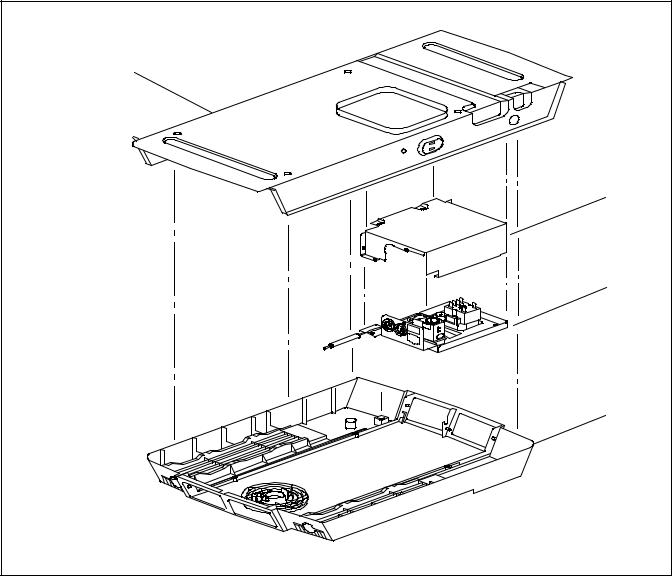
1. |
Cover Assembly |
7. |
Condenser Coil |
2. |
Scroll Assembly -- Upper |
8. |
Scroll Assembly -- Lower |
3. |
Condenser Fan |
9. |
Evaporator Coil |
4. |
Condenser Motor |
10. |
Compressor |
5. |
Evaporator Motor |
11. |
Base Pan Assembly |
6. |
Evaporator Blower Wheel |
Blow) |
See Figure 1--3 for Ceiling Package (Free-- |
|
|
|
|
|
Figure 1--4 Component Identification -- Low Profile -- Upper Unit |
||
10/09 |
1--7 |
T--298 |
|
1 |
2 |
3 |
12 |
11 |
10 |
4 |
5 |
6 |
7 |
9 |
8 |
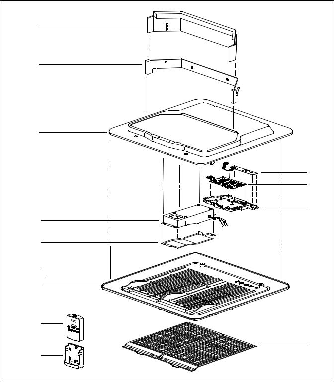
1. |
Telescoping Divider (3 different sizes available) |
7. |
Remote Control Assembly |
2. |
Divider Assembly |
8. |
Remote Control Bracket Assembly |
3. |
Frame Panel, Insulation Assembly |
9. |
Filter Assemblies (2) |
4. |
Control Box Assembly |
10. |
PCB Cover |
5. |
Control Box Cover |
11. |
PCB Main Assembly |
6. |
Suction Packing Assembly |
12. |
PCB Display |
Figure 1--5 Component Listing--Ceiling Unit For Ducted Systems
T--298 |
1--8 |
10/09 |
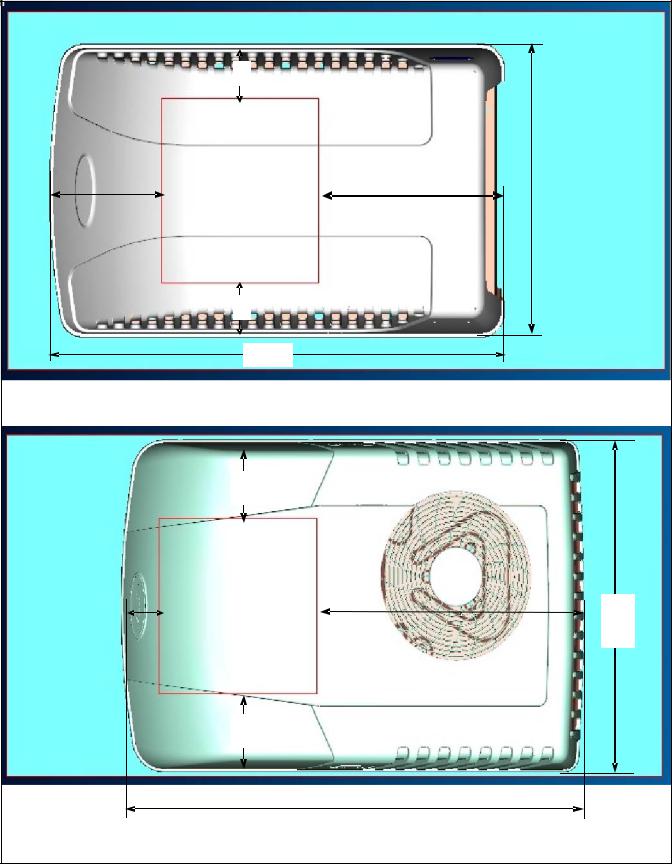
1.4 SYSTEM (UNIT) INSTALLED DIMENSIONS
Refer to Figure 1--6 thru Figure 1--9 for installation dimensions of Standard & Low Profile Upper Units & Ducted & Free--Blow Ceiling units.
4.3”
|
|
14” by 14” |
|
|
|
|
10.3” |
|
|
16.7” |
|
22.6” |
|
|
Opening |
|
|
|||
|
|
|
|
|
||
|
|
|
|
|
|
|
|
|
|
|
|
|
|
|
|
|
|
|
|
|
|
|
|
|
|
|
|
4.3” 41.0”
ROOF UNIT -- TOP VIEW -- STANDARD
6.4”
|
|
14” by 14” |
|
|
3.6” |
|
|
|
|
|
24.1” |
|||
|
|
Opening |
|
|
|
|
|
|
|
|
|
|
|
|
6.4”
|
|
41.7” |
|
|
|
|
|
|
ROOF UNIT -- TOP VIEW -- LOW PROFILE |
||
|
Figure 1--6 Unit Dimensions -- Top View -- Upper Unit (Roof) Installed |
||
10/09 |
1--9 |
|
|
26.8”
T--298
 Loading...