


CARRIER COMMERCIAL REFRIGERATION, INC.
Providing BEVERAGE-AIR • FRIGIDAIRE • KELVINATOR • UNIVERSAL NOLIN Products/Services
SERVICE & INSTALLATION MANUAL
Chest
Freezers
02/03 |
51-1371-04 |
|
|
If additional information is necessary, call the factory.
Our toll free number is 1-800-684-1199. Technical assistance engineers are willing to assist you in any way possible. Office hours are from 7:30 a.m. to 5:30 p.m., Eastern Standard Time.
Important information is contained in this manual which should be retained in a convenient location for future reference.
All data and information in this manual is subject to change without notice.
MODEL DESIGNATION INFORMATION
|
115V, 60HZ |
|
PART NO. |
|
MODELS |
52-1904-21 |
|
2SF-13 |
52-1904-22 |
|
4SF-13 |
52-1904-23 |
|
4DF-13 |
52-1904-24 |
|
6DF-13 |
52-1904-25 |
|
8DF-13 |
52-1904-33 |
|
8FR-13 |
52-1904-26 |
|
10DF-13 |
52-1904-27 |
|
14DF-13 |
52-2034-01 |
|
DI4-2 |
|
EXPORT 220V, 50HZ |
|
PART NO. |
|
MODELS |
52-1904-34 |
|
E2SF-13 |
52-1904-35 |
|
E4SF-13 |
52-1904-36 |
|
E4DF-13 |
52-1904-37 |
|
E6DF-13 |
52-1904-38 |
|
E8DF-13 |
52-1904-39 |
|
E8FR-13 |

SECTION I
General
Maintenance
& Repair
Ice Cream Cabinets
Except for routine cleaning, these chest freezers require little maintenance. In the unusual event that repair should be necessary, this manual presents information that is helpful in maintaining, diagnosing, and repairing these cabinets.
Table of Contents
GENERAL MAINTENANCE & REPAIR
Installation/Operation .......................................................... |
3 |
Grounding Instructions ...................................................... |
4 |
Cleaning Instructions .......................................................... |
5 |
Defrosting Instructions ...................................................... |
6 |
2SF / 4DF / 4SF / DI4 Specs. & Drawings .......................... |
7 |
6DF / 8DF / 10DF / 14DF Specs. & Drawings .................... |
8 |
8FR Specs. & Drawings ...................................................... |
9 |
General Operations Information ........................................ |
10 |
Cabinet Construction ........................................................ |
10 |
Cooling Tank Assembly .................................................... |
10 |
Chamber Guards .............................................................. |
10 |
Replacing Chamber Guards .............................................. |
11 |
Lids .................................................................................. |
11 |
Replacing Stainless Steel Top Cap .................................... |
11 |
Refrigerating Systems ...................................................... |
11 |
Condenser ........................................................................ |
11 |
Filter Drier ........................................................................ |
12 |
Capillary Tube .................................................................. |
12 |
Heat Exchanger ................................................................ |
12 |
Replacing Heat Exchanger ................................................ |
12 |
Refrigerant Cycle - Condenser & Evaporator .................. |
13 |
Electrical Service .............................................................. |
14 |
Thermostat ...................................................................... |
14 |
Condensate Heater ............................................................ |
15 |
Motor & Relay .................................................................. |
16 |
Checking For Electrical Trouble ........................................ |
17 |
Refrigeration Service: Compressor Installation ................ |
17 |
Refrigerant Service .......................................................... |
17 |
Cleaning System After Burnout ........................................ |
19 |
Wiring Diagram: Chest Models ........................................ |
20 |
ELECTRICAL & REFRIGERATION |
|
SPECIFICATIONS |
|
2SF-13 & 4SF-13 (R-404A) .............................................. |
21 |
4DF-13 & 6DF-13 (R-404A) .............................................. |
22 |
8DF-13 / 8FR-13 & 10DF-13 (R-404A) ............................ |
23 |
14DF-13 & DI4-1 (R-404A) .............................................. |
24 |
PARTS LISTS |
|
Cabinet Parts Illustration (R-404A) .................................. |
26 |
Cabinet Parts Listing (R-404A) ........................................ |
27 |
Cabinet Parts Listing (R-404A) Export................................ |
28 |
Condensing Unit Comp. Listing (R404A) Export ................ |
29 |
Condensing Unit Compartment Illustration (R404A) .......... |
30 |
Condensing Unit Compartment Listing (R404A) ................ |
31 |
Condensing Unit Compartment Illustration & Listing |
|
Model DI4-1........................................................................ |
32 |
8FR Parts Listing (R-404) & Accessory Mounting .......... |
33 |
Cleaning Chocolate & Syrup Pumps ................................ |
33 |
Accessory Mounting Limitations ...................................... |
34 |
Caster Assembly Installation ............................................ |
35 |
2 |
TABLE OF CONTENTS |
|
|
Installation & Operation Instructions
These instructions include information which is intended to assure the operator of correct installation, operation, and service. Before attempting installation, adjustment or maintenance, be certain of the following:
1.That you have read and fully understand the instructions.
2.That you have all the tools required and are trained to use them.
3.That you have met all installation and usage restrictions and are familiar with the functions and operation of the unit.
4.That you follow all instructions exactly as given.
All fittings, measurements, procedures and recommendations are significant. Substitutions and approximation must be avoided. Improper handling, maintenance, installation and adjustment or service attempted by anyone other than a qualified technician, may void the future warranty claims and cause damage to the unit and/or result in injury to the operator and/or bystanders.
Important information is contained in these instructions which should be retained in a convenient location for future reference.
Record for Service
Model No. __________________________________
Serial No.____________________________________
Installation Date ______________________________
Invoice Date__________________________________
Start-up Date ________________________________
Telephone for Service __________________________
INSTALLATION INSTRUCTIONS
Thermostat will maintain approximately zero degrees on the original factory setting. Turn the adjusting screw clockwise for colder and counterclockwise for warmer. IMPORTANT: Turning control counterclockwise to the stop shuts cabinet "OFF".
For storage of package ice cream, turn thermostat to coldest position. Limit top layer of package to a height consistent with cabinet usage and turn over of product.
LOCATION
Select a location for the cabinet which will be most convenient for the customer and which will allow adequate air circulation. Restricted air flow will result in higher condensing pressures and operating costs.
Provide at least a 1-inch space around the exterior of the cabinet. The outside shell is the condenser and depends on the natural convection of room air for dissipation of its heat. Stainless or formica facing sheets applied to the cabinet exterior should be in tight contact with the cabinet's outer walls to improve the heat flow.
When a cabinet is built into a counter or back-bar and space is allowed between the counter and the cabinet walls, provide holes or louvers along the top edge for hot air to escape. Holes should be screened to keep insects and rodents out.
IMPORTANT: Before building any piece of equipment in, run it to be sure the operation is satisfactory.
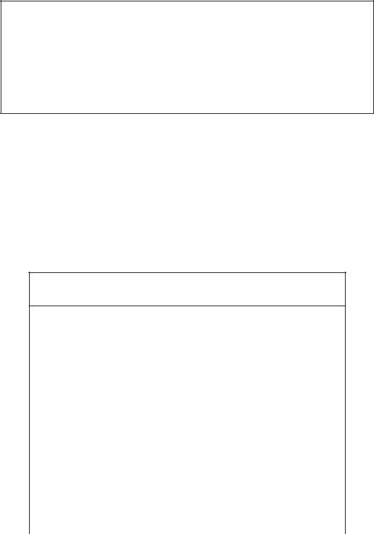
BE SAFE. SEE ILLUSTRATION ABOVE.
When a cabinet is installed in a moving vehicle, use the original crate mounting angles or equivalent to securely bolt the cabinet to the vehicle floor so it won't move going around corners or during sudden starts and stops.
INSTALLATION & OPERATION |
3 |
|
|

Grounding Instructions
This appliance is equipped with a three-prong (grounding) plug for your protection against shock hazards. The appliance should be plugged directly into a properly grounded three-prong receptacle.
Where a two-prong wall receptacle is encountered, it must be replaced with a properly grounded three-prong receptacle in accordance with the National Electrical Code and local codes and ordinances. The work must be done by a licensed electrician.
IMPORTANT
Do not, under any circumstances cut or remove the round grounding prong from the appliance plug.
WARNING
Consult a licensed electrician if you have any doubt about the grounding of your wall receptacle. Only a licensed electrician can determine the polarization of your wall receptacle. Only a properly installed threeprong wall receptacle assures the proper polarization with the appliance plug.
15 Amp
15 Amp
20 Amp |
20 Amp |
|
4 |
GROUNDING INSTRUCTIONS |
|
|
Cleaning Instructions
DIRECTIONS FOR PROPER CARE & CLEANING
1.Wipe up spilled foods promptly.
2.Use lukewarm detergent solution for cleaning the cabinet interior, exterior, and lids. Follow with a clean, damp cloth and then wipe dry.
3.Protect the exterior enamel finish and plastic lid frame with automotive type cleaner and wax.
4.Protect all stainless steel surfaces with a commercial silicone emulsion type cleaner. This cleaner is excellent for all stainless steel surfaces. It leaves a protecting film that prevents fingermarking and the adherence of food particles.
5.CAUTION:
a.Never use naptha or solvent type cleaner on plastic parts or lid frames.
b.Never use harsh abrasive polishes on plastic parts or plastic lid frames.
c.Do not blow steam or dash excessively hot water against plastic materials when cleaning the tank or defrosting, as damage to plastic parts may occur.
6.When the cabinet is taken out of service for more than a short period:
a.Remove lids. (DO NOT replace them on the cabinet until the cabinet is again refrigerated.)
b.Defrost cabinet and remove any spilled ice cream from the chamber guards.
c.Wash and dry chamber guards and cabinet interior. (See Item 2 above.)
INSTRUCTIONS FOR SEALING CABINET TO FLOOR
The National Sanitation Foundation recommends these cabinets be sealed to the floor to prevent water, dirt and vermin, etc. from getting under the cabinet. The instructions below meet their requirements.
1.Position and level the cabinet.
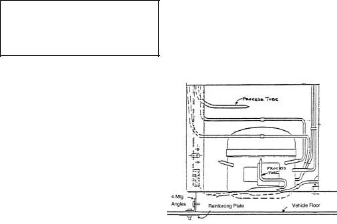
2.Draw outline of the base on the floor.
3.Raise and block the front side of the cabinet as illustrated in FIG. 1.
4.Apply a bead of mastic (See approved list below) to the floor one half inch inside the outline drawn. (See FIG. 2.) Bead must be heavy enough to compress at all points when the cabinet is set down.
5.Raise and block the rear of the cabinet as illustrated in FIG. 1.
6.Apply mastic on the floor as outlined in step 4 on the other three sides.
7.Examine to see that cabinet is sealed to floor around entire perimeter.
NOTE. Asphalt floors are very susceptible to chemical attack. A layer of tape on the floor prior to applying the mastic will protect the floor.
APPROVED MASTICS
3M |
#EC800 ............................................................ |
Caulk |
3M |
#EC2185 .......................................................... |
Caulk |
3M |
#EC1055 .......................................................... |
Bead |
3M |
#EC1202 .......................................................... |
Bead |
Armstrong Cork ........................................ |
Rubber Caulk |
|
Products Research Co. #5000.................. |
Rubber Caulk |
|
G.E. Silicone Sealer |
|
|
FIG. 1 |
FIG. 2 |
CLEANING INSTRUCTIONS |
5 |
Defrosting Instructions
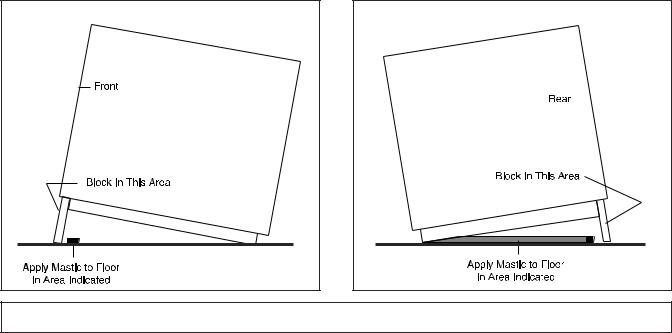
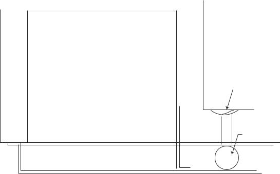
COMPRESSOR COMPARTMENT
DRAIN IN LINER
DRAIN CAP
A drain fitting is located in the bottom of the storage tank. To drain the defrost water:
1.Remove and store products in another freezer.
2.Loosen and remove any items such as ice cream, nuts, berries, paper labels, etc., which could plug the bottom drain.
3.Remove the cap from the drain hose fitting.
4.Connect a hose to the fitting and run it to a floor drain, a shallow (2" high maximum) pan, or to a “Filordrain” at the sink.
5.Disconnect the cabinet by pulling the plug or turning the thermostat off to melt down the frost.You can hasten the defrost by using the “Filordrain” or a hose to spray warm water on the cabinet walls. (Detailed instructions for using the “Filordrain” for spraying the frost and removing the accumulated water are available from your dealer.)
6.Recap hose fitting after defrosting is complete.
6 |
GROUNDING INSTRUCTIONS |
|
|
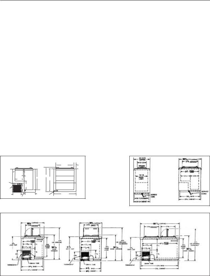
Specifications - Specifications Subject to Change without Notice.
|
DI4 |
2SF |
4DF |
4SF |
Compressor Mount |
Front |
Front |
Front |
Front |
Temperature Range |
0° to -20°F (-18° to -29°C) |
0° to -25° |
0° to -25° |
0° to -20° |
Number of Lids |
2 |
2 |
2 |
4 |
Lid Construction |
Stainless Steel, High Density, |
High Density, Foamed-in-Place |
High Density, Foamed-in-Place |
High Density, Foamed-in-Place |
|
Foamed-In-Place |
Insulation w/ Vinyl Gaskets |
Insulation w/ Vinyl Gaskets |
Insulation w/ Vinyl Gaskets |
|
Insulation w/ Vinyl Gaskets |
|
|
|
Hinge Type |
Continuous Composition |
Continuous Composition |
Continuous Composition |
Continuous Composition |
Insulation |
Polyurethane Foam |
Polyurethane Foam |
Polyurethane Foam |
Polyurethane Foam |
Wall Thickness |
2-1/4" |
2-5/16" |
2-5/16" |
2-5/16" |
Capacity |
4.9 cu. ft. |
5.4 cu. ft. |
9.1 cu. ft. |
11.3 cu. ft. |
Capacity |
|
|
|
|
3 gal. (9-1⁄2" I.D.) cans |
6 |
4 |
9 |
10 |
2-1⁄2 gal. (9" I.D.) cans |
6 |
5 |
10 |
13 |
2-1⁄2 gal.(9-1⁄4" I.D.) cans |
6 |
5 |
12 |
15 |
1⁄2 gal. packages |
— |
63 |
116 |
136 |
Shipping Weight |
210 lbs. |
212 lbs. |
247 lbs. |
294 lbs. |
Compressor Size |
1/5 HP |
1/5 HP |
1/5 HP |
1/5 HP |
Condenser Type |
Forced Convection |
No-clog, Wrap-around |
No-clog, Wrap-around |
No-clog, Wrap-around |
|
|
Radiant Shell |
Radiant Shell |
Radiant Shell |
Evaporator Type |
Cold Wall |
Cold Wall |
Cold Wall |
Cold Wall |
Refrigerant Type |
R404A |
R-404A |
R-404A |
R-404A |
Refrigerant Control |
Capillary |
Capillary |
Capillary |
Capillary |
Defrost System |
Manual |
Manual |
Manual |
Manual |
Amp Draw |
2.0 |
2.0 |
2.0 |
2.0 |
Electrical Specs. (V/Hz/Ph) |
115/60/1 |
115/60/1 |
115/60/1 |
115/60/1 |
NSF-7 (Ice Cream Storage) |
Yes |
Yes |
Yes |
Yes |
UL & CUL Listed |
Yes |
Yes |
Yes |
Yes |
Interior Finish |
Baked Enamel on Galvanized Steel |
Baked Enamel |
Baked Enamel |
Baked Enamel |
Exterior Finish |
Unpainted Galvannealed Steel |
Baked Enamel |
Baked Enamel |
Baked Enamel |
|
w/ Stainless Steel Cap |
w/ Stainless Steel Cap |
w/ Stainless Steel Cap |
w/ Stainless Steel Cap |
Electrical Information |
Conduit Connected, Max. Fuse |
15 Amp Service Cord |
15 Amp Service Cord |
15 Amp Service Cord |
|
Size: 15 Amp, Circuit Ampacity: 15A |
NEMA 5-15P Plug |
NEMA 5-15P Plug |
NEMA 5-15P Plug |
|
DI4 Front View |
|
DI4 Side View |
|
SF |
|
|
|
SQ. |
2 1/4" |
|||
|
|
Side View |
||||
|
|
|
|
22 1/4" |
||
|
|
|
|
TYP. |
||
|
|
|
|
|
|
|
|
10 7/8" |
|
|
|
|
|
|
TYP. |
|
|
|
|
|
|
|
1/2" |
29 3/8" |
|
|
|
|
11 1/8" |
25 1/2" |
|
|
|
|
|
|
27 3/4" |
|
|
||
Thermostat |
|
|
|
|
|
DF |
Handy |
|
13" |
|
|
|
|
13" |
|
|
|
|
||
Box |
|
|
|
|
Side View |
|
|
|
|
|
|
||
on Side |
|
|
|
|
|
|
|
10 1/8" |
12 1/8" |
Connector for |
21 5/8" |
|
|
|
|
|
|
|||
|
|
Drain Hose |
Reach In Opening |
|
|
|
|
|
|
|
|
||
|
Drain |
|
|
|
|
|
Model 2SF |
Model 4DF |
Model 4SF |
DI4 / 2SF / 4DF / 4SF SPECIFICATIONS |
7 |
|
|

Specifications - Specifications Subject to Change without Notice.
|
6DF |
8DF |
10DF |
14DF |
Compressor Mount |
Front |
Front |
Front |
Front |
Temperature Range |
0° to -20°F |
0° to -20° |
0° to -20° |
0° to -25° |
Number of Lids |
4 |
4 |
6 |
8 |
Lid Construction |
High Density, Foamed-In-Place |
High Density, Foamed-in-Place |
High Density, Foamed-in-Place |
High Density, Foamed-in-Place |
|
Insulation w/ Vinyl Gaskets |
Insulation w/ Vinyl Gaskets |
Insulation w/ Vinyl Gaskets |
Insulation w/ Vinyl Gaskets |
Hinge Type |
Continuous Composition |
Continuous Composition |
Continuous Composition |
Continuous Composition |
Insulation |
Polyurethane Foam |
Polyurethane Foam |
Polyurethane Foam |
Polyurethane Foam |
Wall Thickness |
2-5/16" |
2-5/16" |
2-5/16" |
2-5/16" |
Capacity |
14.1 cu. ft. |
18.6 cu. ft. |
23.6 cu. ft. |
31.5 cu. ft. |
Capacity |
|
|
|
|
3 gal. (9-1⁄2" I.D.) cans |
16 |
21 |
29 |
40 |
2-1⁄2 gal. (9" I.D.) cans |
19 |
25 |
33 |
47 |
2-1⁄2 gal.(9-1⁄4" I.D.) cans |
21 |
30 |
40 |
56 |
1⁄2 gal. packages |
173 |
234 |
298 |
103 |
Shipping Weight |
304 lbs. |
353 lbs. |
396 lbs. |
598 lbs. |
Compressor Size |
1/3 HP |
1/3 HP |
1/3 HP |
(2) 1/3 HP |
Condenser Type |
No-clog, Wrap-around |
No-clog, Wrap-around |
No-clog, Wrap-around |
No-clog, Wrap-around |
|
Radiant Shell |
Radiant Shell |
Radiant Shell |
Radiant Shell |
Evaporator Type |
Cold Wall |
Cold Wall |
Cold Wall |
Cold Wall |
Refrigerant Type |
R-404A |
R-404A |
R-404A |
R-404A |
Refrigerant Control |
Capillary |
Capillary |
Capillary |
Capillary |
Defrost System |
Manual |
Manual |
Manual |
Manual |
Amp Draw |
3.0 |
3.0 |
5.5 |
6.0 |
Electrical Specs. (V/Hz/Ph) |
115/60/1 |
115/60/1 |
115/60/1 |
115/60/1 |
NSF-7 (Ice Cream Storage) |
Yes |
Yes |
Yes |
Yes |
UL & CUL Listed |
Yes |
Yes |
Yes |
Yes |
Interior Finish |
Baked Enamel on Galvanized Steel |
Baked Enamel |
Baked Enamel |
Baked Enamel |
Exterior Finish |
Unpainted Galvannealed Steel |
Baked Enamel |
Baked Enamel |
Baked Enamel |
|
w/ Stainless Steel Cap |
w/ Stainless Steel Cap |
w/ Stainless Steel Cap |
w/ Stainless Steel Cap |
Electrical Information |
15 Amp Service Cord |
15 Amp Service Cord |
15 Amp Service Cord |
15 Amp Service Cord |
|
NEMA 5-15P Plug |
NEMA 5-15P Plug |
NEMA 5-15P Plug |
NEMA 5-15P Plug |
Model 6DF |
Model 10DF |
Model 8DF |
Model 14DF |
8 |
6DF / 8DF / 10DF / 14DF SPECIFICATIONS |
|
|
Specifications - Specifications Subject to Change without Notice.
|
8FR |
Compressor Mount |
Front |
Temperature Range |
0° to -20°F |
Number of Lids |
2 |
Lid Construction |
High Density, Foamed-In-Place |
|
Insulation w/ Vinyl Gaskets |
Hinge Type |
Continuous Composition |
Insulation |
Polyurethane Foam |
Wall Thickness |
2-5/16" |
Capacity |
14.1 cu. ft. |
Capacity |
|
3 gal. (9-1⁄2" I.D.) cans |
21 - 12 top / 9 bottom |
2-1⁄2 gal. (9" I.D.) cans |
25 |
2-1⁄2 gal.(9-1⁄4" I.D.) cans |
30 |
1⁄2 gal. packages |
234 |
Shipping Weight (Approx.) |
353 lbs. |
Compressor Size |
1/3 HP |
Condenser Type |
No-clog, Wrap-around |
|
Radiant Shell |
Evaporator Type |
Cold Wall Shell |
Refrigerant Type |
R404A |
Refrigerant Control |
Capillary |
Defrost System |
Manual |
Amp Draw |
3.0 |
Electrical Specs. (V/Hz/Ph) |
115/60/1 |
NSF-7 (Ice Cream Storage) |
Yes |
UL & CUL Listed |
Yes |
Interior Finish |
Baked Enamel on Galvanized Steel |
Exterior Finish |
Baked Enamel |
|
w/ Stainless Steel Cap |
Electrical Information |
15Amp Service Cord |
|
NEMA 5-15P Plug |
8FR
8FR SPECIFICATIONS |
9 |
|
|
Operation - General
All the chest freezer models are of the same basic design consisting of a hot wall condenser cap tube fed tank wrap evaporator. Ice formation on the walls over a period of time is normal. This frost should be scraped off periodically in order to maintain peak performance. These cabinets are thermostatically controlled for various temperature requirements. The thermostat is located post adjacent to the unit compartment and can be accessed for adjustment by the user with a screwdriver or a dime. Thermostat position #1 being the warmest and position #7 being the coldest.
These cabinets are manual defrost and a drain is provided for periodic cleaning. A garden hose can be attached to the drain plug for draining any water that may accumulate. This drain attachment is located in the front base rail of the cabinet.
NOTE: The power supply cord must be disconnected when cleaning or servicing these cabinets.
On initial cabinet pulldown, the hot wall condenser may become warm to the touch until the normal operating temperatures are achieved.
Refer top model serial data tag for cabinet amperage, refrigerant charges and type.
CABINET CONSTRUCTION
The low side tank is lowered into the outer shell and anchored to the sub top by a plastic extrusion and foam.
The space between the outer wrapper and the inner tank is then filled with urethane foam insulation (2-1⁄4"
thick) forming a three-ply wall of single unit construction. The low side tank then is not removable and no repair of the low side can be made.
The stainless steel top capping is of drawn one piece construction. It is put in place after the inner tank is assembled to the wrapper and is secured to the sides of the cabinet with 1⁄8" pop rivets.
COOLING TANK ASSEMBLY
The low side assemblies are designed so that the sides and the ends of the tank are refrigerated.
The evaporator coil assembly on the tank is different to that on previous models. It is now a serpentine coil arrangement. The new evaporator starts at the top of the inner tank and spirals downward to the condensing unit.
The thermostat bulb well is located near the front of the machine compartment in all models.
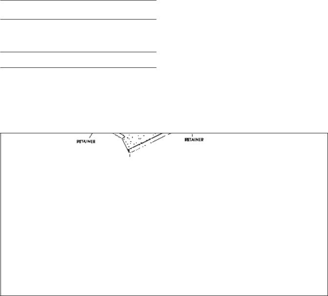
CHAMBER GUARDS
The one-piece vinyl chamber guard extends from the top of the lid opening down into the inner tank.
Galvanized steel chamber guard retainers mounted in the top of the tank frame hold the vinyl chamber guard against the top stainless steel capping. A special sealing compound laid on the inside angle of the retainers seals the vinyl to the stainless steel capping. One-piece retainer brackets along the lower edge of the tank frame retain the lower edge of the vinyl chamber guard.
To remove the vinyl chamber guard, merely unhook from lower edge of the brackets and the top edge of the chamber guard retainers. (See below)
10 |
GENERAL OPERATIONS |
|
|
 Loading...