


CARRIER COMMERCIAL REFRIGERATION, INC.
Providing BEVERAGE-AIR • FRIGIDAIRE • KELVINATOR • UNIVERSAL NOLIN Products/Services
SERVICE &
INSTALLATION
MANUAL
Frozen Food
& Ice Cream
Merchandisers
CMCT
2/03 |
51-1021-01 |
|
|

If additional information is necessary, call the factory.
Our toll free number is 1-800-684-1199. Technical assistance engineers are willing to assist you in any way possible. Office hours are from 8:00a.m. to 5:30 p.m., Eastern Standard Time.
Important information is contained in this manual which should be retained in a convenient location for future reference.
All data and information in this manual is subject to change without notice.
MODEL DESIGNATION INFORMATION
115V, 60HZ
PART # |
MODEL # |
DATA PLATE |
52-2038-01 |
CMCT4-4 |
SL12/CMCT4 |
52-2038-03 |
CMCT6-4 |
SL20/CMCT6 |
52-2038-05 |
CMCT8-4 |
SL28/CMCT8 |
52-2038-06 |
CMCT10-4 |
SL36/CMCT10 |
|
EXPORT 220V, 50HZ |
|
PART # |
MODEL # |
DATA PLATE |
52-2040-01 |
ECMCT4-4 |
ECMCT4 |
52-2040-02 |
ECMCT6-4 |
ECMCT6 |
52-2040-04 |
ECMCT8-4 |
ECMCT8 |

SECTION I
Introduction

CMCT Merchandisers – Introduction
These cabinets are produced for the merchandising of frozen food and ice cream markets. They range in size from 4' to 10' in length. Operating ambients range from 70ºF. to 85ºF. with cavity temperatures at load line between 0ºF. to -20ºF.
Except for routine cleaning, these cabinets will require little maintenance. In the unusual event that repair should be necessary, this manual presents information that is helpful in maintaining, diagnosing, and repairing these cabinets.
INTRODUCTION |
3 |
|
|
TABLE OF CONTENTS |
|
INTRODUCTION |
|
Introduction .................................................................... |
3 |
Table of Contents ............................................................ |
4 |
Specifications & Illustrations ............................................ |
5 |
Handling & Installation .................................................... |
6 |
Cleaning Instructions ........................................................ |
7 |
Cabinet Operation ............................................................ |
7 |
Electrical Data .................................................................. |
9 |
Refrigeration/Electrical Specs. (R404A)............................ |
10 |
Refrigeration/Electrical Data Export Models...................... |
11 |
Wiring Diagram CMCT Models 4, 6 & 8 .......................... |
12 |
Wiring Diagram CMCT Models 10 .................................... |
13 |
Wiring Diagram ECMCT Models 4, 6 & 8 (Export) .......... |
14 |
Lamp Wiring Detail (Upper Raceway) .............................. |
15 |
MAINTENANCE & REPAIR |
|
Cabinet Temperature Control ............................................ |
19 |
Electrical Box Layout ........................................................ |
20 |
Defrost Timer Layout ........................................................ |
21 |
Cabinet Electrical Supply .................................................. |
22 |
Condensing Unit Assembly .............................................. |
23 |
Condensing Unit Layout.................................................... |
24 |
Unit Compartment - Rear.................................................. |
25 |
Evaporator Tubing Illustration .......................................... |
26 |
New Lubricants ................................................................ |
27 |
Back Pressure Valve ........................................................ |
28 |
Light Channel Assembly .................................................. |
29 |
Baffle Heater comp. ID & Removal .................................. |
30 |
End Panel Breaker & Heater Removal .............................. |
31 |
Refrig. Upper Section Comp. ID & Removal .................... |
32 |
Upper Cross Section ........................................................ |
33 |
Front Glass Heater Replacement ...................................... |
34 |
Countertop ........................................................................ |
35 |
Evaporator Coil Removal .................................................. |
36 |
Troubleshooting Guide...................................................... |
38 |
PARTS LISTS |
|
CMCT Cabinet Exterior Parts ID ...................................... |
40 |
Parts List CMCT-4, 6, 8 & 10............................................ |
41 |
Parts List EMCT-4, 6 & 8 .................................................. |
42 |
Due to the manufacturer’s policy of continuous quality improvement, specifications are subject to change without notice.
4 |
TABLE OF CONTENTS |
|
|
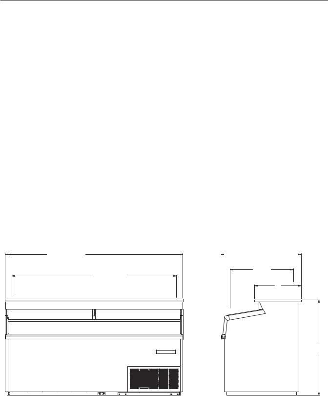
Specifications - Specifications Subject to Change without Notice.
|
CMCT-4 |
CMCT-6 |
CMCT-8 |
CMCT-10 |
Temperature Range |
0° to -20°F |
0° to -20°F |
0° to -20°F |
0° to -20°F |
Insulation |
21⁄2" Urethane Foam in Place |
21⁄2" Urethane Foam in Place |
21⁄2" Urethane Foam in Place |
21⁄2" Urethane Foam in Place |
Number of Lids |
2 |
2 |
3 |
4 |
Lid Construction |
3/16" Glass Radiant Heated |
3/16" Glass Radiant Heated |
3/16" Glass Radiant Heated |
3/16" Glass Radiant Heated |
Capacity |
11 cu. ft. |
19 cu. ft. |
27 cu. ft. |
35 cu. ft. |
Capacity (1/2 gallons) |
120 |
225 |
322 |
435 |
Novelty Baskets Load Level |
10 |
14 |
20 |
26 |
Capacity Novelty Baskets Total |
16 |
24 |
36 |
48 |
Shipping Weight (Approx.) |
486 lbs. |
624 lbs. |
780 lbs. |
874 lbs. |
Compressor Size |
1/2 HP |
1/2 HP |
3/4 HP |
1 HP |
Condenser Type |
Bare Tube Forced Air |
Bare Tube Forced Air |
Bare Tube Forced Air |
Fin & Tube Forced Air |
Evaporator Type |
Fin & Tube Gravity Coil & Cold Wall |
Fin & Tube Gravity Coil & Cold Wall |
Fin & Tube Gravity Coil & Cold Wall |
Fin & Tube Gravity Coil & Cold Wall |
Refrigerant Type |
R404A |
R-404A |
R-404A |
R-404A |
Refrigerant Control |
Capillary |
Capillary |
Capillary |
Capillary |
Defrost System |
Electric |
Electric |
Electric |
Electric |
Rated Amps |
8.0 |
8.0 |
12 |
4.8 (11V0/6.7 (230V) |
Electrical Specs. (V/Hz/Ph) |
115/60/1 |
115/60/1 |
115/60/1 |
115 & 230/60/1 |
Power Cord |
15 Amp Cord |
15 Amp Cord |
15 Amp Cord |
Conduit Connected / Max. Fuse |
|
with 5-15P NEMA Plug |
with 5-15P NEMA Plug |
with 5-15P NEMA Plug |
Size 15A Min. Circuit Ampacity 15A |
NSF-7 (Ice Cream Storage) |
Yes |
Yes |
Yes |
Yes |
UL & CUL Listed |
Yes |
Yes |
Yes |
Yes |
Interior Finish |
White Baked Enamel |
White Baked Enamel |
White Baked Enamel |
White Baked Enamel |
Exterior Finish |
White Baked Enamel |
White Baked Enamel |
White Baked Enamel |
White Baked Enamel |
Lighted Sign |
Standard |
Standard |
Standard |
Standard |
481/16 (CMCT4) |
|
|
|
|
|
721/16 (CMCT6) |
|
|
329/16 |
|
|
961/16 (CMCT8) |
|
|
|
||
|
|
|
|
||
1201/16 (CMCT10) |
253/4 |
|
|||
423/4 (CMCT4) |
|
||||
663/4 (CMCT6) |
|
|
INSIDE |
||
783/4 (CMCT8) |
|
|
|
|
|
1143/4 (CMCT10) |
19 |
||||
INSIDE |
|||||
|
|
|
|
||
|
|
|
|
|
|
383/4
INTRODUCTION |
5 |
|
|

SECTION I – HANDLING & INSTALLATION
FREIGHT DAMAGES AND SHORTAGES
IMPORTANT: The cabinet was inspected and packaged at the factory, and should
arrive in excellent condition. The transportation company or other parties involved in the shipment are responsible for loss and/or damage. Always make an inspection before and after uncrating. Inspect the crated unit(s) before locating (preferably at the point of unloading by the transportation company).
INSPECTING FOR DAMAGES
Always use care when removing shipping NOTE: tape, blocks, pads, hardware or other material until you are satisfied that the unit is completely operational.
Check the cartons or containers. If these are damaged in any way, open them and inspect the contents in the driver’s presence. If damage is detected:
1.Have the driver note the nature and extent of the damage on the freight bill.
2.Notify the transportation company’s office to request an inspection. Carrier claim policies usually require inspections to be made within 15 days of delivery.
3.If damage is noticed, file a claim with the transportation company.
FILING A CLAIM
File a claim for loss at once with the transportation company for:
A. A cash adjustment; B. Repairs; or C. Replacement
When filing your claim, retain all packaging materials and receipts.
HANDLING THE CABINET
NOTE: The refrigeration system of the cabinet is designed to operate with the cabinet located on a level surface. Do not tilt the cabinet more than
10° to any side. If the cabinet must be tilted on an angle for handling or moving purposes, allow it to sit in an upright position 30 minutes prior to starting.
The cabinet must be installed on a sturdy, solid, level floor.
The cabinet must be located so it can be plugged or wired into a properly grounded three-prong electrical outlet of 115/220 volt, 60 hz. The electrical outlet should not be controlled by a wall switch which might be turned off accidentally.
UNCRATING THE CABINET
The cabinet should be moved as close as possible to the operating location before removing crate base. Be sure to follow the steps in the “INSPECTING FOR DAMAGES” instructions.
INSTALLING THE CABINET
After removing the skid from the cabinet, slide cabinet into location. Level cabinet to insure proper draining of the defrost water.
To meet NSF requirements, these cabinets must be sealed to the floor with an NSF or FDA approved sealant.
Remove the front grill from cabinet. Remove front hold down bolts and pull unit out of cabinet. Remove shipping band from compressor. Be sure that the compressor “floats” freely on the compressor springs. Check refrigeration lines to see that they are “free” and no damage was done in shipping. Check fan blade for free operation.
Check voltage and amp draw on the serial plate to determine proper fuse and line size. Voltage should be checked at the compressor terminals as the compressor is starting, to determine if there is excessive “voltage drop.” This voltage drop should not exceed 10% of the rated compressor voltage. If the voltage reads 115 or 230 with no load and it drops below 103 or 208 when the compressor tries to start, it is an indication that the supply wiring is too small in size or too long in length.
It is recommended that a separate circuit be run for each cabinet to prevent the possibility of another appliance blowing a fuse causing subsequent loss of product.
CHOOSING A LOCATION
This model cabinet should be situated to allow proper air circulation. Cabinets require a 2" minimum clearance behind for proper air circulation.
6 |
INTRODUCTION |
|
|
CLEANING INSTRUCTIONS
CLEANING THE CABINET EXTERIOR
Wipe the exterior occasionally with a cloth dampened in mild detergent water; rinse, and wipe dry with a soft, dry cloth. Do not use abrasive or caustic cleaners or scouring pads.
CLEANING THE CONDENSER
Periodic cleaning of the condenser can be easily accomplished by brushing the coils with a soft brush and/or using a vacuum cleaner with a brush attachment.
Be sure that dirt, dust, and a collection of other debris do not build up to a point that air circulation through the condenser is restricted.
CLEANING THE STORAGE COMPARTMENT
1.Remove product and store it in another suitable cabinet, if possible. Be sure to prevent spoilage of the product which may occur if it is left at room temperature.
2.Turn OFF the thermostat and unplug the cabinet.
3.Defrost completely prior to cleaning.
4.Wash the entire interior storage area with warm water and baking soda solution — about a tablespoon of baking soda per quart of water. Rinse thoroughly with clean water and wipe dry.
5.A drain hose is provided. Connections are made to fit a standard garden hose for ease of draining water from inside of the tank area.
IMPORTANT:
Do not use any objects or cleaners which may leave residues, odors, or particles. Avoid the use of strong chemicals or abrasive cleaners which may damage the interior surfaces and contaminate product within the storage area.
6.Be sure to correctly plug in to cabinet, set the temperature control, and allow time for cooling of the storage area before storing product.
DESCRIPTION OF REFRIGERATION
SYSTEM: CONDENSING UNIT
All CMCT cabinets are equipped with Copelametic compressors utilizing 404A refrigerant:
1/2 HP on the CMCT-4 and CMCT-6
3/4 HP on the CMCT-8
1 HP on the CMCT-10
A back pressure valve is used to protect the compressor against excessive pressures during initial cabinet start-up and upon termination of the defrost cycle. This valve is factory pre-set to limit the crankcase pressure to 10# and should not be changed.
CABINET OPERATION
REFRIGERATION CYCLE:
Refrigeration is accomplished by both a “wrap-around” tank coil and fin coil. This tank coil consists of several passes of copper tubing wrapped completely around the tank or product compartment. The fin coil located behind the light fixture serves two purposes — it creates a blanket of cold air over the product and collects moisture in the form of frost from the warm air entering the cabinet, thus reducing frost collection on the tank coil. The refrigerant enters the top of the tank coil first and progresses downward to the bottom of the tank; from there it enters the top of the fin coil and again downward. By circuiting the refrigeration in this manner, it assures the fin coil of being the coldest part of the system.
DEFROST CYCLE:
Because of the large size and fin arrangement, the CMCT fin coils have the ability to collect a large amount of frost before becoming blocked. These features permit the CMCT cabinets to operate on one defrost cycle per 24 hours, thus reducing product shock to the ice cream.
The fin coil and drain pan are defrosted with one 4- pass heater located on the underside of the evaporator assembly. The back pass of the heater lays in the drain trough which slopes from left to right along the back edge of the drain pan.
WARNING:
To avoid the possibility of an electrical shock, turn OFF thermostat and unplug the electrical cord of the cabinet before cleaning or touching electrical connections or parts.
INTRODUCTION |
7 |
|
|
Defrosting is initiated by the time clock and terminated by a temperature thermostat set to close at 76°F. When this thermostat closes, it energizes a solenoid in the time clock which in turn trips the clock mechanism off defrost. Should this thermostat fail to close, the defrost cycle will be terminated by the failsafe pin on the time clock (set at 40 minutes).
As an additional safety feature, the temperature limiting thermostat is wired in series with the defrost heater. This thermostat will also open the heater circuit when the top coil reaches 76°F. should any malfunction of the defrost thermostat occur.
Any time the system has been opened and NOTE: exposed to the atmosphere, a new drier should be installed, system completely evacuated, and recharged to the specified refrigerant and amount listed on the serial plate located inside the unit compartment on the left wall.
DO NOT ATTEMPT CHARGING BY IMPORTANT: PRESSURES ALONE!! Charge is
very critical! Charging should be accomplished by means of weighing, or the use of a charging cylinder.
8 |
INTRODUCTION |
|
|
CMCT ELECTRICAL DATA
CMCT-4 |
OHMS |
WATTS |
AMPS |
VOLTS |
|
|
|
|
|
|
|
Def. Heater on Bottom side |
24.7 |
582 |
4.8 |
120 |
|
of Top Coil |
|||||
|
|
|
|
||
|
|
|
|
|
|
Control Bellows Heater below |
1600 |
9 |
.075 |
120 |
|
Def. Controls |
|||||
|
|
|
|
||
|
|
|
|
|
|
End Breaker Heater behind |
960 |
15 |
.12 |
120 |
|
each End Breaker |
|||||
|
|
|
|
||
|
|
|
|
|
|
Glass Heater around |
262 |
56 |
.46 |
120 |
|
Front Glass |
|||||
|
|
|
|
||
|
|
|
|
|
|
|
|
||||
CMCT-6 |
OHMS |
WATTS |
AMPS |
VOLTS |
|
|
|
|
|
|
|
Def. Heater on Bottom side |
15.9 |
904 |
7.5 |
120 |
|
of Top Coil |
|||||
|
|
|
|
||
|
|
|
|
|
|
Control Bellows Heater below |
1600 |
9 |
.075 |
120 |
|
Def. Controls |
|||||
|
|
|
|
||
|
|
|
|
|
|
End Breaker Heater behind |
960 |
15 |
.12 |
120 |
|
each End Breaker |
|||||
|
|
|
|
||
|
|
|
|
|
|
Glass Heater around |
175 |
82 |
.68 |
120 |
|
Front Glass |
|||||
|
|
|
|
||
|
|
|
|
|
|
CMCT-8 |
OHMS |
WATTS |
AMPS |
VOLTS |
|
|
|
|
|
|
|
Def. Heater on Bottom side |
11.8 |
1200 |
10 |
120 |
|
of Top Coil |
|||||
|
|
|
|
||
|
|
|
|
|
|
Control Bellows Heater below |
1600 |
9 |
.075 |
120 |
|
Def. Controls |
|||||
|
|
|
|
||
|
|
|
|
|
|
End Breaker Heater behind |
960 |
15 |
.12 |
120 |
|
each End Breaker |
|||||
|
|
|
|
||
|
|
|
|
|
|
Glass Heater around |
134 |
107 |
.89 |
120 |
|
Front Glass |
|||||
|
|
|
|
||
|
|
|
|
|
|
|
|
||||
CMCT-10 |
OHMS |
WATTS |
AMPS |
VOLTS |
|
|
|
|
|
|
|
Def. Heater on Bottom side |
3.38 |
1561 |
6.7 |
230 |
|
of Top Coil |
|||||
|
|
|
|
||
|
|
|
|
|
|
Control Bellows Heater below |
1600 |
9 |
.075 |
120 |
|
Def. Controls |
|||||
|
|
|
|
||
|
|
|
|
|
|
End Breaker Heater behind |
960 |
15 |
.12 |
120 |
|
each End Breaker |
|||||
|
|
|
|
||
|
|
|
|
|
|
Glass Heater around |
190 |
132 |
1.1 |
120 |
|
Front Glass |
|||||
|
|
|
|
||
|
|
|
|
|
|
INTRODUCTION |
9 |
|
|
REFRIGERATION/ELECTRICAL SPECIFICATIONS CMCT (404A)
CABINET |
|
|
|
|
START |
RUN |
MODEL |
MFG. |
MODEL |
HP |
VOLTS |
AMPS |
AMPS |
CMCT-4 |
Copeland |
KAGB-005E-IAA-222 |
1/2 |
115 |
45 |
8.0 |
|
|
|
|
|
|
|
CMCT-6 |
Copeland |
KAGB-005E-IAA-222 |
1/2 |
115 |
45 |
8.0 |
|
|
|
|
|
|
|
CMCT-8 |
Copeland |
KAJB-007E-IAA-222 |
3/4 |
115 |
59 |
12.0 |
|
|
|
|
|
|
|
CMCT-10 |
Copeland |
KALB-010E-CAV-221 |
1 |
230/208 |
33.5 |
8.1 |
|
|
|
|
|
|
|
REFRIGERATION CYCLE (80° Ambient)
CABINET |
REFRIG. |
DEFROST |
|
|
CAP. |
|
|
CONTROL |
CAVITY |
|
MODEL |
CYCLE |
CYCLE |
REFRIG. |
OZ. |
TUBE |
SUCT. |
DISCH. |
SETTING |
TEMP. |
|
CMCT-4 |
8.0 - 115V |
6.8 - 115V |
404A |
22 |
8' x .042 ID |
2# |
225# |
No. 7 |
-22°F |
|
|
|
|
|
|
|
|
|
|
|
|
CMCT-6 |
8.0 - 115V |
8.4 - 115V |
404A |
23 |
8' x .042 ID |
5# |
223# |
No. 7 |
-19°F |
|
|
|
|
|
|
|
|
|
|
|
|
CMCT-8 |
12.0 - 115V |
12.0 - 115V |
404A |
27 |
7' x .049 ID |
2# |
228# |
No. 7 |
-22°F |
|
|
|
|
|
|
|
|
|
|
|
|
CMCT-10 |
8.1 - 230V |
6.7 - 230V |
404A |
29 |
7' x .054 ID |
2# |
223# |
No. 7 |
-27°F |
|
4.8 - 115V |
4.8 - 115V |
|||||||||
|
|
|
|
|
|
|
|
NOTE: Refer to Data plate for refrigerant type and charge.
Condenser Fan ............ |
G.E. 5KSM51GG37845 or |
Temperature Control |
........ RANCO A10-4491-00 |
|
|
5KPM51BL-40466 (Reversible Motor) |
Back Pressure Valve |
|
|
|
230 - V.E.M.S. ESP-L35-EM2 |
............Sporlan 10# setting |
||
Time Clock |
|
|
|
CRO-4-0-20 |
..............115 |
Paragon 145-00B (24 Hr.) |
|
CRO-6-0-60 (CMCT-10) |
|
|
230V |
Paragon 145-20B (24 Hr.) |
|
|
10 |
INTRODUCTION |
|
|
ECMCT REFRIGERATION/ELECTRICAL DATA
Export Models (R-404A)
ECMCT-4 |
OHMS |
WATTS |
AMPS |
VOLTS |
|
|
|
|
|
|
|
Def. Heater on Bottom side |
72.4 |
582 |
2.7 |
215 |
|
of Top Coil |
|||||
|
|
|
|
||
|
|
|
|
|
|
Control Bellows Heater below |
5375 |
9 |
.04 |
215 |
|
Def. Controls |
|||||
|
|
|
|
||
|
|
|
|
|
|
End Breaker Heater behind |
3071.4 |
15 |
.07 |
215 |
|
each End Breaker |
|||||
|
|
|
|
||
|
|
|
|
|
|
Glass Heater around |
826.9 |
56 |
.26 |
215 |
|
Front Glass |
|||||
|
|
|
|
||
|
|
|
|
|
|
Heated Glass Lid |
41.3 |
14 |
.58 |
24 |
|
(each) |
|||||
|
|
|
|
||
|
|
|
|
|
ECMCT-6 |
OHMS |
WATTS |
AMPS |
VOLTS |
|
|
|
|
|
|
|
Def. Heater on Bottom side |
51 |
904 |
4.2 |
215 |
|
of Top Coil |
|||||
|
|
|
|
||
|
|
|
|
|
|
Control Bellows Heater below |
5375 |
9 |
.04 |
215 |
|
Def. Controls |
|||||
|
|
|
|
||
|
|
|
|
|
|
End Breaker Heater behind |
3071.4 |
15 |
.07 |
215 |
|
each End Breaker |
|||||
|
|
|
|
||
|
|
|
|
|
|
Glass Heater around |
565.8 |
82 |
.38 |
215 |
|
Front Glass |
|||||
|
|
|
|
||
|
|
|
|
|
|
Heated Glass Lid |
26.1 |
22 |
.92 |
24 |
|
(each) |
|||||
|
|
|
|
||
|
|
|
|
|
COMPRESSOR AMPERAGE
CABINET |
|
|
|
|
|
RUN |
|
CAP. |
MODEL |
MFG. |
MODEL |
HP |
VOLTS |
LRA |
AMPS |
OZ. |
TUBE |
ECMCT-4 |
Copeland |
KAJB-010E-CAV |
1 |
200 |
40 |
8.0 |
20 |
8' x .042 |
|
|
|
|
|
|
|
|
|
ECMCT-6 |
Copeland |
KAJB-010E-CAV |
1 |
200 |
40 |
8.0 |
25 |
8' x .042 |
|
|
|
|
|
|
|
|
|
INTRODUCTION |
11 |
|
|
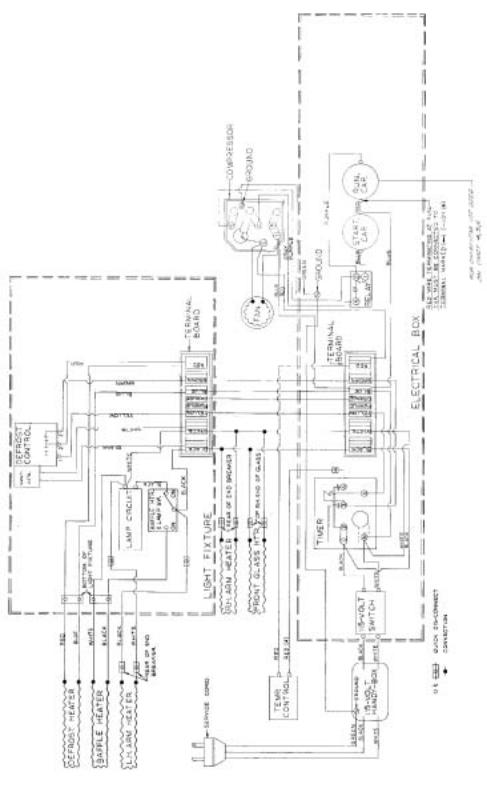
WIRING DIAGRAM – 00-1667-00
CMCT-4, 6, & 8
12 |
INTRODUCTION |
|
|
 Loading...