


CRECOMZR076A00 |
Small Rooftop Products |
CRECOMZR078A00 |
Select 3 to 12 1/2 Tons |
CRECOMZR080A00 |
Vertical EconoMi$er X Accessory |
|
Installation Instructions |
Read these instructions completely before attempting to install the Vertical EconoMi$er X Accessory.
CONTENTS
SAFETY CONSIDERATIONS . . . . . . . . . . . . . .1 GENERAL. . . . . . . . . . . . . . . . . . . . . . . . . . . . . .1 EconoMi$er X Sensor Usage . . . . . . . . . . . . . 2 ACCESSORIES LIST. . . . . . . . . . . . . . . . . . . . .2 WIRING DIAGRAMS. . . . . . . . . . . . . . . . . . .5-7 INSTALLATION . . . . . . . . . . . . . . . . . . . . . . . .2-8 EconoMi$er X Standard Sensors . . . . . . . . . .8 EconoMi$er X Control Modes . . . . . . . . . .8-14 OPERATION . . . . . . . . . . . . . . . . . . . . . . . . . . .16 TROUBLESHOOTING . . . . . . . . . . . . . . . . . . .17
SAFETY CONSIDERATIONS
Improper installation, adjustment, alteration, service, maintenance, or use can cause explosion, fire, electrical shock or other conditions which may cause personal injury or property damage. Consult a qualified installer, service agency, or your distributor or branch for information or assistance. The qualified installer or agency must use factoryauthorized kits or accessories when modifying this product. Refer to the individual instructions packaged with the kits or accessories when installing.
Follow all safety codes. Wear safety glasses and work gloves. Use quenching cloths for brazing operations and have a fire extinguisher available. Read these instructions thoroughly and follow all warnings or cautions attached to the unit. Consult local building codes and appropriate national electrical codes (in USE, ANSI/NFPA70, National Electrical Code (NEC); in Canada, CSA C22.1) for special requirements.
It is important to recognize safety information. This is the safety-alert symbol ! . When you see this symbol on the unit and in instructions or manuals, be alert to the potential for personal injury.
Understand the signal words DANGER, WARNING, CAUTION, and NOTE. These words are used with the safety-alert symbol. DANGER identifies the most serious hazards which will result in severe personal injury or death. WARNING signifies hazards which could result in personal injury or death. CAUTION is used to identify unsafe practices, which may result in minor personal injury or product and property damage.
NOTE is used to highlight suggestions which will result in enhanced installation, reliability, or operation.
! WARNING
ELECTRICAL SHOCK HAZARD
Failure to follow this warning could cause personal injury or death. Before performing service or maintenance operations on the unit, always turn off main power switch to unit and install lock(s) and lockout tag(s). Unit may have more than one power switch. Ensure electrical service to rooftop unit agrees with voltage an amperage listed on the unit rating plate.
! CAUTION
CUT HAZARD
Failure to follow this caution may result in personal injury.
Sheet metal parts may have sharp edges or burrs. Use care and wear appropriate protective clothing, safety glasses and gloves when handling parts and servicing roof top units.
GENERAL
IMPORTANT: These economizers meet the economizer requirements as laid out in California’s Title 24 mandatory section 120.2 (fault detection and diagnostics).
The EconoMi$er X system utilizes the latest technology available for integrating the use of free cooling with mechanical cooling for packagedrooftopunits.Thesolid-statecontrolsystemoptimizesenergy consumption, zone comfort, and equipment cycling by operating the compressors when the outdoor-air temperature is too warm, integrating the compressor with outdoor air when free cooling is available, and locking out the compressor when outdoor-air temperature is too cold. Demand control ventilation is supported.
This EconoMi$er X can be used with 1, 2, or 3 speed (48/50LC 07-12) units.
The EconoMi$er X system utilizes gear-drive technology with a directmount spring return actuator that will close upon loss of power. The EconoMi$er X system comes standard with an outdoor air temperature sensor, mixed air temperature sensor. Outdoor enthalpy, indoor enthalpy, indoor temperature, and CO2 sensors are available for field installation. See Table 3 for sensor usage.
Standard barometric relief dampers provide natural building pressurization control. An optional power exhaust system is available for applications requiring even greater exhaust capabilities. The power exhaust set point is adjustable at the EconoMi$er X controller.
See Table 1 for package usage. See Table 2 for package contents. See Table 3 for sensor usage.
Table 1 - Package Usage
UNIT SIZE |
PART NUMBER |
Small Cabinet, Footprint size: 46 3/4” x 74 3/8” |
CRECOMZR076A00 |
Large Cabinet, Footprint size: 58 1/2” x 88 1/8” |
CRECOMZR078A00 |
Extra-Large Cabinet, Footprint size: 63 3/8” x 115 7/8” |
CRECOMZR080A00 |
Table 2 - Package Contents
PACKAGE NO. |
QTY |
CONTENTS |
|
1 |
Hood Top and Sides |
|
1 |
Hood Divider |
CRECOMZR076A00, |
1 |
Aluminum Filter |
18 |
Screws |
|
CRECOMZR078A00 |
1 |
EconoMi$er X Assembly |
|
1 |
HH79ZZ007 Mixed (supply) |
|
1 |
Temperature Sensor |
|
48TMHSRSE--A20 Harness |
|
|
1 |
Hood Top and Sides |
|
1 |
Hood Divider |
|
1 |
Hood Filter Divider |
CRECOMZR080A00 |
2 |
Aluminum Filters |
1 |
Hardware Bag |
|
|
1 |
EconoMi$er X Assembly |
|
1 |
HH79ZZ007 Mixed (supply) |
|
1 |
Temperature Sensor |
|
48TMHSRSE--A20 Harness |
1
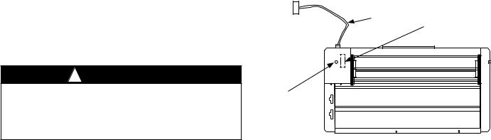
Table 3 - EconoMi$er X Sensor Usage
|
ECONOMI$ER X WITH OUTDOOR AIR |
||||||
APPLICATION |
|
DRY BULB SENSOR |
|||||
|
|
Accessories Required |
|||||
Outdoor Air |
HH79ZZ007 is factory installed on economizer |
||||||
Dry Bulb |
|||||||
|
|
|
|
|
|
||
Mixed Air |
HH79ZZ007 provided with economizer and field installed |
||||||
Sensor |
|
in blower compartment |
|||||
Single |
|
|
|
HH57AC081 |
|||
Enthalpy |
|
|
|
||||
|
|
|
|
|
|
||
Differential |
|
|
|
HH57AC081 |
|||
Enthalpy |
|
|
|
||||
|
|
|
|
|
|
||
CO2 for |
|
|
33ZCSENCO2 |
||||
DCV Control |
|
|
|||||
Using a |
|
|
|
|
or |
||
Wall-Mounted |
|
CGCDXSEN004A00 |
|||||
CO2 Sensor |
|
|
|
|
|
|
|
CO2 for |
33ZCSENCO2 or |
|
|
|
|
||
DCV Control |
CGCDXSEN004A00† |
|
OR |
|
|
||
Using a |
and |
|
|
|
CRCBDIOX005A00†† |
||
Duct-Mounted |
33ZCASPCO2 or |
|
|
|
|
||
CO2 Sensor |
CGCDXASP00100** |
|
|
|
|
||
†33ZCSENCO2 and CGCDXSEN004A00 are accessory CO2 sensors.
**33ZCASPCO2 and CGCDXASP00100 are accessory aspirator boxes required for ductmounted applications.
††CRCBDIOX005A00 is an accessory that contains both 33ZCSENCO2 and 33ZCASPCO2 accessories.
ACCESSORIES LIST
The EconoMi$er X has several field-installed accessories available to optimize performance. Refer to Table 4 for authorized parts and power exhaust descriptions
Table 4 - EconoMi$er X Field-Installed
Accessories
DESCRIPTION |
PART NUMBER |
Small Cabinet Power Exhaust 208-230 v 1 Ph |
CRPWREXH030A01 |
Small Cabinet Power Exhaust 460 v 3Ph |
CRPWREXH021A01 |
Large Cabinet Power Exhaust 208-230 v 1 Ph |
CRPWREXH022A01 |
Large Cabinet Power Exhaust 460 v 3 Ph |
CRPWREXH023A01 |
Extra Large Cabinet Power Exhaust 208-230 v 1 Ph |
CRPWREXH080A00 |
Extra Large Cabinet Power Exhaust 460 v 3 Ph |
CRPWREXH081A00 |
Outdoor Air Enthalpy Sensor |
HH57AC081 |
Indoor Air Enthalpy Sensor |
HH57AC081 |
Return Air CO2 Sensor (4 to 20 mA) |
CRCBDIOX005A00 |
CO2 Room Sensor (4 to 20 mA) |
33ZCSENCO2 or |
CGCDXSEN004A00 |
|
Aspirator Box for Duct Mount |
33ZCASPCO2 or |
CO2 Sensor (4 to 20 mA) |
CGCDXASP001A00 |
Space Temperature and CO2 Room Sensor |
33ZCT55CO2 |
with Override (4 to 20 mA) |
|
Space Temperature and CO2 Room Sensor |
33ZCT56CO2 |
with Override and Set Point (4 to 20 mA) |
|
INSTALLATION
1.Turn off unit power supply(s) and install lockout tag.
2.Remove the existing unit filter access panel. Raise the panel and swing the bottom outward. The panel is now disengaged from the track and can be removed. (See Fig. 2.)
3.Remove the indoor coil access panel and discard. (See Fig. 2.)
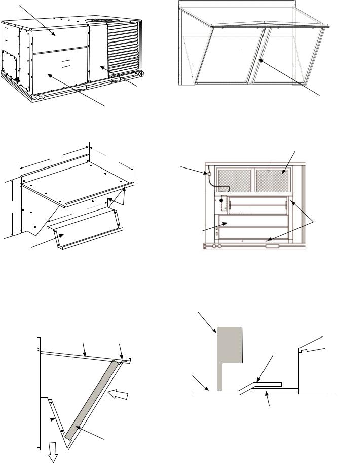
4.The EconoMi$er X hood components are shipped with the EconoMi$er X. Remove hood from packaging. The hood top and sides are shipped factory assembled.
NOTE: If the power exhaust accessory is to be installed on the unit, the hood shipped with the EconoMi$er X will not be used and may be discarded. Save the aluminum filter for use in the power exhaust hood assembly.
5.Insert the hood divider between the hood sides. (See Fig. 3) Secure hood divider with 2 screws (provided) on each hood side. Screws should go through the hood sides into the divider. The hood divider is also used as the bottom filter rack for the aluminum filter. On hood for extra large cabinet install filter divider. (See Fig. 4A.)
6.Set the EconoMi$er X upright. (See Fig. 5.)
7.Slide the EconoMi$er X assembly into the rooftop unit. (See Fig. 5). On small and large cabinets be sure to engage the rear EconoMi$er X flange under the tabs in the return-air opening of the unit base. (See Fig. 6)
8.Secure the EconoMi$er X to unit along side and bottom flanges using the screws provided.
9.Remove the tape securing the relief dampers in place.
10.Remove and save the 12-pin jumper plug from the unit wiring harness (located in the upper left corner of the unit). Insert the EconoMi$er X plug into the unit wiring harness. Refer to Fig. 7 and 8 for wiring details.
NOTE: The 12-pin jumper plug should be saved for future use, in the event that the EconoMi$er X is removed from the unit. The jumper plug is not needed as long as the EconoMi$er X is installed.
11.If EconoMi$er X will be operating under enthalpy control, replace the factory installed HH79ZZ007 outdoor dry bulb temperature sensor with accessory enthalpy sensor HH57AC081. (See Fig. 1.)
12.Remove the indoor fan motor access panel. (See Fig. 9.)
13.The mixed (or supply) air temperature sensor looks like an eyelet terminal with wires running to it. The sensor is located on the “crimp end” and is sealed from moisture. Locate the sensor in the economizer hardware bag. Mount the supply air temperature sensor (provided) to the lower left section of the indoor fan blower housing. (See Fig. 10.) Use the screw provided and use existing hole. Locate the orange and brown wires in wire bundle in the indoor fan section. Connect the orange and brown wires to the corresponding connections on the supply air temperature sensor.
(See Fig. 8.)
Wiring |
HH57AC081 |
Enthalpy Accessory |
|
Harness |
Location (Field |
|
Installed) |
Actuator
(Hidden) 
! WARNING
ELECTRICAL SHOCK HAZARD
Failure to follow this warning could result in personal injury and/ or death.
Disconnect power supply and install lockout tag before attempting to install accessory.
HH79ZZ007
Outside Air
Temperature
Sensor
Fig. 1 - EconoMi$er X Component Locations —
(Small Cabinet Economizer Shown)
2
Filter Access Panel
|
|
Compressor |
|
|
|
|
Access Panel |
|
Hood Filter |
|
|
|
|
|
|
|
Outdoor-Air Opening and |
|
Divider |
|
|
Fig. 4A - Hood for Extra Large Cabinet |
||
|
|
Indoor Coil Access Panel |
||
|
Fig. 2 - Typical Outdoor-Air Section |
|
|
|
|
Access Panel Locations |
|
|
|
|
|
|
|
HVAC Unit Filters |
|
A |
B |
|
|
|
|
Wiring |
|
|
|
|
Harness |
|
|
C |
|
Hood Top and |
|
|
D |
Side Assembly |
|
Insert |
|
|
|
|
||
|
|
|
|
Screw in |
|
|
EconoMi$er X |
EconoMi$er X |
|
|
|
Flanges |
||
Hood Divider
Fig. 3 - Hood Assembly |
Fig. 5 - EconoMi$er X Installed in HVAC Unit |
|
|
|
(Small Cabinet Economizer Shown) |
ECONOMIZER P/N |
A |
B |
C |
D |
SHIP WT. |
CRECOMZR076A00 |
33.37” |
17.43” |
19.05” |
29.5” |
55 lb |
CRECOMZR078A00 |
40.37” |
22.28” |
24.48” |
36.27” |
80lb |
CRECOMZR080A00 |
52.92” |
27.03” |
33.41” |
49.92” |
98lb |
NOTE: The CRECOMZR080A00 hood has 2 aluminum filters and a hood filter divider that installs between the filters. (See Fig. 5A.)
Hood Top |
Filter Clip |
|
Outside Air
Hood 
Divider Cleanable
Aluminum Filter
Barometric
Airflow
Fig. 4 - Filter Installation
Unit Filter
Rack
EconoMi$er X
Hold Down Tab
EconoMi$er X
Unit Base
EconoMi$er IV Rear Flange
Fig. 6 - Rear EconoMi$er X Flange Installation
(Small and Large Cabinet)
3
14.While everything is open install and wire any other accessories and/or sensors as applicable and convenient, per their installation instructions and/or the Configuration section of this instruction. Some accessories require that unit ducting already be installed.
NOTE: If also installing a power exhaust accessory, skip step 16 and follow the power exhaust instructions instead.
16.Install the EconoMi$er X hood over the EconoMi$er X. Use screws provided.
17.The W7220 EconoMi$er X controller is shipped mounted to a bracket. Install the controller / bracket in the top left corner of the unit control box as shown in wiring diagram, Fig. 8. Screw in place through pre-punched holes.
18.For 1 and 2 speed units connect the plugs coming from the
controller as shown in wiring diagram, Fig. 7 and 8A.
NOTE: Provided 48TMHSRSE--A20 harness will be connected as shown below.
19.For 3 speed (48/50LC 07-12) units, the harness attached to the
W7220 econoMi$er X controller must be removed, and can be discarded. Locate harness 48LCHSRADH--A00 shipped in plastic bag in the control box of unit. Attach this harness to the
W7220 controller as shown in Fig 8B and 8C.
NOTE: Harness 48TMHSRSE--A20 provided with economizer is not used with 3 speed (48/50LC 07-12) units.
20.Adjust controller settings (minimum position, outside air, etc.) per instructions detailed later in this instruction.
21.Follow all local and other applicable codes.
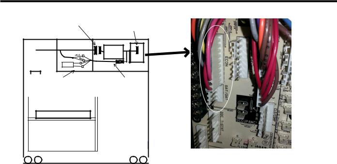
Unplug the 10-pin plug from PL6 from the Central Terminal Board (in control box) and plug into 10-pin plug from W7220
Plug 10-pin plug from W7220 into ECONO terminals on Central Terminal Board
Indoor Blower |
|
ECONO |
|
|
|
Section |
W7720 |
See |
Picture |
||
|
|
|
|||
|
|
|
|
||
|
|
|
|
|
|
SAT |
BRN |
Control box |
Central |
|
|
|
ORN |
TermBrd |
|
|
|
|
|
|
|
||
|
|
|
|
|
|
|
PL6 |
|
Connect SAT sensor and Pink |
48TMHSRSE--A20 |
|
|
|
|
|
and Violet wires from PL6 to |
harness with 4- pin |
|
|
|
|
||
|
|
|
|
plug |
|
|
|
|
|
the 48TMHSRSE— A20 |
|
|
|
|
|
harness. |
|
|
|
|
|
|
|
Economizer X
|
|
|
D. |
Connect other 10-pin plug from W7220 controller into ECONO |
|
|
|
|
|||
|
|
|
|
terminals on CTB. See picture above. |
|
|
Fig. 7 - Harness Detail |
|
|||
|
E. |
Connect 4-pin plug from the W7220 controller to the 4-pin |
|||
WIRING INSTRUCTIONS FOR 1 AND 2 SPEED UNITS: |
|
48TMHSRSE—A20harnessprovidedwitheconomizeraccessory. |
|||
F. |
Route 48TMHSRSE—A20 harness back to the indoor blower |
||||
A. Install W7220 (with harnesses attached) in unit control box. See |
|||||
|
section of the unit. |
||||
wiring diagram in instructions. |
G. |
Mount Supply (or Mixed) Air Temperature sensor, and connect |
|||
B. Unplug econo harness from PL6 with 10-pin plug shown above in |
|
Brown and Orange wires from harness to the SAT. |
|||
picture, from Central Terminal Board (CTB). |
H. |
Connect Pink and Violet wires from 48TMHSRSE—A20 harness |
|||
C. Attach 10-pin plug disconnected from (CTB) to 10pin plug |
|
to the Pink and Violet wires from PL6 economizer harness |
|||
harness from W7220 controller. |
|
|
|||
4

48TMHSRSE--A20
Harness
If using HH57AC081 outside air enthalpy accessory, the OAT must be removed and disconnected. Set sensor dip-switches, see Table 11.
Fig. 8A - Typical EconoMi$er X Wiring Diagram For 1 and 2 Speed Units
(2 Speed Diagram Shown)
5
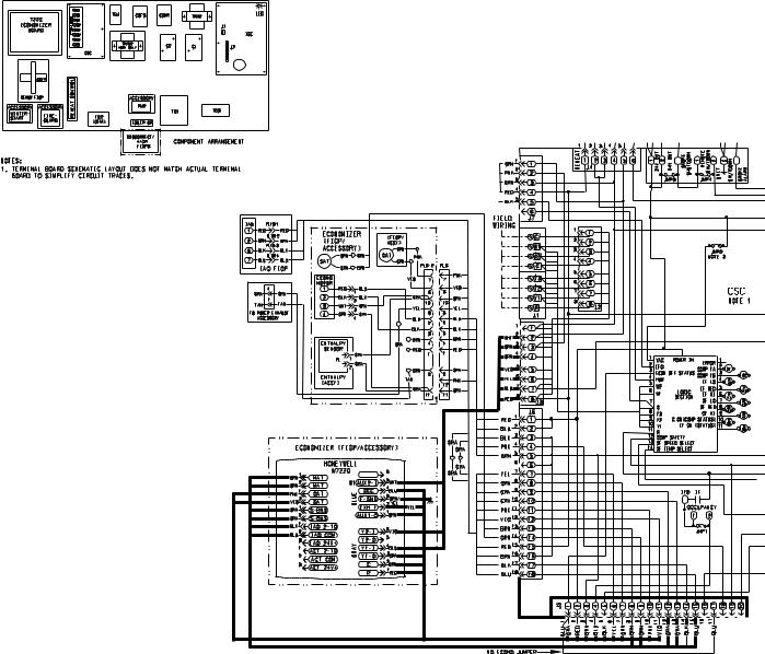
Fig. 8B - Typical EconoMi$er X Wiring Diagram For 3 Speed Units (48/50LC 07-12) (See 3 Speed Unit Instructions for Complete Diagram)
NOTES:
1.Wires shown in bold are part of 48LCHSRADH--A00 harness which is provided with 48/50LC 07-12 3 speed units.
2.Harness 48TMHARSE--A20 which is provided with economizer accessory is not used on 3 speed units.
6
 Loading...