


WELCOME TO A NEW GENERATION OF COMFORT
Congratulations! In light of rising energy costs, the 58MXA, 58MCA, 58MTA, and WeatherMaker Infinity, Multipoise, GasFired Condensing Furnaces are among the soundest investments today’s homeowner can make.
Your new furnace is truly a triumph of technology in home heating. A revolutionary design employs 2 heat exchangers to “squeeze” out the maximum amount of heat from the fuel consumed. In fact, your new furnace is so efficient, over 90%* of the heat generated during combustion is captured and delivered inside your home. That is more that a 33%* increase in heating efficiency over conventional furnaces.
These are among the most energy-efficient furnaces you can buy today. They also are among the safest and most dependable. We are proud of the technological advances incorporated into the design of these furnaces.With only minimal care, your new furnace will deliver many years of money-saving home comfort and enjoyment. Spend just a few minutes with this manual to learn the operation of your new furnace and the small amount of maintenance it takes to help keep it operating at peak efficiency year after year.
*The output capacity and any representations of efficiency for this furnace are based on standard Department of Energy test procedures.
INSTALLATION DATA
Date Installed
Dealer Name
Address
City
State Zip
Telephone
FURNACE
Product No.
Model No.
Serial No.
SPLIT-SYSTEM
OUTDOOR UNIT:
Product No.
Model No.
Serial No.
INDOOR COIL:
Product No.
Model No.
Serial No.
|
|
|
|
® |
|
|
|
• • • • • • • • • • |
• |
|
• • |
• |
• |
need art |
U L T R A H I G H E F F I C |
NI |
E |
CN C |
EY |
|
|
G A S F U R N A |
|
|
|
|
|
1
MODELS 58MXA (SHOWN) AND 58MCA FIXED-CAPACITY FURNACES
2
MODEL 58MVP
VARIABLE-CAPACITY
AND MODEL 58MTA
TWO-STAGE FURNACES
2
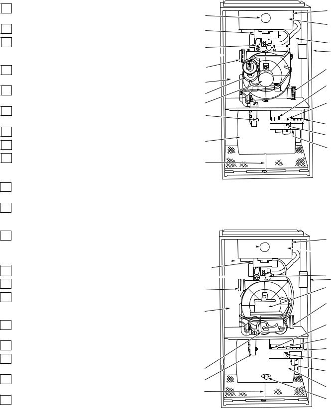
FURNACE COMPONENTS
1Combustion-air intake connection to ensure contami- nant-free air (right or left side).
2Burner sight glass for viewing burner flame.
3Burner assembly (inside). Operates with energy-saving pilot, inshot burners, and hot surface igniter for safe, dependable heating.
4Redundant gas valve. Safe, efficient. Features 1 gas control with 2 internal shutoff valves.
5Vent outlet. Uses PVC pipe to carry vent gases from the furnaces combustion system (right or left side).
6Inducer motor. Pulls hot flue gases through the heat exchangers, maintaining negative pressure for added safety.
7Blower access panel safety interlock switch.
8Air filter and retainer.
9Condensate drain connection. Collects moisture condensed from burned gases for disposal into home drain system.
10Heavy-duty blower. Circulates air across the heat exchangers to transfer heat into the home.
11Secondary condensing heat exchanger (inside). Wrings out more heat through condensation. Constructed with Polypropylene-laminated steel to ensure durability.
12Primary serpentine heat exchanger (inside). Stretches fuel dollars with the S-shaped heat-flow design. Solid construction of corrosion-resistant aluminized steel means reliability.
13Control center.
143-amp fuse provides electrical and component protection.
15Light emitting diode (LED) on control center. Code lights are for diagnosing furnace operation and service requirements.
16Pressure switch(es) ensure adequate flow of flue products through furnace and out vent system.
17Rollout switch (manual reset) to prevent overtemperature.
18Junction box for 115-v electrical power supply. (May be on right or left side)
19Transformer (24v) behind control center provides lowvoltage power to furnace control center and thermostat.
20Limit switch (manual reset) on 58MVP only.
2 |
17 |
|
3 |
||
1 |
||
|
||
4 |
12 |
|
|
18 |
|
5 |
5 |
|
11 |
14 |
|
16 |
15 |
|
6 |
||
|
||
9 |
need art |
|
|
13 |
|
10 |
7 |
|
19 |
||
|
||
8 |
|
3
MODELS 58MXA, 58MCA, AND 58MTA FURNACES (UPFLOW POSITION)
17
2 
 3
3
12 
1
|
4 |
5 |
618 |
|
|
11 |
5 |
|
|
15 |
|
|
14 |
|
|
13 |
|
16 |
7 |
|
19 |
||
9 |
||
10 |
||
8 |
||
20 |
||
|
4
MODEL 58MVP
FURNACE (UPFLOW POSITION)
3
IMPORTANT FACTS
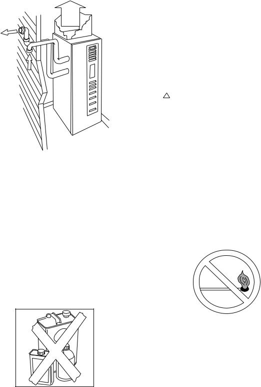
Your gas furnace uses air from outside the home for combustion and venting. It is not to be installed using in-house air. Therefore, both pipes must terminate outside the structure and must not be obstructed in any way.
This furnace contains SAFETY DEVICES which must be MANUALLY RESET. If the furnace is left unattended for an extended period of time, have it checked periodically for proper operation. This precaution will prevent problems associated with no heat, such as frozen water pipes, etc. See “Before You Request a Service Call’’ section in this manual.
|
SAFETY CONSIDERATIONS |
|
|
Installing and servicing heating equipment can be hazard- |
|
|
ous due to gas and electrical components. Only trained and |
|
|
qualified personnel should install, repair, or service heating |
|
|
equipment. |
|
|
Untrained personnel can perform basic maintenance func- |
|
|
tions such as cleaning and replacing air filters. All other |
|
|
operations must be performed by trained service person- |
|
|
nel. Observe safety precautions in this manual, on tags, and |
|
|
on labels attached to the furnace, and other safety precautions |
|
|
that may apply. |
|
|
Recognize safety information. This is the safety-alert sym- |
|
|
bol ! . When you see this symbol on the furnace and in |
|
|
instructions or manuals, be alert to the potential for personal |
|
|
injury. |
|
|
Understand the signal words—DANGER, WARNING, and |
|
|
CAUTION. These words are used with the safety-alert sym- |
|
|
bol. DANGER identifies the most serious hazards which |
|
|
will result in severe personal injury or death. WARNING |
|
|
signifies hazards which could result in personal injury or |
|
|
death. CAUTION is used to identify unsafe practices which |
|
|
would result in minor personal injury or product and prop- |
|
5 |
erty damage. NOTE is used to highlight suggestions which |
|
will result in enhanced installation, reliability or operation. |
||
To minimize the possibility of serious personal injury, fire, |
||
|
||
furnace damage, or improper operation; carefully follow |
STARTING YOUR FURNACE |
|
these safety rules: |
||
• Keep the area around your furnace free of combustible |
Instead of a continuously burning pilot flame which wastes |
|
materials, gasoline, and other flammable liquids and vapors. |
valuable energy, your furnace uses an automatic, hot surface |
|
• Do not cover the furnace, store trash or debris near it, or |
ignition system to light the burners each time the thermostat |
|
starts your furnace. Follow these important safeguards: |
||
in any way block the flow of fresh air to the unit. |
||
|
||
• A furnace installed in an attic or other insulated space |
|
|
must be kept free and clear of insulating material. Examine |
|
|
the furnace area when installing the furnace or adding more |
|
|
insulation. Some materials may be combustible. |
|
|
NOTE: Do not use this furnace if any part has been under |
|
|
water. Immediately call a qualified service technician to |
|
|
inspect the furnace and to replace any part of the control |
|
|
system and any gas control which has been under water. |
|
NOTE: The qualified installer or agency must use only factory-authorized replacement parts, kits, and accessories when modifying this product.
7
•Never attempt to manually light the burners with a match or other source of flame.
•Read and follow the operating instructions on the furnace, especially the item that reads as follows:
Wait 5 minutes to clear out any gas. Then smell for gas, including near the floor. If you smell gas, STOP! Follow “B’’ in the safety information above on this furnace label. If you don’t smell gas, go to the next step.
• If a suspected malfunction occurs with your gas control
6system, such as the burners do not light when they should, refer to the shutdown procedures on the furnace, or in the “Shutting Down Your Furnace” section and call your dealer as soon as possible.
4
! WARNING
If overheating occurs or the gas valve fails to shut off the gas supply, turn off the manual gas valve to the furnace BEFORE turning off the electrical supply. (See Fig. 9.) Failure to follow this warning could result in a fire or explosion, and personal injury or death.
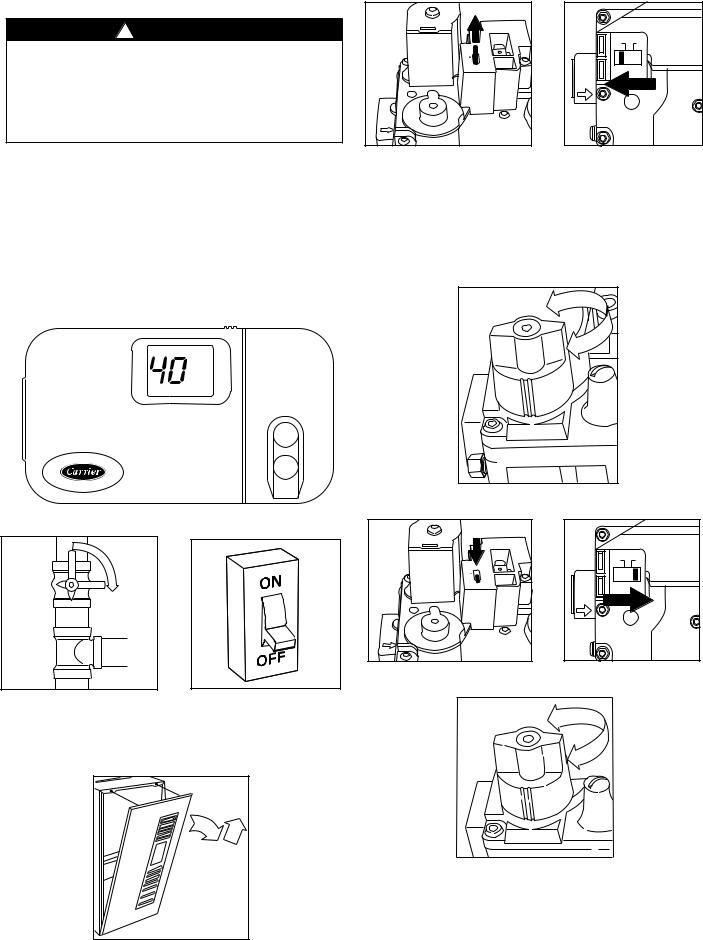
• CHECK AIR FILTER: Before attempting to start your furnace, be sure the furnace filter is clean and in place. See “Performing Routine Maintenance” section in this manual. Then proceed as follows:
STEPS FOR STARTING YOUR FURNACE
1.Set your room thermostat to the lowest temperature setting. (See Fig. 8.)
2.Close the external manual gas valve. (See Fig. 9.)
®
8
CL
O
S
E
9 |
10 |
3.Turn OFF electrical supply to the furnace. (See Fig. 10.)
4.Remove control access door. (See Fig. 11.)
O |
M |
1 |
OFF |
ON |
|
P |
3 |
|
|
F |
|
|
|
|
|
|
|
|
|
F |
|
2 |
OR |
|
|
C |
|
||
|
ON |
|
|
|
|
|
|
|
12 |
5.The gas valve will have EITHER a control knob or control switch to turn off and on. Turn the control knob or switch on the gas valve to the OFF position and wait
5 minutes. (See Fig. 12 or 13.)
6.After waiting 5 minutes, turn the control knob or switch on the gas valve to the ON position. (See Fig. 14 or 15.)
|
|
|
F |
|
|
|
|
OF |
|
|
|
|
|
|
|
13 |
|
|
M |
1 |
|
OFF |
ON |
O |
P |
3 |
|
||
F |
|
|
|
|
|
F |
C |
2 |
OR |
|
|
|
|
|
|||
|
ON |
|
|
|
|
|
|
|
|
|
|
14
11 |
5
ON
15
 Loading...