


Deluxe 58MVP
Visit www.carrier.com
58MVP
Variable-Speed 2-Stage
Electronic Condensing Furnace
Troubleshooting Guide
NOTE: Read the entire instruction manual before starting the
installation.
SAFETY CONSIDERATIONS
INDEX
PAGE
Instructions .....................................................................................1
Example..........................................................................................2
Sequence of Operation................................................................1-5
Self-Test Mode..........................................................................2
Heating Mode............................................................................2
Heating Mode-Two Stage.........................................................2
Emergency Heat Mode..........................................................2-3
Cooling Mode ...........................................................................3
Heat Pump Mode...................................................................3-4
Continuous Fan Mode ..............................................................4
Component Test.....................................................................4-5
Bypass Humidifier Mode..........................................................5
Dehumidification Mode............................................................5
Zone Mode................................................................................5
Start Here........................................................................................6
Service Label/Fault Code Instructions.......................................7-8
Improper Operation With No Flashing Fault Code......................9
Not Enough Cooling Airflow......................................................10
High-Fire Temperature Rise Too Low (Cold Blow)..................11
LEDs 1, 2, 3, or 4 On Solid...................................................11-12
RED LED2 Flashing....................................................................12
Fault Code 11—No Fault in Recent History Display ................13
Fault Code 12—Blower Calibration Lockout........................13-15
Fault Code 13—Limit Switch Lockout..................................15-16
Fault Code 14—Ignition Lockout................................................17
Fault Code 21—Invalid Model Selection....................................17
Fault Code 22—Set Up Error......................................................18
Fault Code 23—Invalid Blower Airflow Selection....................18
Fault Code 24—Secondary Voltage Fuse Is Open................19-20
Fault Code 31—High-Pressure Switch Fault.........................21-22
Fault Code 32—Low-Pressure Switch Fault .........................23-24
Fault Code 33—Limit Switch Fault.......................................24-25
Fault Code 34—Ignition Proving Fault .................................26-27
Fault Code 41—Blower Outside Valid Speed Range...........27-28
Fault Code 42—Inducer Outside Valid Speed Range...........29-30
Fault Code 43—Pressure Switch Calibration Fault...............30-31
Fault Code 44—Blower Calibration Fault..................................32
Cleanup and Start-Up Instructions ..............................................33
APPENDIX A—Board Layout & Wiring Schematic ...........34-35
APPENDIX B—Isolation Circuits ..............................................36
APPENDIX C—Pressure Check Diagram..................................36
APPENDIX D—Quick Motor Test Procedure......................37-39
APPENDIX E—Variable-Speed Condensing Furnace Duct Static
and Blower Operation.............................................................40-44
APPENDIX F—Quick Reference Information...........................45
APPENDIX G—Thermostat Staging Algorithm...................46-47
This guide uses your expertise and observations to lead you to the
INSTRUCTIONS
trouble spot as efficiently as possible. This is only intended as a
guide and should not be used blindly. Your experience and
expertise are of high value when troubleshooting this unit. Do not
disregard all of your instincts.
The microprocessor furnace control was designed with diagnostic
capabilities built in. LEDs are used to flash a fault code which will
lead you to 1 of the subsections as listed in the Index.
You should ALWAYS begin in the START HERE subsection
(see Index for page number) which will guide you to the
appropriate subsection where a minimal number of steps will be
used to correct the problem. If you are very experienced at how
this furnace operates and you suspect the problem is either the
blower motor, inducer motor,or furnace controlboard, youcan use
the quick motor test procedure at the end of the troubleshooting
guide to isolate the problem or direct you to appropriate section in
main troubleshooting guide.
Once in a subsection, read the statement or question. A statement
will have a number in the "GO TO" column. Do whatever the
statement says, then proceed to step indicated in the "GO TO"
column.
If the step is a question (a question will have a number in the
"YES" or "NO" column), answer it "YES" or "NO." If the answer
is "YES," go to step indicated in "YES" column. If the answer is
"NO," go to step indicated in "NO" column.
Let’s try our guide out using the EXAMPLE section below, and
see how it works. Suppose that the problem is a defective
low-pressure switch (for example will not make). This is an
internal problem and cannot simply be seen. We go to the START
HERE section to Step 1.
Additional Service Tools are available for current variable speed
condensing furnaces. The Advanced Product Monitor Kit
KGAFP0101APM includes a harness and diskette that allows
communication with the control board through a personal computer (RS-485 adapter required). The ICM Motor Simulator Kit
KGASD0101FMS is a plug-in device to help trooubleshoot ICM
inducer and blower motors and control boards. Reference price
pages for current kit numbers.
SEQUENCE OF OPERATION
Furnace control must be grounded for proper operation, or
control will lock out. Control is grounded through green wire
routed to gas valve and burner box screw.
Using schematic diagram (see Appendix A), follow sequence of
operation through different modes. This furnace has a new control
system. Read and follow wiring diagram carefully.
NOTE: If 115-v power supply to furnace or blower access panel
switch is interrupted during a call for heat, blower operates at
low-heat speed for 60 sec when power is restored before heating
cycle is resumed.
Manufacturer reserves the right to discontinue, or change at any time, specifications or designs without notice and without incurring obligations.
Book 1 4
Tab 6a 8a
PC 101 Catalog No. 535-754 Printed in U.S.A. Form 58MVP-8SM Pg 1 9-99 Replaces: 58MVP-6SM

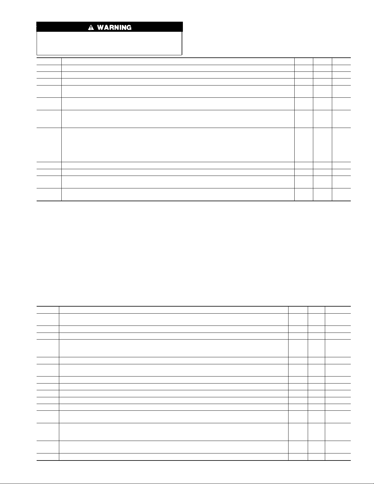
EXAMPLE
Start Here Section
STEP ACTION YES NO GO TO
1. Step 1 tells us to record status of LEDs 1-4 and go to Step 2. — — 2
Step 2 asks the question, "Are any LEDs flashing?". If low-pressure switch was defective, a low-
2.
pressure switch fault code would be flashing, so the answer is "YES." We go to Step 5.
Step 5 asks the question, "Is RED LED2 flashing?". If low-pressure switch was defective, a low-
5.
pressure switch fault code would be flashing, so the answer is "NO". We go to Step 7.
7. Step 7 tells us to go to low-pressure switch fault subsection. — — INDEX
53 —
67 —
Step 1—Self-Test Mode
The control center goes through a brief self test whenever 115-v or
24-v power is interrupted. The self test takes approximately 2 sec
to complete. After power is restored, red (microprocessor) LED
briefly comes on. Thengreen LEDcomes onfor 1sec, followedby
1 sec where both yellow and green LEDs are on. During this time,
the microprocessor is checking itself.
Step 2—Heating Mode
When thermostat calls for heat, R-W/W1 circuit closes.
1. Prepurge period—Theinducer motor is turned onand slowly
comes up to speed. When low-pressure switch closes, inducer
motor RPM is noted by microprocessor, and a 25 sec prepurge
period begins. The RPM is used to evaluate vent system
resistance. This evaluation is then used to determine required
RPM necessary to operate inducer in low-heat mode.
NOTE: The heat cycle can start in either high or low heat. If a
high-heat cycle is initiated, the inducer continues increasing its
speed after low-pressureswitch closes. When high-pressure switch
closes, inducer motor RPM is noted by microprocessor before the
25 sec prepurge period begins. The RPM is used to evaluate vent
system resistance. This evaluation is then used to determine
required RPM necessary to operate inducer in high-heat mode.
2. Humidifier (HUM)—The HUM terminal is energized when-
ever the inducer prepurge period is completed.
3. Ignitor warm up—At end of prepurge period, the hot surface
ignitor (HSI) is energized for a 17-sec HSI warm-up period.
4. Ignition sequence—After HSI ignitor warm-up period is
completed, the gas valve opens, permitting gasflow to burners
where it is ignited. After 5 sec, the HSI is de-energized and a
2-sec flame-sensing period begins.
NOTE: The initial heat mode after 115-v or 24-v power interruption will be LOW HEAT. Low heat remains energized for 16
minutes before high heat is initiated, providing thermostat is still
calling for heat.
After the initial cycle, the microprocessor evaluates the length of
low- and high-heat operating times and calculates optimum length
of low and high heat for next heat cycle. This accommodates the
heat load requirement seen as a resultof thermostat operating time.
See Appendix G for details on thermostat staging algorithm.
5. Flame sensing—When burner flame is sensed, the control
center holds gas valve open and begins blower on delay
period.
NOTE: Ignition sequence repeats 3 additional times before a
lockout occurs. Lockout automatically resets after 3 hr, or can be
manually reset by turning 115-v or 24-v power off (not at
thermostat) for 3 sec minimum, then turning on again.
6. Inducer speed reduction—If cycle starts in low heat, inducer
speed reduces slightly after the flame sense. If cycle starts in
high heat, inducer speed increases 15 sec after flame sense.
The reduction in speed in low heat is to optimize combustion
for maximum efficiency.
7. Blower on delay—The blower starts 60 sec after flame sense
if cycle started in low heat or 35 sec after flame sense if cycle
started in high heat.
NOTE: The blower starts at approximately 400-500 RPM. After
20 sec, the motor is turned offfor 1/10 of a sec where a coast down
calibration is done to evaluate resistance of the conditioned air
duct system. The microprocessor then determines blower RPM
required to provide proper airflow for heating mode.
8. Electronic Air Cleaner—The EAC-1 terminal is energized
whenever the blower operates.
9. Blower offdelay—When thermostat issatisfied, the R-W/W1
signal is terminated, de-energizing gas valve (stopping gas
flow to burners) and HUM terminal is de-energized.
The blower reduces its speed to low-heat RPM. The blower
and EAC remain operating 90, 135, 180, or 225 sec (depending on blower offtime selection).The furnaceis factoryset for
a 90 sec blower off delay.
10. Post purge—The inducer continues operating for 15 sec after
gas valve is de-energized.
Step 3—Heating Mode—Two Stage
The control center provides 2-stage heating using a single-stage
thermostat. The control center maximizes comfort while optimizing efficiency to meet the demands of the conditioned area when
a thermostat R-W/W1 signal is received.
If thermostat control over furnace staging is desired, a 2-stage
thermostat can be used. When control center receives a thermostat
R-W/W1 and R-W2 signal, high heat is energized and when
R-W/W1 signal is received, low heat is energized. This method
overrides microprocessor control of high or low heat.
NOTE: When using 2-stage thermostat operation with R-W/W1
and R-W2 signals, setup switch SW-2 MUST be in ON position.
The heat cycle operates as stated in Heating Mode section.
To allow for greater comfort, a 2-stage thermostat control is
recommended when zone systems are used.
Step 4—Emergency Heat Mode
NOTE: The furnace should not be operated in emergency heat
mode for extended periods of time. Operation is only recommended to provide heat until replacement components can be
obtained or fault resolved.
In this mode, the microprocessor is bypassed and the motors
operate at full speed with high-heat operation. The heat exchangers, motors, and electronics can be overstressed and may reduce
the life of the components if operated for an extended period.
NOTE: No safeties are bypassed when using emergency heat
mode.
Emergency heat mode can be selected using setup switch SW-4.
SW-4 should be used when a fault condition exists or difficult to
resolve problems occur. This allows heating until the fault can be
corrected.
2

In emergency heat mode, the normal heat mode outlined in
Heating Mode section is not followed. The following sequence
will occur:
When thermostat calls for heat, the R-W/W-1 circuits close.
1. Prepurge period—The inducer motor is turned on IMMEDI-
ATELY operating at maximum speed, closing low- and
high-pressure switches. Prepurge begins 25 sec after highpressure switch closes.
2. Blower on—The blower motor is turned on IMMEDIATELY
and slowly increases to maximum speed as soon as a call for
heat is received. No blower calibration occurs.
3. Electronic Air Cleaner—The EAC-1 terminal does not
operate in emergency heat mode.
4. Humidifier—The HUM terminal is energized IMMEDI-
ATELY.
5. Ignitor warm up—The HSI is energized for a 17 sec
warm-up period after prepurge period is completed.
6. Ignition sequence—After HSI warm-up period has com-
pleted, the gas valve is energized, permitting gas flow to
burners where it isignited. After 5sec, theHSI isde-energized
and a 2-sec flame-sensing period begins.
NOTE: Emergency heat mode only operates in high heat.
7. Flame sensing—When burner flame is sensed, control center
holds gas valve open. If burner flame is not sensed, control
center de-energizes gas valve and ignition sequence is repeated.
NOTE: Ignition sequence repeats 3 additional times before lockout occurs. Lockout automatically resets after 3 hr, or can be
manually reset by turning 115-v or 24-v power off (not at
thermostat) for 3 sec minimum, then turning on again. Fault codes
will not flash in emergency heat mode.
8. Blower offdelay—When thermostat issatisfied, the R-W/W1
signal is terminated, de-energizing gas valve (stopping gas
flow to burners) and HUM terminal is de-energized. In
addition, blower stops immediately.
9. Post purge—Post purge does NOT occur. The inducer stops
immediately.
Step 5—Cooling Mode
When thermostat calls for cooling, the R-G and R-Y/Y2 circuits
close.
1. Cooling unit—The cooling unit starts when thermostat R-Y
signal is received.
2. Blower on—The control center starts blower immediately
when it receives an R-Y/Y2 and R-G signal. The blower starts
at approximately 400-500 RPM. After 20 sec, the blower is
turned off for 1/10 of a sec where a coast down calibration is
done to evaluate resistance of the conditioned air duct system.
The microprocessor then determines blower RPM required to
provide selected cooling airflow.
NOTE: In cooling mode, themicroprocessor adjusts blower RPM
to operate at 400 CFM per ton as selected on the A/C setup
switches. Airflow will be reduced to 340 or 315 CFM per ton,
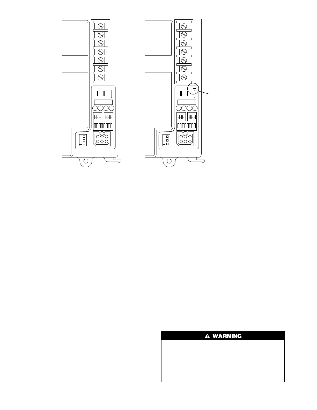
depending on board style (See Fig. 1), when a dehumidification
demand exists. See Air Conditioning Setup Switches section in
Installation, Start-Up and Operating Instructions for details. There
is also a chart on schematic in Appendix A.
NOTE: If Y/Y2 thermostat lead is not connected to furnace
control center, blower motor operates in continuous fan speed and
indoor coil freeze-up may occur.
3. Electronic Air Cleaner—The EAC-1 terminal is energized
whenever blower operates.
4. Cooling unit—The cooling unit stops when thermostat R-Y
signal is terminated.
5. Blower off delay—When thermostat is satisfied, the R-Y/Y2
and R-G signals are terminated, and blower remains operating
for 90 sec. On newer style control boards (See Fig. 1), the
blower airflow will drop by 21 percent during the off-delay
period when the DE jumper is connected. The DE jumper is
only removed to enable the DEHUM input for use with a
thermidistat or humidistat for dehumidification purposes.
Step 6—Heat Pump Mode
When furnace is operating in heat pump heating mode, R-Y/Y2
and R-G circuits are closed energizing heat pump, and blower
operates at cooling speed. When heat pump defrost is required,
R-W/W1 circuits close starting gas heat cycle, and blower adjusts
to low-heat speed.
1. Prepurge period—Theinducer motor is turned onand slowly
comes up to speed. When low-pressure switch closes, inducer
motor RPM is noted by microprocessor, and a 25 sec prepurge
period begins. The RPM is used to evaluate vent system
resistance. This evaluation is then used to determine required
RPM necessary to operate inducer in low-heat mode.
NOTE: The heat cycle can start in either high or low heat. If a
high-heat cycle is initiated, inducer continues increasing its speed
after low-pressure switch closes. When high-pressure switch
closes, inducer motor RPM is noted by microprocessor before the
25 sec prepurge period begins. The RPM is used to evaluate vent
system resistance. This evaluation is used to determine required
RPM necessary to operate inducer in high-heat mode.
2. Humidifier—The HUM terminal is energized whenever in-
ducer prepurge period is completed.
3. Ignitor warm up—After prepurge period, HSI is energized
for 17 sec.
4. Ignition sequence—After HSI warm-up period is completed,
the gas valve is energized, permitting gas flow to the burners
where it is ignited. After 5 sec, the HSI is de-energized and a
2-sec flame-sensing period begins.
5. Flame sensing—When burner flame is sensed, control center
holds gas valve open.
If burner flame is not sensed, control center de-energizes gas
valve and ignition sequence is repeated.
6. Blower off period—Ten sec after gas valve is energized, the
blower stops for 25 sec to allow heat exchangers to warm up.
7. Blower on delay—After blower off period, blower starts.
NOTE: The blower starts at approximately 400-500 RPM. After
20 sec, the motor is turned offfor 1/10 of a sec where a coast down
calibration is done to evaluate resistance of the conditioned air
duct system. The microprocessor then determines blower RPM
required to provide proper airflow for heating mode.
8. Electronic Air Cleaner—The EAC-1 terminal is energized
whenever blower operates.
9. Inducer speed reduction—If cycle starts in low heat, inducer
speed reduces slightly after the flame sense. If cycle starts in
high heat, inducer speed increases 15 sec after flame sense.
The reduction in speed in low heat is to optimize combustion
for maximum efficiency.
10. Call for heat terminated—When the call for heat is satisfied,
the R-W/W1 signal is terminated, de-energizing gas valve
(stopping gas flow to burners) and HUM terminal is deenergized.
a. R-W/W1 signal terminated with R-Y/Y2 and R-G still
present—The blower changes its speed to cooling RPM.
3
SEC-2
SEC-1
W/W1 Y/Y2 HUMRG
24V
W2 Com
DEHUM
SEC-2
SEC-1
DE
DEHUM
W/W1 Y/Y2 HUMRG
24V
W2 Com
DE CONNECTION
WITHOUT DE
CONNECTION
Fig. 1—Variable Speed Furnace Control
b. R-W/W1 with R-Y/Y2 and R-G signals terminated—
The blower continues to operate completing a normal
blower off delay.
11. Post purge—The inducer continues operating for 15 sec after
gas valve is de-energized.
Step 7—Continuous Fan Mode
1. Operating with continuous fan only.
a. Call for continuous fan—The thermostat closes R-G
circuit.
b. Blower on—The blower starts immediately.
NOTE: The blower starts at approximately 400-500 RPM. After
20 sec, the motor is turned offfor 1/10 of a sec where a coast down
calibration is done to evaluate resistance of the conditioned air
duct system. The microprocessor then determines blower RPM
required to provide proper airflow for heating mode.
NOTE: The continuous fan speed is the same as low-heat speed
unless it is field adjusted to another desired airflow. See Continuous Fan Setup Switches section in Installation, Start-Up, and
Operating Instructions for details. There is also a chart on
schematic diagram shown in Appendix A.
c. Electronic Air Cleaner—The EAC-1 terminal is ener-
gized whenever blower operates, regardless of operating
mode.
2. Operating with continuous fan (R-G) and call for heat
(R-W/W1) is received—Same as heat pump mode except
blower on delay is 10 sec less than the heat mode. After call
for heat (R-W/W1) is terminated, the blower remains operating at low-heat speed for selected blower off delay before
resuming continuous fan speed.
3. Operating with continuous fan (R-G) and call for cooling
(R-Y/Y2) is received—See Cooling Mode section. After call
WITH DE
CONNECTION
A98293
for cooling (R-Y/Y2) is terminated, the blower remains
operating at cooling speed for 90 sec before resuming continuous fan speed.
Step 8—Component Test
All components are functionally operated except gas valve with
component test feature.
This feature helps diagnose a system problem in case of a
component failure.
NOTE: Setup switch SW-1 MUST be in OFF position or Fault
Code 22 (setup error) will occur.
NOTE: NO thermostat signal may be present at control center,
and all blower time delay off periods must be completed.
To initiate component test feature, proceed with the following:
1. Leave 115-v power to furnace turned on.
2. Remove main furnace door.
3. Remove blower access panel.
4. Turn setup switch SW-6 to ON position.
5. Manually close blower access panel door switch.
On some models, blower access paneldoor switch opens only
24-v power to control center. No component operation can
occur. The 115-v power is still present at control center,
transformer, inducer motor, and main blower motor. Caution
must be taken when manually closing this switch for service
purposes. Failure to follow this warning could result in
personal injury or death.
4
When items 1-5 have been completed, the following will occur:
1. The control center goes through a brief self test. This self test
takes approximately 2 sec to complete. After door switch is
closed, red (microprocessor) LED briefly comes on. Then
green LED comes on for 1 sec, followed by 1 sec where both
green and yellow LEDs are on. During this time, the microprocessor is checking itself.
2. Inducer motor operates for 20 sec at low speed, operates 20
sec at high speed, then turns off.
3. Hot surface ignitor is energized for 15 sec, then de-energized.
4. Main blower motor operates for 20 sec at low speed, operates
for 20 sec at high speed, then turns off.
5. After component operation test is completed, 1 or more fault
codes (11, 22, 41, or 42) will flash. See service label on back
of main furnace door or Fig. 1 for explanation of fault codes.
NOTE: To repeat component test, turn setup switch SW-6to OFF
and then back to ON.
After component test, perform the following:
1. Release blowerpanel access door switch and turn setup switch
SW-6 to OFF position.
2. If applicable, replace blower access panel and check LED
status by removing plug in blower access panel.
3. Reinstall main furnace door if all LEDs are off, indicating
furnace is ready to operate when a signal from thermostat is
received.
Step 9—Bypass Humidifier Mode
When setup switch SW-3 BPH is in ON position, RPM calculated
for low heat is multiplied by 1.15 for all furnace model sizes. This
compensates for increased return-air temperature caused by bypassed air supply.
standard humidistat to do dehumidification since the contacts open
on high humidity, thus removing the 24-v signal to initiate
dehumidification.
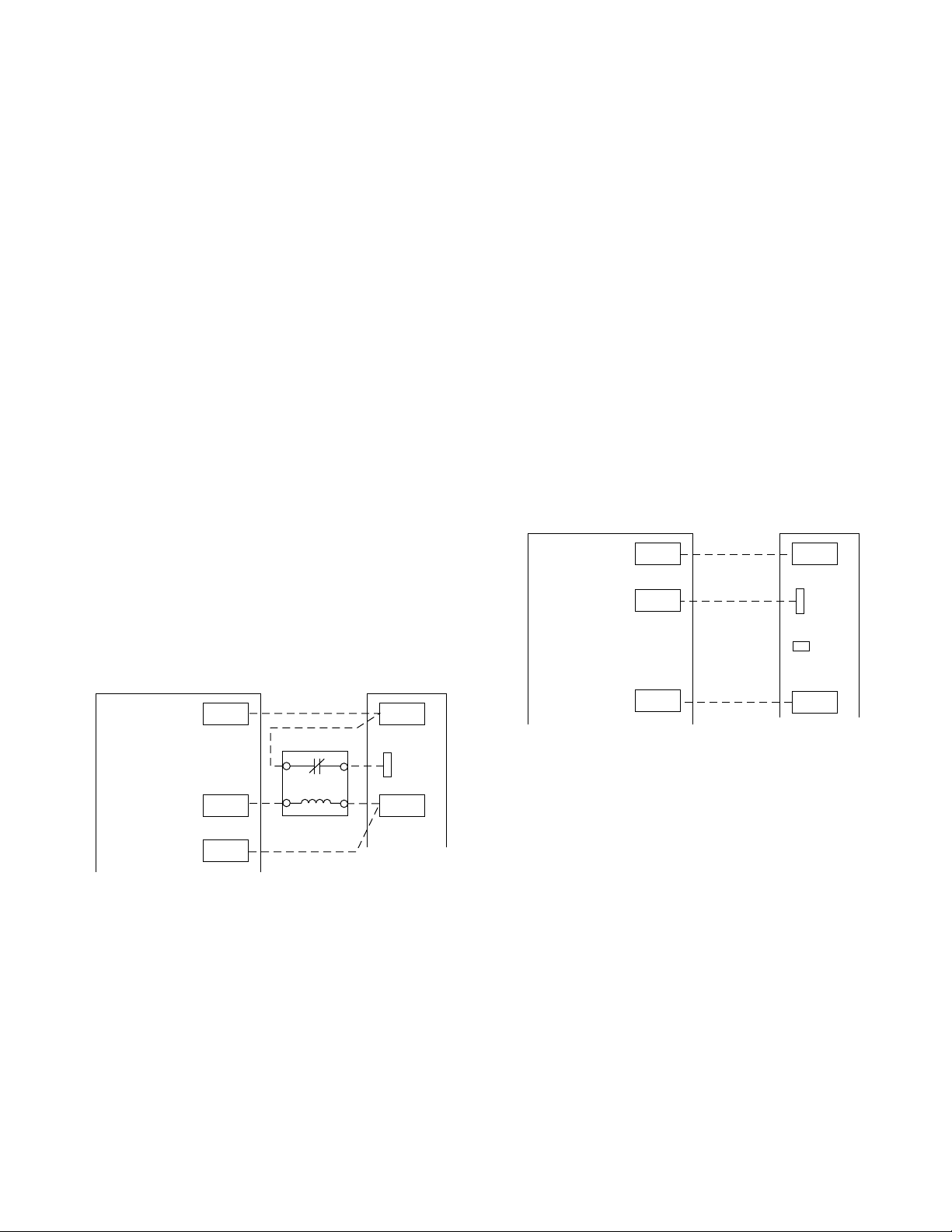
On the older style variable speed furnace controls, a field supplied
relay is required betweenthe thermidistator humidistatcontrol and
furnace. The relay coil is connected between DHUM output on the
thermidistat control and C
humidistat output and C
OM terminal on the furnace control or the
OM terminal on the furnace control. Its
normally closed contact is connected between R and DEHUM
terminals on the furnace control. (See Fig. 1 and Fig. 2). When a
dehumidify demand exists, relay is de-energized, and normally
closed contacts supply 24-v to the furnace DEHUM terminal. As
a result, the furnace control reduces the blower airflow by 15
percent to 340 CFM per ton during continuous fan or cooling
operation.
On newer style variable speed furnace controls, a field supplied
relay IS NOT required. The DEHUM output on the thermidistat
control or the humidistat output is connected directly to the
DEHUM terminal on the furnace control. In addition, the DE
jumper located next to the DEHUM terminal must be removed to
enable the DEHUM input. (See Fig. 1 and Fig. 3). When a
dehumidify demand exists, the furnace control reduces the blower
airflow by 21 percent to 315 CFM per ton during continuous fan
or cooling operation.
VARIABLE-SPEED
THERMIDISTAT
24 VAC HOT
DEHUMIDIFY
RR
DHUM
CONDENSING
FURNACE
DEHUM
VARIABLE-SPEED
THERMIDISTAT
24 VAC HOT
DEHUMIDIFY
24 VAC COMM
Fig.2—Without DE Connection
RR
DHUM
C
CONDENSING
FURNACE
DEHUM
Com
A98294
Step 10—Dehumidification Mode
A dehumidification input is provided via a 1/4-in. male quickconnect terminal labeled DEHUM, located next to the transformer
secondary connections. The DEHUM input acts differently depending on which style of variable speedfurnace control you have.
The older style variable speed furnace control (shown in Fig. 1)
DOES NOT have a DE connection while the newer style variable
speed furnace control (shown in Fig. 1) has a DE connection. The
newer style variable speed furnace control is expected to be
available by mid 1998. Both of these variable speed furnace
controls function the same except the DEHUM logic is reversed.
This logic reversal has come about from historical use of a
DE
NOTE 1
24 VA C COMM
Fig. 3—With DE Connection
C
NOTE 1 - Remove DE Connection
To Enable DEHUM Input
Com
A98295
This blower speed reduction compensates for high humidity
conditions during cooling operation on all furnace model sizes.
Reference Thermidistat™ Control Installation, Start-up, and Operating Instructions for further details.
Step 11—Zone Mode
When setup switch SW-5 MZ is in ON position, blower motor
control is the same as above except with the following exceptions:
1. While bloweris operatingin either low heat or continuous fan,
the coast down calibration is performed once a minute to
update blower RPM for zone damper position changes during
a given cycle.
NOTE: Boards with date codes of 9506 or later will not perform
a coast down calibration if blower pulse width to blower motor is
greater than 60 percent. This prevents nuisance faults from
occurring when a high continuous fan CFM has been selected.
2. While blower is operating in either high heat or cooling,
blower pulse width to blower motor is frozen when blower
RPM is within 10 percent of calculated blower RPM for 5 sec.
5

START HERE—If a problem exists, the service technician should always begin troubleshooting here.
STEP ACTION YES NO GO TO
Remove furnace door first. DO NOT REMOVE BLOWER ACCESS PANEL! Record status of LED’s
1.
1-4. See Service Label/Fault Code Instructions (Fig.4).
2. Are any LEDs flashing? 53 —
3. Are any LEDs on solid? (Solid means ON continuously.) 4 8 —
4. Go to page number indicated in Index for LEDs 1, 2, 3, or 4 ON SOLID. — — INDEX
5. Is RED LED2 flashing? 67 —
6. Go to page number indicated in Index for RED LED2 FLASHING. — — INDEX
7. Go to page number indicated in Index for subsection covering fault code being flashed. — — INDEX
8. Is power on? (DO NOT cycle power to unit). 10 9 —
9. Turn power on. —— 20
10.
11. Does problem appear to be low cooling airflow? 12 13 —
12. Go to page number indicated in Index for subsection covering NOT ENOUGH COOLING AIRFLOW. — — INDEX
13. Make sure thermostat is calling for heat. — — 14
14. Make sure thermostat fan control is in AUTO position if equipped. — — 15
15. Observe operation of furnace for 20 minutes or until fault occurs. — — 16
16. Does a fault occur? 717 —
17. Is temperature rise below range specified on rating plate when unit is running in high fire? 18 19 —
18.
19. Does furnace operate properly? 31 28 —
20.
21. Disconnect R thermostat lead, then wait until blower motor stops. — — 22
22. Are any LEDs flashing? 24 23 —
23. Are any LEDs on solid? (Solid means ON continuously.) 4 25 —
24. Is RED LED2 flashing? 67 —
25. Put setup switch SW-1 in ON position. — — 26
26.
27. Are LEDs 3 and 4 flashing a Fault Code 11? 29 30 —
28.
29. Go to page number indicated in Index for CLEANUP AND START-UP INSTRUCTIONS. — — INDEX
30. Go to page number indicated in Index for subsection covering first fault code flashed. — — INDEX
31. Disconnect the R thermostat lead, then wait until blower motor stops. — — 32
32. Put setup switch SW-1 in ON position. — — 33
33.
34. Are LEDs 3 and 4 flashing a Fault Code 11? 35 30 —
35.
Remove blower access panel and depress door switch. Use a piece of tape to hold switch closed.
Wait a few sec for self test before proceeding to next step.
Go to page number indicated in Index for subsection
covering HIGH FIRE TEMPERATURE RISE TOO LOW (COLD BLOW).
Remove blower access panel and depress door switch. Use a piece of tape to hold switch closed.
Wait a few sec for self test before proceeding to next step.
Record fault codes listed in fault history.
NOTE: Read fault codes until they repeat. The last fault code that occurred will flash first followed by the lowest number fault code. (EXAMPLE: 13, 13, 44)
Go to page number indicated in Index for subsection covering NO OPERATION WITH NO FLASHING FAULT CODE.
Record fault codes listed in fault history.
NOTE: Read fault codes until they repeat. The last fault code that occurred will flash first followed by the lowest number fault code. (EXAMPLE: 13, 13, 44)
Go to page number indicated in Index for the CLEANUP AND START-UP INSTRUCTIONS. If this
problem persists on an intermittent basis, replace furnace control board. If problem still persists on
an intermittent basis after replacing furnace control board, contact your distributor.
—— 2
—— 11
— — INDEX
—— 21
—— 27
— — INDEX
—— 34
— — INDEX
6

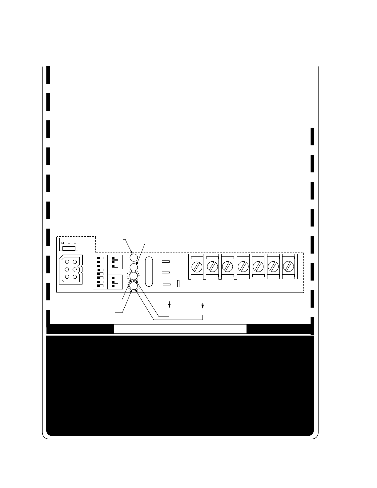
SERVICE
LED CODE
RED LED1 ON
RED LED2 ON
YELLOW LED3 ON
GREE N LE D 4 ON
RED LED2 FLAS HING
EACH OF THE FOLLOWING STATUS CODES IS A TWO DIGIT NUMBER WITH THE FIRST DIGIT
DETERMINED BY NUMBER OF FLASHES OF THE YELLOW LED AND THE SECOND DIGIT
DETERMINED BY NUMBER OF FLASHES OF THE GREEN LED.
11 NO FAULT IN RECENT HISTORY DISPLAY - Indicates no faults have occurred within last five cycles.
To rea d recent fault history put setup switch "SW-1" in th e "ON" position. To clear rec ent fault
history, put setup switch "SW-1" in the "ON" position and jumper thermostat terminals
"R", "W/W1", and "Y/Y2" sim ultaneously until an "11" is flashed.
12 BLOWER CALIBRATION LOCKOUT - Indi ca t es RPM calc ulated for low heat wa s less than 250 RPM
or greater than 1300 RPM on two successive attempts. Auto reset after three hours. Reset
power and refer to fault #44 section.
13 LIMIT SWITCH LOCKOUT - Indicates the occurrence of 10 successive limit trips during high heat
or three successive limit trips during low heat. Auto reset after three hours.
Check for: - Improper or misaligned limit and/or limit shield.
- Improper high or low heat gas input adjustment.
- Stuck high heat solenoid in gas valve.
14 IGNITION LOC KO UT - Control will auto-reset after three hours. Refer to #34.
21 INVALID MODEL SELECTION - Indicates model plug is missing or incorrect. See wiring diagram
for correct connector jumper location.
22 SETUP ERROR - Indicates setup switch "SW-1" or SW-6" is positioned improperly. The following
combinations will cause the fault.
- Th ermostat call with "SW-1" "ON" .
- Th ermostat call with "SW-6" "ON" .
-"SW-1" and "SW-6" both "ON" togeth er.
23 INVALID BLOWER AIRFLOW SELECTION - Indicates improper "A/C" or "CF" switch setting. The 042
and 14 units can deliver 1-1/2 to 3-1/2 tons A/C and 600 to 1400 CFM for continuous fan. The
060 and 20 unit can deliver 2 to 5 tons A/C and 800 to 2000 CFM for continuous fan. If code is
flashing unit will default to closest allowable airflow.
24 SECONDA RY VOLTAGE FUSE IS OPEN
Check for: - Short circuit in secondary voltage (24V) wiring.
31 HIGH PRESS URE SWITCH FAULT - Indicates high pressure switch is closed at call, or in low heat,
or fails to close after call, or opens in high heat.
Check for: - Plugged condensate drain.
- Water in vent piping, possibly sagging pipe.
- Improper pressure switch wiring or pressure switch tubing connections.
- Failed or "Out-of-Cali bration" pr essure switch es.
32 LOW PRESSUR E SWITCH FAULT - Indi cates low p ressure switc h is closed at call, or fails to close
after call, or opens during operation.
Check for: - Plugged condensate drain.
- Water in vent piping, possibly sagging pipe.
- Improper pressure switch wiring or pressure switch tubing connections.
- Failed or "Out-of-Cali bration" pr essure switch es.
33 LIMIT OR FLAME ROLL-OUT SWITCH IS OPEN - Indicates the limit, rollout switch or auxiliary limit
switch is open or the un it is operat ing in high heat only m ode due to t wo successive low he at
limit trips. Check for: - Imp r oper or misaligned limit and/o r limit shield.
- Impro per low heat gas input a djustment.
- Stuck h igh heat solenoid in gas valve.
Furnace is operating in emergency heat.
The microprocessor has malfunctioned. To reset: Put setup switch "
position and jumper thermostat terminals "
the door switch pushed in and power to the unit "
OFF
setup switch in the "
Furnace is operating in high heat.
Furnace is operating in low heat.
Line voltage polarity is reversed.
" position. If
STATUS
R
", "
LED2
reappea rs replace m ain control board.
SW-1
W/W1
", and "
Y/Y2
" simultaneously with
ON
". Disconnect jumper and place
" in the "ON"
A99243a
7
34 IGNITION PROVING FAULT - Control will try three more times before a lockout #14 occurs.
Check fo r: - G as v a lve de fec ti ve o r g a s va lv e t urned "OFF ".
- Defective Hot Surface Ignitor - Manual valve shut-off.
- Low inlet gas pressure - Flame sensor must be ungrounded.
- Gre e n wire MU ST b e connected to furnace sheet meta l.
- Proper flame sense microamps (.5 microamps D.C. minimum, 4.0 - 6.0 nominal in HIGH HEAT)
- Inadequate flame carryover or rough ignition. - Control ground continuity
- Oxid e b u ildup on flame sensor (clean with f ine steel wool.)
41 BLOWER OUTSIDE VALID SPEED RANGE - Indicates the blower is not operating at the calculated
RPM. If this fault occurs in conjunction with fault #44 check wiring to motor otherwise refer to
the trouble-shooting guide.
42 INDU CER OU TSIDE VALID SPEED RANGE - Indicates the inducer is not operating at the
calculated RPM, or has not started within 10 seconds after a call for heat. Check wiring to
motor otherwise refer to the trouble-shooting gu ide.
43 PRESSURE SWITCH CALIBRATION FAULT- Indicates the low and high pressure switch "make"
points during high heat pur g e are not w ithin the ca libration range.
Check for: - Plugged condensate drain.
- Water in vent piping, possibly sagging pipe.
- Improper pressure switch wiring or pressure switch tubing connections.
- Failed or "Out of Calibration" pressure switches.
44 BL OWER CALI BRATIO N FAULT - Indicates the calculated blower speed is below 250 or above
1300 RPM. Unit will default to low o r high heat mode if possible. If this fault occurs in conjunction
with fault #41 check wiring to motor otherwise refer to the trouble-shooting guide. If this fault
occurs by it se lf che c k for und e rsize d duc twork, or exces siv e st a tic ca u s ed by a d ir ty fil te r , o r
closed registers.
STATUS CODE EXAMPLE
RED LED1
EMER HEAT
SETUP SW,(SW1-8)
OFF
1
23456
8
YELLOW LED3
HIGH HEAT
GREEN LED4
LOW HEAT
OFF
321
OFF
1
7
32
1
2
3
4
RED LED2
MICROPROCESSOR
MALFUNCTION
FUSE
DEHUM
COUN T TH E NO.
OF FLASHES
(4)
DE
C
W2
OM
24 V
COUNT THE NO.
OF FLASHES
=
(2)
42 FAULT
INDUCER OUTSIDE VALID
SPEED RANGE
GRY/Y2W/W1
COMPONENT TEST
To in itiate the component test sequence, shut "OFF" the room ther mostat o r d isconnect the "R"
thermostat lead. Put setup switch "SW-6" in the "ON" position to start the component test sequence.
Once initiated the main board will turn "ON" the inducer motor-low speed, inducer motor-high speed,
hot surface ignitor, blower motor-low speed, and blower motor-high speed for 15-20 seconds each.
When component test is completed one or more of the following codes will flash. Gas Valve and
Humidifier will not be turned on.
CODE DESCRIPTION
11
Indicates inducer and blower m oto r tes ted OK. Visual check of hot surface ignitor re quired.
22
SETUP ERROR
41
BLOWER OUTSIDE VALID SPEED RANGE -
- Sam e as code 22 above.
Indicates blower motor failed test. Check blower, wiring,
and control center.
42
INDUCER OUTSIDE VALID SPEED RANGE -
Indicates inducer motor failed test. Chec k inducer,
wiring and control center.
To repeat component test turn se tup switch "SW-6" "OFF" and then back "ON". After component test is
completed put setup switch "SW-6" in the "OFF" posit ion and reconnect the "R" thermostat lead.
320624-101 REV. J
→Fig. 4—Service Label/Fault Code Instructions
8
HUM
A99243
A99243b

IMPROPER OPERATION WITH NO FLASHING FAULT CODE—Generally, this indicates there is no power to
furnace control board.
STEP ACTION YES NO GO TO
1. Make sure power is on. —— 2
Remove blower access panel and depress door switch. Use a piece of tape to hold switch closed.
2.
Wait a few sec for self test before proceeding to next step.
3. Make sure thermostat is calling for heat. — — 4
4. Make sure thermostat fan control is in AUTO position if equipped. — — 5
5. Check fuses, breakers, or manual disconnects to be sure they are correctly set. — — 6
6. Does 120-v wiring match unit wiring schematic? 9 7 —
7. Fix problem. —— 8
8. Go to page number indicated in Index for CLEANUP AND START-UP INSTRUCTIONS. — — INDEX
9. Do you have 120 vac at primary leads P1 and P2 on furnace control board? 14 10 —
10. Do you have 120 vac to furnace control board? 11 12 —
11. Check all 120-vac connections at furnace control board. If necessary, replace furnace control board. — — 8
12. Turn power off. —— 13
13. Check continuity of power supply leads and door switch if wired with 120 vac. — — 7
14. Do you have 24v between SEC-1 and SEC-2 on furnace control board? 19 15 —
15. Turn power off. —— 16
16. Do you have continuity across door switch? 17 18 —
17. Replace transformer. If transformer fails again, replace transformer and furnace control board. — — 8
18. Replace door switch. —— 8
19. Do you have 24v between R and Com on furnace control board? 21 20 —
20. Replace furnace control board. —— 8
21. Do you have 24v between W/W1 and Com on furnace control board? 24 22 —
22. Check to see that thermostat is calling for heat. — — 23
23. You have a defective thermostat or a break in the wiring between thermostat and furnace. — — 7
24. Does furnace respond to the call for heat? 27 25 —
25. Turn power off. —— 26
26.
27.
28. Disconnect BROWN wire to gas valve GV. — — 29
29.
30. Disconnect humidifier lead from HUM terminal on furnace control board. — — 31
31.
32. There is a direct short in wiring to humidifier solenoid coil, or short is inside humidifier solenoid coil. — — 7
33.
34.
35. Disconnect BROWN wire to gas valve GV. — — 36
36.
37. Replace gas valve. —— 8
38.
39. Disconnect humidifier lead from HUM terminal on furnace control board. — — 40
40.
Press down on microprocessor chip and make sure it is properly seated to furnace control board. If
it is, replace furnace control board.
Does furnace keep repeating the following cycle? Inducer motor MTR1 runs, inducer motor MTR1
stops, furnace control board goes through a self-test sequence, blower motor runs for 1 minute, and
then cycle repeats.
Does furnace still alternately cycle inducer motor, go through a self test, and then run blower motor
as described in Step 27?
Does furnace still alternately cycle inducer motor, go through a self test, and then run blower motor
as described in Step 27?
There is a direct short in either the pressure switch circuits, gas valve GV, or wiring to gas valve
GV. If hot surface ignitor comes on during the cycle, short is in gas valve or wiring to gas valve.
Does furnace ever abruptly shut down with no fault code, no inducer post purge, no blower off delay, and then restart heating cycle?
Does furnace still abruptly shut down with no fault code, no inducer post purge, no blower off delay,
and then restart heating cycle?
Go to page number indicated in Index for CLEANUP AND START-UP INSTRUCTIONS. If problem
persists on an intermittent basis, replace furnace control board. If problem still persists after replacing furnace control board, contact your distributor.
Does furnace still abruptly shut down with no fault code, no inducer post purge, no blower off delay,
and then restart heating cycle?
—— 3
—— 7
28 34 —
30 37 —
33 32 —
—— 7
35 38 —
39 37 —
— — INDEX
33 32 —
9

NOT ENOUGH COOLING AIRFLOW—Generally, this indicates the Y/Y2 thermostat lead is not properly
connected.
STEP ACTION YES NO GO TO
Remove blower access panel and depress door switch. Use a piece of tape to hold switch closed.
1.
Wait a few sec for self test before proceeding to next step.
Make sure thermostat is calling for cooling. If thermostat lead G is not connected, jumper across
2.
thermostat terminals R and G.
3. Make sure thermostat fan control is in AUTO position if equipped. — — 4
4. Do you have 24v across Y/Y2 and Com on furnace control board? 8 5 —
You have a defective thermostat, or a break in wiring between thermostat and furnace, or the Y/Y2
5.
thermostat terminal is not wired to thermostat.
6. Fix problem. —— 7
7. Go to page number indicated in Index for CLEANUP AND START-UP INSTRUCTIONS. — — INDEX
Are air conditioning select switches A/C set to proper tonnage as required by condensing unit? (See
8.
Table 1.)
Set air conditioning select switches A/C for proper tonnage as required by condensing unit. (See
9.
Table 1.)
10. Disconnect the G thermostat lead or jumper if used. — — 11
11. Does blower motor turn off in 90 sec when G thermostat lead is disconnected? 12 13 —
12. Replace furnace control board. —— 7
13. Observe operation of furnace in cooling mode for 8 minutes. — — 14
14. Does furnace operate properly in cooling mode? 15 16 —
Make sure outdoor unit is properly charged. If it is, go to page number indicated in Index for
15.
16. Does furnace abruptly go through a self-test sequence as blower comes up to speed? 17 24 —
17. Do you have less than 17 vac between R and Com on furnace control board? 18 24 —
18. Do you have less than 90 vac between P1 and P2 on furnace control board? 19 20 —
19.
20. Disconnect the R thermostat lead. —— 21
21. Do you have less than 17 vac between R and Com on furnace control board? 22 23 —
22. Replace transformer. —— 7
23.
24.
CLEANUP AND START-UP INSTRUCTIONS. If problem persists on an intermittent basis, replace
furnace control board. If problem still persists after replacing furnace control board, contact your distributor.
Make sure the wire gage between main fuse box and furnace complies with wire size specification
in Installation, Start-Up, and Operating Instructions.
Check the thermostat wire gage between furnace and thermostat, and furnace and outdoor unit. It is
recommended that AWG No. 18 color-coded copper thermostat wire be used for lengths up to 100
ft. For wire lengths over 100 ft, use AWG No. 16 wire.
Press down on microprocessor chip and make sure it is properly seated to furnace control board. If
it is, replace furnace control board.
—— 2
—— 3
—— 6
10 9 —
—— 7
— — INDEX
—— 6
—— 6
—— 6
AIR CONDITIONER
(TONS)
Default
1-1/2 600 ON OFF OFF X X X — — —
2 800OFFONOFFXXXXXX
2-1/2 1000 ON ON OFF XXXXXX
3 1200 OFF OFF ON XXXXXX
3-1/2 1400 ON OFF ON XXXXXX
4 1600 OFF ON ON — — — X X X
5 2000 ON ON ON — — — X X X
X—Indicates allowable selection.
AIRFLOW
(CFM)
1200 or
Table 1—Air Conditioning (A/C) Airflow Setup Switch Position
A/C SWITCH POSITION ALLOWABLE FURNACE MODEL SETUP
A/C-1 A/C-2 A/C-3 040 060 080 080 100 120
2000
OFF OFF OFF
3 Tons
1200 CFM
3 Tons
1200 CFM
3 Tons
1200 CFM
5 Tons
2000 CFM
5 Tons
2000 CFM
5 Tons
2000 CFM
10
HIGH-FIRE TEMPERATURE TOO LOW—Generally, this indicates the HIGH/LOW solenoid in gas valve GV has
failed or furnace is extremely underfired.
STEP ACTION YES NO GO TO
1. Turn power off and remove blower access panel. Make sure thermostat is NOT calling for heat. — — 2
Depress door switch. Use a piece of tape to hold switch closed. Wait a few sec for self test before
2.
proceeding to next step.
3. Set thermostat to call for heat or jumper R and W/W1 thermostat terminals. — — 4
When GREEN LED4 is ON solid, clock low-fire gas rate. You have 16 minutes on this first call for
4.
heat. On propane installations, check manifold pressure.
When YELLOW LED3 is ON solid, clock high-fire gas rate. On propane installations, check manifold
5.
pressure.
6. Is high-fire rate approximately same as low-fire rate? 7 11 —
Do you have 24 vac across gas valve terminal HI and Com on furnace control board during high
7.
fire?
You have an open wire or bad terminal on BROWN wire from furnace control board to gas valve
8.
GV. Repair it or replace the harness.
9. Go to page number indicated in Index for CLEANUP AND START-UP INSTRUCTIONS. — — INDEX
10. Replace gas valve. —— 9
11. Is high-fire rate within 2% of that specified on rating plate? 13 12 —
12.
13. Check outdoor condensing unit for operation during heating cycle. — — 14
14.
15. Check return-air ducts in unheated spaces for leaks. — — 9
Ensure gas inlet pressure and burner orifices are correct, then adjust gas valve to proper rate. If it
cannot be adjusted to proper rate, replace gas valve.
Check temperature rise with blower door in place. Temperature rise should be mid-range or slightly
higher than midpoint of range stated on furnace rating plate. If return temperature is below 60°F,
condensation may form on heat exchangers. If left uncorrected, failure will result.
—— 3
—— 5
—— 6
10 8 —
—— 9
—— 9
—— 15
LEDs 1, 2, 3, or 4 ON SOLID (SOLID means on continuously.)
• RED LED1 ON SOLID indicates furnace is operating in emergency heat.
• RED LED2 ON SOLID indicates microprocessor has malfunctioned or secondary voltage to furnace control board is low.
• YELLOW LED3 ON SOLID indicates furnace is operating in high fire.
• GREEN LED4 ON SOLID indicates furnace is operating in low fire.
STEP ACTION YES NO GO TO
1. Turn power off and remove blower access panel. — — 2
2. Turn power on and depress door switch. Use a piece of tape to hold switch closed. — — 3
3. Jumper R and W/W1 thermostat terminals on furnace control board. — — 4
4. Is RED LED1 ON? 59 —
5. Is setup switch SW-4 labeled EMER. HEAT in ON position? 6 7 —
6. Put setup switch SW-4 labeled EMER. HEAT in OFF position. — — 8
7. Replace furnace control board. —— 8
8. Go to page number indicated in Index for CLEANUP AND START-UP INSTRUCTIONS. — — INDEX
9. Disconnect jumper wire across R and W/W1 thermostat terminals. — — 10
10. Is RED LED2 ON? 11 32 —
11. Do you have less than 17 vac between R and Com on furnace control board? 12 19 —
12. Do you have less than 90 vac between P1 and P2 on furnace control board? 13 15 —
13.
14. Fix problem. —— 8
15. Disconnect R thermostat lead. —— 16
16. Is RED LED2 ON? 17 18 —
17. Replace transformer. —— 8
18.
19. Disconnect all thermostat leads from furnace control board. — — 20
20. Put setup switch SW-1 in ON position and jumper R, W/W1, and Y/Y2 thermostat terminals. — — 21
21. Does RED LED2 turn OFF? 22 7 —
22. Put setup switch SW-1 back in OFF position. — — 23
23. Turn power off and reconnect thermostat leads to furnace control board. — — 24
24. Turn power on. —— 25
25. Does RED LED2 turn back ON? 26 36 —
26. Disconnect all thermostat leads from thermostat control board. — — 27
27.
Make sure wire gage between main fuse box and furnace complies with wire size specification in
Installation, Start-Up, and Operating Instructions.
Check thermostat wire gage between furnace and thermostat, and furnace and outdoor unit. It is
recommended that AWG No. 18 color-coded copper thermostat wire be used for lengths up to 100
ft. For wire lengths over 100 ft, use AWG No. 16 wire.
Put setup switch SW-1 in ON position and jumper R, W/W1, and Y/Y2 thermostat terminals simultaneously until RED LED2 turns OFF.
—— 14
—— 14
—— 28
11
28. Put setup switch SW-1 back in OFF position. — — 29
29. Jumper R and W/W1 thermostat terminals. — — 30
30. Does RED LED2 turn back ON? 731 —
31. Install isolation relays in the W/W1 and Y/Y2 circuits per Fig. 5 in Appendix B or replace thermostat. — — 8
32. Was RED LED2 ON before you started Step 1? 34 33 —
33.
34.
35.
36.
37.
38. Replace gas valve. —— 8
39. Isolate humidifier with a separate 24-vac supply or replace humidifier solenoid coil. — — 14
40. Observe operation of furnace through a 4 minute cooling cycle. Does RED LED2 turn ON? 41 47 —
41. Disconnect all thermostat leads from furnace control board. — — 42
42.
43. Put setup switch SW-1 back in OFF position. — — 44
44. Reconnect only outdoor unit to Y/Y2 and Com terminals on furnace control board. — — 45
45. Jumper R and Y/Y2 thermostat terminals. — — 46
46. Does RED LED2 turn back ON? 34 31 —
47.
Solid YELLOW LED3 indicates furnace is in high fire and solid GREEN LED4 indicates furnace is in
low fire.
Check outdoor unit contactor. Failure to pull in can cause excessive current draw on low-voltage
circuit. This can be intermittent and may require extended operation to repeat problem. Isolating
outdoor unit may solve problem. (See Fig. 6 in Appendix B.)
Check thermostat wire gage between furnace and outdoor unit. It is recommended that AWG No.
18 color-coded copper thermostat wire be used for lengths up to 100 ft. For wire lengths over 100
ft, use AWG No. 16 wire.
Observe operation of furnace through a 20 minute heat cycle. Try to pinpoint where in cycle RED
LED2 turns ON.
Go to step indicated below if RED LED2 turns ON when 1 of the following events occur: — — —
• When gas valve is energized. —— 38
• When HSI is energized. —— 39
• When high-pressure switch HPS makes during transition from low to high fire. — — 38
• RED LED2 never turns ON. —— 40
Put setup switch SW-1 in ON position and jumper R, W/W1, and Y/Y2 thermostat terminals simultaneously until RED LED2 turns OFF.
Go to page number indicated in Index for CLEANUP AND START-UP INSTRUCTIONS. If problem
persists on an intermittent basis, replace furnace control board. If problem still persists on an intermittent basis after replacing furnace control board, contact your distributor.
—— 8
—— 35
—— 14
—— 37
—— 43
— — INDEX
RED LED2 FLASHING—Indicates line voltage polarity is reversed.
STEP ACTION YES NO GO TO
Turn power off, remove blower access panel, and disconnect all thermostat leads from furnace con-
1.
trol board.
2. Turn power on and depress door switch. Use a piece of tape to hold switch closed. — — 3
3. Is RED LED2 flashing? 64 —
4. Replace furnace control board, date code 9405 or later. — — 5
5. Go to page number indicated in Index for CLEANUP AND START-UP INSTRUCTIONS. — — INDEX
6. Do you have 120 vac across L2 and chassis ground? 7 8 —
7. Line voltage polarity is reversed. Fix problem. — — 5
8. Replace furnace control board. —— 5
—— 2
12
Fault Code 11
NO FAULT IN RECENT HISTORY DISPLAY—This indicates 1 of the following:
• No faults have occurred in the last 5 previous cycles and setup switch SW-1 is in ON position.
• The fault history can be cleared by jumpering R, W/W1, and Y/Y2 thermostat leads simultaneously while setup switch SW-1 is in ON
position.
• Component test was successfully completed and setup switch SW-6 is in ON position.
STEP ACTION YES NO GO TO
1. Remove blower access panel and depress door switch. Use a piece of tape to hold switch closed. — — 2
2. Is setup switch SW-1 in ON position? 3 5 —
3. Put setup switch SW-1 in OFF position. — — 4
4. Go to page number indicated in Index for CLEANUP AND START-UP INSTRUCTIONS. — — INDEX
5. Is setup switch SW-6 in ON position. 6 7 —
6. Put setup switch SW-6 in OFF position. — — 4
Jiggle setup switches SW-1 and SW-6 back and forth. If Fault Code 11 continues to flash, replace
7.
furnace control board.
—— 4
Fault Code 12
BLOWER CALIBRATION LOCKOUT—This fault indicates that blower motor speed calculated for low heat is
either less than 250 RPM or greater than 1300 RPM on 2 successive attempts at calibration. Control will
auto-reset in 3 hours.
STEP ACTION YES NO GO TO
Turn power off, wait 30 sec, and then restore power. Reset thermostat. Observe operation of fur-
1.
nace through 1 heating cycle.
NOTE: Blower access panel must be in place.
2. Does only Fault Code 44 flash? 40 6 —
The problem is excessive restriction in the air delivery system. Check filters and ductwork. Use Ap-
3.
pendix E to evaluate.
4. Fix problem. —— 5
5. Go to page number indicated in Index for CLEANUP AND START-UP INSTRUCTIONS. — — INDEX
6. Does Fault Code 44 flash twice followed by Fault Code 41? 9 7 —
7. Does a different fault occur? 839 —
8. Go to page number indicated in Index for fault code flashed. — — INDEX
9. Turn power off and remove blower access panel. — — 10
10. Are all pins and wire leads intact on connectors between furnace control board and blower motor. 11 4 —
11.
12.
13. Does blower motor turn on and come up to speed (400-500 RPM) before fault code flashes? — 20 —
14.
15.
16. Replace furnace control board. —— 5
17.
→18.
Depress door switch. Use a piece of tape to hold switch closed. Wait a few sec for self test before
proceeding to next step.
Disconnect all thermostat leads from furnace control board and jumper R and W/W1 thermostat terminals.
Disconnect jumper wire across R and W/W1 thermostat terminals, turn power off, and then restore
power. Wait a few sec for self test before proceeding to next step.
Check RPM feedback line. To do this, connect a DC voltmeter across terminals PL3-2 ORANGE (+)
and PL3-3 VIOLET (–), then put setup switch SW-6 for COMPONENT TEST in ON position. Does
voltage across ORANGE and VIOLET wires change between states as shown below?
• State 1—OFF (12.0—12.5 vdc)
• State 2—LOW (10.7—11.7 vdc)
• State 3—HIGH(9.7—10.7 vdc)
Connect a DC voltmeter across ORANGE (+) and VIOLET (-) wires at connector PL13, then repeat
the COMPONENT TEST by turning setup switch SW-6 OFF and then back ON. Do you see approximately the same DC voltages across ORANGE and VIOLET wires that you saw in Step 15?
Replace entire blower motor or blower control module attached to the blower motor. If you replace
the blower control module go to step 44. Always inspect failed motor for water damage. If present,
find source of water and fix. Check A-coil and/or humidifier.
—— 2
—— 4
—— 12
—— 13
—— 15
16 17 —
18 19 —
—— 4
13
19.
20. Remove tape from door switch and turn power off at main disconnect. — — 21
21. Does blower wheel rub against blower housing? 4 22 —
22. Does blower wheel turn freely?
23. Is blower wheel firmly mounted on motor shaft? 25 4 —
→24.
25. Disconnect jumper wire across R and W/W1 thermostat terminals. — — 26
26.
27. Do you have 120v between B1 and B2 on furnace control board? 28 4 —
28. Do you have 120v between BLACK and WHITE power leads at blower motor MTR2? 30 29 —
29.
30.
31.
32.
33.
34. Put setup switch SW-6 for COMPONENT TEST in OFF position. — — 35
35.
36.
37.
38.
39.
40.
41.
42. Jumper R and G thermostat terminals. Observe operation of furnace for next 30 sec. — — 43
43.
You have an open wire or bad terminal on either the ORANGE or VIOLET wire between connectors
PL13 and PL3. Repair it or replace blower harness(es).
Replace entire blower motor or blower control module attached to the blower motor. If you replace
the blower control module go to step 44. Always inspect failed motor for water damage. If present,
find source of water and fix. Check A-coil and/or humidifier.
Turn power back on. Depress door switch. Use a piece of tape to hold switch closed. Wait a few
sec for self test before proceeding to next step.
You have an open wire or bad terminal on either the BLACK or WHITE wire between furnace control board and blower motor MTR2.
Check blower ON/OFF line. To do this, connect a DC voltmeter across terminals PL3-1 RED (+)
and PL3-5 BLUE (-), then put setup switch SW-6 for COMPONENT TEST in ON position. Does
voltage across RED and BLUE wires change between states as shown below?
• State 1—OFF (-0.1 — 0.1 vdc)
• State 2—ON (9.0 — 10.0 vdc)
Disconnect PL3 from furnace control board and connect a DC voltmeter across terminals PL3-1 (+)
and PL3-5 (-) on furnace control board, then repeat COMPONENT TEST by turning setup switch
SW-6 OFF and then back ON. Does voltage across PL3-1 and PL3-5 change between states as
shown below?
• State 1—OFF (-0.1 — 0.1 vdc)
• State 2—ON (11.0 — 12.0 vdc)
Connect a DC voltmeter across RED (+) and BLUE (-) wires at connector PL13 then repeat COMPONENT TEST by turning setup switch SW-6 OFF and then back ON. Do you see approximately
the same DC voltages across RED and BLUE wires that you saw in Step 30?
You have an open wire or bad terminal on either the RED or BLUE wire between connectors PL13
and PL3. Repair it or replace blower harness(es).
Check blower PW line. To do this, connect a DC voltmeter across terminals PL3-1 RED (+) and
PL3-4 YELLOW (-), then put setup switch SW-6 for COMPONENT TEST in ON position. Does voltage across the RED and YELLOW wires change between states as shown below?
• State 1—OFF (-0.1 — 0.1 vdc)
• State 2—LOW (2.5 — 3.0 vdc)
• State 3—HIGH (7.0 — 7.5 vdc)
Disconnect PL3 from furnace control board and connect a DC voltmeter across terminals PL3-1 (+)
and PL3-4 (-) on furnace control board then repeat COMPONENT TEST by turning setup switch
SW-6 OFF and then back ON. Does voltage across PL3-1 and PL3-4 change as shown below?
• State 1—OFF (-0.1 — 0.1 vdc)
• State 2—LOW (3.0 — 4.0 vdc)
• State 3—HIGH (9.0 — 10.0 vdc)
Connect a DC voltmeter across RED (+) and YELLOW (-) wires at connector PL13 then repeat
COMPONENT TEST by turning setup switch SW-6 OFF and then back ON. Do you see approximately the same DC voltages across RED and YELLOW wires that you saw in Step 35?
You have an open wire or bad terminal on either the RED or YELLOW wire between connectors
PL13 and PL3. Repair it or replace blower harness(es).
Go to page number indicated in Index for CLEANUP AND START-UP INSTRUCTIONS. If problem
persists on an intermittent basis, replace blower motor. If problem still persists on an intermittent
basis after replacing blower motor, contact your distributor.
Turn power off and remove blower access panel. Depress door switch. Use a piece of tape to hold
switch closed. Wait a few sec for self test before proceeding to next step.
Disconnect all thermostat leads from furnace control board. If blower motor is running, wait until it
stops.
Approximately 20 sec after energizing G thermostat terminal, does blower motor pause briefly (less
than1/2 sec?)
Note:You can verify this pause using a clamp-on ammeter on BLACK power lead to blower
motor MTR2.
—— 5
—— 4
—— 27
—— 5
32 31 —
18 16 —
34 33 —
—— 5
37 36 —
18 16 —
18 38 —
—— 5
— — INDEX
—— 41
—— 42
318 —
14
Wait at least 5 minutes after disconnecting line voltage from
equipment before opening blower motor to prevent electric
shock which can cause personal injury or death.
→44. Remove tape from door switch and turn power off at main disconnect. ——45
→45. Disconnect PL10 from blower assembly. — — 46
→46. Remove control box assembly from blower shelf and position out of the way. — — 47
→47. Remove blower assembly from furnace. — — 48
→48.
→49.
→50.
→51.
→52. Did the motor pass the resistance check? 53 55 —
→53. Does blower wheel turn freely with blower control module removed? 54 55 —
→54.
→55.
Disconnect both multi-pin connectors from blower control module attached to the blower motor. Be
sure to depress release latches on connectors or they may get damaged.
Remove two 1/4-in. hex head bolts from blower control module attached to blower motor. DO NOT
REMOVE TORX HEAD SCREWS located next to 1/4-in. hex head bolts.
Carefully lift blower control module off blower motor. Depress latch on internal connector to disconnect blower control module from motor portion of blower motor. DO NOT PULL ON WIRES. GRIP
PLUG ONLY.
When blower control module is completely detached from blower motor, verify with standard ohmmeter that the resistance from each motor lead in motor plug to unpainted motor end plate is
greater than 100k ohms. Then verify motor windings are not shorted or open by measuring resistance between each combination of pins in motor plug (there are three different combinations, pin
1-2, pin 2-3, and pin 1-3). Resistance should be approximately equal across each combination of
pins.
Replace blower control module. Inspect failed blower control module for water damage. If present,
find source of water and fix. Check A-coil and/or humidifier.
Replace entire blower motor including blower control module. Inspect blower control module for water damage. If present, find source of water and fix. Check A-coil and/or humidifier.
——49
——50
——51
——52
—— 5
—— 5
Fault Code 13
LIMIT SWITCH LOCKOUT—This fault indicates the limit switch has tripped 10 times in a row in high fire or 3
times in a row in low fire during a call for heat. Control will auto-reset in 3 hr.
NOTE: After 2 low-fire limit trips, the control is locked into high-heat mode; however, a third low-heat cycle can be forced due to excessive
restriction in air delivery system.
NOTE: Boards with date codes of 9506 or later will lock into high-heat mode after 2 low-fire limit trips and CANNOT be forced into a third
low-heat cycle. Therefore, units with these boards can only lock out if the limit switch trips 10 times in a row in high fire during a call for heat.
STEP ACTION YES NO GO TO
Turn power off and remove blower access panel. Disconnect all thermostat leads from furnace con-
1.
trol board.
2. Depress door switch. Use a piece of tape to hold switch closed. — — —
3. Put setup switch SW-1 in ON position. — — 4
Is a Fault Code 44 present in the fault history.
4.
NOTE: Read fault codes until they repeat. The last fault code that occurred will flash first followed by the lowest number fault code. (EXAMPLE: 13, 13, 44)
5. Put setup switch SW-1 in OFF position. — — 42
Does furnace have proper limit switch, limit shield, blower baffle (if used), and rear air baffle (if
6.
used)? If so are limit switch, limit shield, and heat exchangers properly aligned?
7. Replace limit switch. —— 9
8. Replace furnace control board. —— 9
9. Go to page number indicated in Index for CLEANUP AND START-UP INSTRUCTIONS. — — INDEX
10. Put setup switch SW-2 in ON position. — — 11
11. Jumper R and W/W1 thermostat terminals on furnace control board. — — 12
12.
13.
14.
15. Replace or rewire personality connector. — — 9
Is furnace considerably overfired (10% or more)? Clock input rate. Do not use manifold pressure
method unless using propane.
Ensure gas inlet pressure and burner orifices (natural or propane) are correct. Then adjust gas
valve to proper rate per Installation, Start-Up, and Operating Instructions. If it cannot be adjusted to
proper rate, replace gas valve.
Is the personality connector PL5 properly wired per furnace model sizing chart in upper left-hand
corner of wiring schematic?
—— 2
46 5 —
10 48 —
13 14 —
—— 9
50 15 —
15
 Loading...