


50ZP060300
Installation Instructions
NOTE: Read the entire instruction manual before starting the
installation.
TABLE OF CONTENTS
PAGE
SAFETY CONSIDERATIONS ......................... 1
General .......................................... 2
RECEIVING AND INSTALLATION .................. 5-9
Check Equipment .................................. 5
Identify Unit .................................... 5
Inspect Shipment ................................. 5
Provide Unit Support ............................... 5
Slab Mount ..................................... 5
Provide Clearances ................................. 5
Place Unit ........................................ 5
Select and Install Ductwork ........................... 5
Install Flanges for Ductwork Connections (50ZP060 only). 5
Converting Horizontal Discharge Units to Downflow (Vertical)
Discharge ...................................... 6
Charging Unit ..................................... 6
Provide for Condensate Disposal ...................... 6
Install Electrical Connections ......................... 8
High Voltage Connections .......................... 8
Routing Power Leads into Unit ...................... 8
Connecting Ground Lead to Unit Ground .............. 8
Routing Control Power Wires ....................... 8
Special Procedures for 208-V Operation ............... 9
PRE-START-UP .................................... 9
START-UP ..................................... 10-11
MAINTENANCE ................................ 11-13
TROUBLESHOOTING .............................. 13
START-UP CHECKLIST ............................ 13
NOTE: TO INSTALLER - Before the installation , READ
THESE INSTRUCTIONS CAREFULLY AND COMPLETELY.
Also, make sure the User's Manual is left with the unit after
installation.
SAFETY CONSIDERATIONS
Improper installation adjustment, alteration, service, maintenance,
or use can cause explosion, fire, electrical shock, or other
conditions which may cause death, personal injury, or property
damage. Consult a qualified installer, service agency, or your
distributor or branch for information or assistance. The qualified
installer or agency must use factory-authorized kits or accessories
when modifying this product Refer to the individual instructions
packaged with the kits or accessories when installing.
C00001
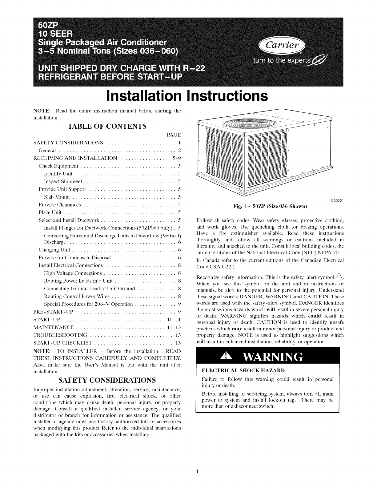
Fig. 1 - 50ZP (Size 036 Shown)
Follow all safety codes. Wear safety glasses, protective clothing,
and work gloves. Use quenching cloth for brazing operations.
Have a fire extinguisher available. Read these instructions
thoroughly and follow all warnings or cautions included in
literature and attached to the unit. Consult local building codes, the
current editions of the National Electrical Code (NEC) NFPA 70.
In Canada refer to the current editions of the Canadian Electrical
Code CSA C22.1.
Recognize safety information. This is the safety-alert symbol /_.
When you see this symbol on the unit and in instructions or
manuals, be alert to the potential for personal injury. Understand
these signal words; DANGER, WARNING, and CAUTION. These
words are used with the safety-alert symbol. DANGER identifies
the most serious hazards which will result in severe personal injury
or death. WARNING signifies hazards which could result in
personal injury or death. CAUTION is used to identify unsafe
practices which may result in minor personal injury or product and
property damage. NOTE is used to highlight suggestions which
will result in enhanced installation, reliability, or operation.
ELECTRICAL SHOCK HAZARD
Failure to follow this warning could result in personal
injury or death.
Before installing or servicing system, always turn off main
power to system and install lockout tag. There may be
more than one disconnect switch.
11.57
[294.0]
16.06
[408.0]
9.75
COND
COl L_\\
m
NEe, REQUIRED CLEARANCES,
BETWEEN UNITS, POWER ENTRY SIDE .................................... 42.00 [1066.8]
UNiT AND UNGROUNDED SURFACES, POWER ENTRY SIDE .36.00 [914.0]
UNIT AND BLOCK OR CONCRETE WALLS AND OTHER
t
\
\
\
14.0 DIA.
[356.0]
DUCT OPENINGS
i
EVAP COIL_ \
REAR VIEW
50.98
[1295.0]
BOTTOM Of UNIT
\
\
GROUNDED SURFACES, POWER ENTRY SIDE ......................... 42.00 [1066.8]
REQUIRED CLEARANCE FOR OPERATION AND SERVICING
CONDENSER COiL ACCESS SiDE .............................................. 30_00 [762.0]
POWER ENTRY SIDE .................................................................... 30.00 [762.0]
(EXCEPT FOR NEC REQUIREMENTS)
UNIT TOP ....................................................................................... 48.00 [1219.2]
SIDE OPPOSITE DUCTS .............................................................. 30.00 [762.0]
LEGEND
NEC National Electrical Code
NOTES:
1. Clearances must be maintained to prevent recirculation of air from outdooh
fan discharge, with the exception of the condenser coil (30.00 in [914.0 mini. A
removable fence or barricade requires no clearance.
2. Dimensions are in inches. Dimensions in [] are in millimeters.
INCHES [mm]
iNCHES [ram]
\
o
31.99
[812.5]
BOTTOM OF UNIT
t
LEFT SIDE VIEW
UNIT
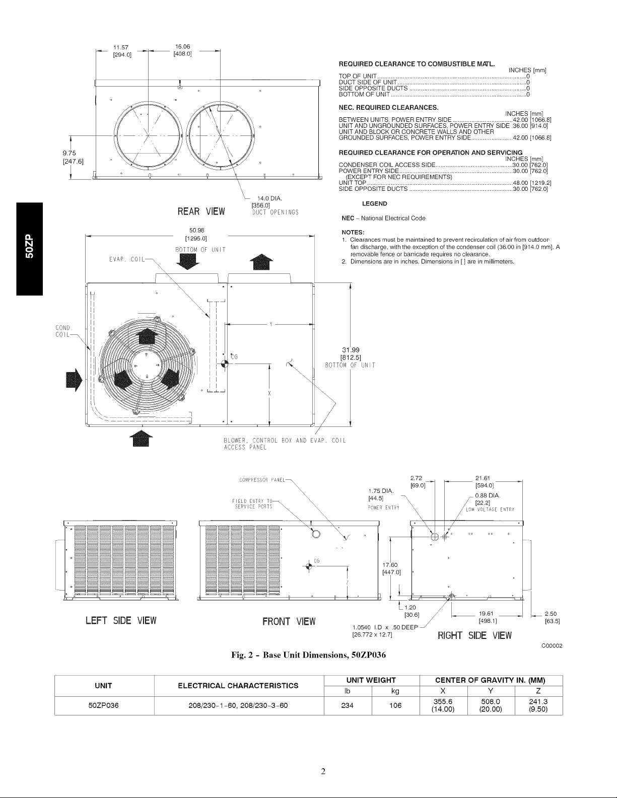
50ZP036
BLOWER, CONTROL BOX AND EVAP COIL
ACCESS PANEL
C('WIRESSCR FANEL_\
SERdlCE PORTS
FRONT VIEW
Fig. 2 - Base Unit Dimensions, 50ZP036
ELECTRICAL CHARACTERISTICS
208/230-1-60, 208/230-3-60
/
2.72 21.61
\\\\\\
\
[44.5]
1.75 DIA. [69.0]_ [594.0]
/
17.60
Z
UNIT WEIGHT
Ib kg
234 106
[447.0
1.2o/L
[30.6] 19.01
1.0540 t.D x .50 DEEP S
[26.772x12.7] RIGHT SIDE VIEW
/ [498.1]
CENTER OF GRAVITY IN. (MM)
X Y Z
355.6 508.0 241.3
(14.00) (20.00) (9.50)
2,50
[63.5]
C00002
9.75
11.57 16.06
[294.0] [408.0]
REAR VIEW
EVAPORATOR
COIL
\
\L 14.0 DIA.
[356.0]
DUCT OPENINGS
50.98
[1295.0]
BOTTOM OF UNIT
\\\
\, 77
I
I
REQUIRED CLEARANCE TO COMBUSTIBLE M/£-L.
TOP OF UNIT ......................................................................................... 0
DUCT SIDE OF UNIT ............................................................................. 0
SIDE OPPOSITE DUCTS ...................................................................... 0
BOTTOM OF UNIT ................................................................................. 0
NEC. REQUIRED CLEARANCES.
BETWEEN UNITS, POWER ENTRY SIDE .................................... 42.00 [1066.8]
UNIT AND UNGROUNDED SURFACES, POWER ENTRY SIDE .36.00 [914.0]
UNIT AND BLOCK OR CONCRETE WALLS AND OTHER
GROUNDED SURFACES, POWER ENTRY SIDE ......................... 42.00 [1066.8]
REQUIRED CLEARANCE FOR OPERATION AND SERVICING
CONDENSER COIL ACCESS SIDE .............................................. 30,00 [782.0]
POWER ENTRY SIDE .................................................................... 30,00 [782.0]
(EXCEPT FOR NEC REQUIREMENTS)
UNIT TOP ....................................................................................... 48.00 [1219.2]
SIDE OPPOSITE DUCTS .............................................................. 30,00 [762,0]
LEGEND
NEC National Electrical Code
NOTES:
1. Clearances must be maintained to prevent recircutation of air from outdoor-
fan discharge, with the exception of the condenser coil (36.00 in [914.0 mm]. A
removable fence or barricade requires no clearance.
2. Dimensions are in inches. Dimensions in [] are in millimeters.
INCHES [mm]
INCHES [mm]
INCHES [mm]
t
_9
[812.5]
BOTTOMOF UNIT
LEFT SIDEVIEW
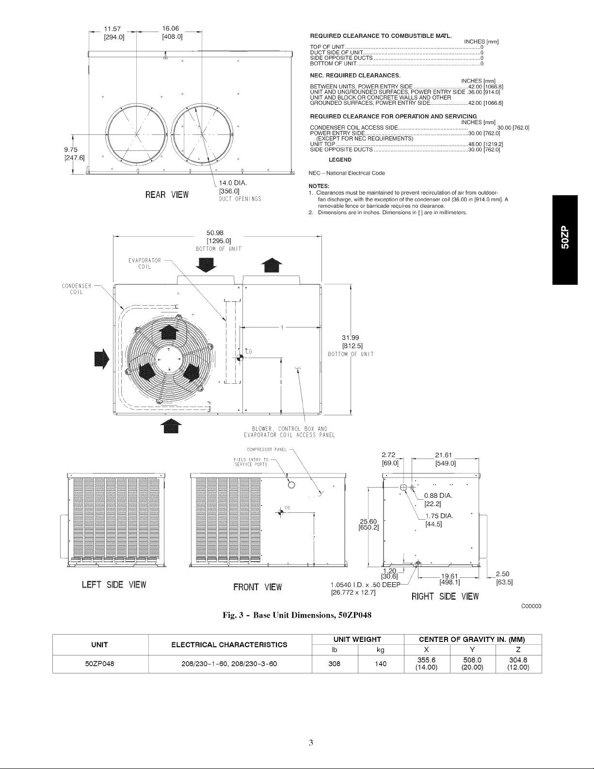
UNIT
50ZP048
I
o _
BLOWER, CONTROL BOX AND
EVAPORATOR COIL ACCESS PANEL
CC.'qPRESSORPA EL _\\
SERVICE PO_TS
FIELD E_T_f TC¸
FRONT VIEW
Fig. 3 - Base Unit Dimensions, 50ZP048
ELECTRICAL CHARACTERISTICS
208/230-1-60, 208/230-3-60
X
/ "
2.72
21.61
[549.0]
° \ , 088DIA.
[22.2]
25160
Z
[650.2]
X_1.75 DIA.
[44.51
_ LJ
1.0540 I.D. x .50 DEEP_
[30.6]
[26.772 x 12.7]
UNIT WEIGHT
Ib kg
308 140
RIGHTSIDEVIEW
19.61 2.50
[498.1] [63.5]
C00003
CENTER OF GRAVITY IN. (MM)
X Y Z
355.6 508.0 304.8
(14.00) (20.00) (12.00)
DIMENSIONS IN []ARE IN mm
4.63
[117.6]
18.88 _ 0
[352"5] ii ]
5.44
[138.3]
13.89
[352.8]
13.89
[352.7]
211
[53.7]
° i
i
REAR ViEW
50.98
1
3.50
[88.9]
REQUIRED CLEARANCE TO COMBUSTIBLE M/_L.
TOP OF UNIT .................................................................................. 0
DUCT SIDE OF UNIT ............................................................................. 0
SIDE OPPOSITE DUCTS ...................................................................... 0
BOTTOM OF UNIT ................................................................................. 0
NEC. REQUIRED CLEARANCES.
BETWEEN UNITS, POWER ENTRY SIDE .................................... 42.00 [1066.8]
UNIT AND UNGROUNDED SURFACES, POWER ENTRY SIDE .36.00 [914.0]
UNIT AND BLOCK OR CONCRETE WALLS AND OTHER
GROUNDED SURFACES, POWER ENTRY StDE ......................... 42.00 [1066.8]
27!80
REQUIRED CLEARANCE FOR OPERATION AND SERVICING
[706.0]
CONDENSER COIL ACCESS SiDE .............................................. 30.00 [762.0]
POWER ENTRY StDE .................................................................... 30.00 [762.0]
(EXCEPT FOR NEC REQUIREMENTS)
UNtTTOP ....................................................................................... 48.00 [1219.2]
SIDE OPPOSITE DUCTS .............................................................. 30.00 [762.0]
LEGEND
NEC National Electrical Code
NOTES:
1. Clearances must be maintained to prevent recirculation of air from outdoor-
fan discharge with the exception of the condenser coil (36.00 in [914.0 mm]. A
removable fence or barricade requires no clearance.
2. Dimensions are in inches. Dimensions in [] are in millimeters.
iNCHES [ram]
INCHES [mm]
iNCHES [mm]
t
Col,
C01L_
31 99
[812.5]
OTTO, OF JI,IT
i
CO[,TROL BOX ,:ND E,AP COIL
:,CC ESS PA_\EL
2.72 21.61
CoMPr_ESSQR PANEL \
F I ELO_,,_T 'f TO
t
2960
[751.8]
LEFT SIDE ViEW
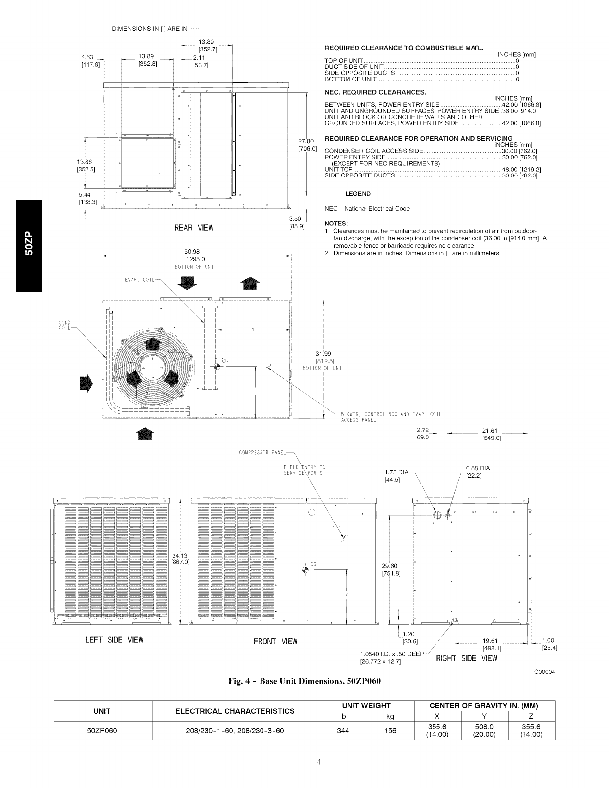
UNIT
50ZP060
FRONT VIEW
Fig. 4 - Base Unit Dimensions, 50ZP060
ELECTRICAL CHARACTERISTICS
208/230-1-60, 208/230-3-60
1.0540 I.D. x .50 DEEP ......
[26.772 x 12.7]
UNIT WEIGHT
Ib kg
344 156
i'
.2O
[3o.6]
...........................19.61...........................
/ [498.1 ] [25.4]
RIGHT SIDE VIEW
000004
CENTER OF GRAVITY IN. (MM)
X Y Z
355.6 508.0 355.6
(14.00) (20.00) (14.00)
CUT HAZARD
Failure to follow this caution may result in personal injury.
Sheet metal parts may have sharp edges or burrs. Use care
and wear appropriate clothing.
These instructions cover minimum requirements and conform to
existing national standards and safety codes. In some instances,
these instructions exceed certain local codes and ordinances,
especially those that may not have kept up with changing
residential construction practices. We require these instructions as a
minimum for a safe installation.
GENERAL -- 50ZP cooling units are fully self-contained and
designed for outdoor installation. See Fig. 1. As shown in Fig. 2-4,
units are shipped in a horizontal-discharge configuration for
installation on a ground-level slab. All units can be
field-converted to downflow discharge configurations for rooftop
applications with a field-supplied plenum
RECEIVING AND INSTALLATION
Step 1 -- Check Equipment
IDENTIFY UNIT -- The unit model number and serial number
are stamped on the unit identification plate. Check this information
against shipping papers.
INSPECT SHIPMENT -- Inspect for shipping damage while unit
is still on shipping pallet. If unit appears to be damaged or is torn
loose from its securing points, have it examined by transportation
inspectors before removal. Forward claim papers directly to
transportation company. Manufacturer is not responsible for any
damage incurred in transit.
Check all items against shipping list. Immediately notify the
nearest Carrier Air Conditioning office if any item is missing.
To prevent loss or damage, leave all parts in original packages until
installation.
Step 2 -- Provide Unit Support
SLAB MOUNT -- Place the unit on a rigid, level surface, suitable
to support the unit weight. The flat surface should extend
approximately 2-in. (51 mm) beyond the unit casing on the 2
sides. The duct connection side and condensate drain connection
sides should be flush with the edge of the flat surface. A concrete
pad or a suitable fiberglass mounting pad is recommended.
A 6-in. (152 mm) wide gravel apron should be used around the
flat surface to prevent airflow blockage by grass or shrubs. Do not
secure the unit to the flat surface except where required by local
codes.
The unit should be level to within 1/4 in. (6 mm). This is necessary
for the unit drain to function properly,
Step 3 -- Provide Clearances
The required minimum service clearances and clearances to
combustibles are shown in Fig. 2-4. Adequate ventilation and
condenser air must be provided.
The condenser fan pulls air through the condenser coil and
discharges it through the fan on the top cover. Be sure that the fan
discharge does not recirculate to the condenser coil. Do not locate
the unit in either a corner or under an overhead obstruction. The
minimum clearance under a partial overhang (such as a normal
house overhang) is 48 in. (1219 mm) above the unit top. The
maximum horizontal extension of a partial overhang must not
exceed 48 in. (1219 mm).
Do not place the unit where water, ice, or snow from an overhang
or roof will damage or flood the unit. The unit may be installed on
wood flooring or on Class A, B, or C roof covering materials.
Step 4 -- Place Unit
Unit can be moved with the handholds provided in the unit
basepan. Refer to Table 1 for operating weights. Use extreme
caution to prevent damage when moving the unit. Unit must
remain in an upright position during all moving operations. The
unit must be level for proper condensate drainage; the
ground-level pad must be level before setting the unit in place.
When a field-fabricated support is used, be sure that the support is
level and that it properly supports the unit.
Step 5 -- Select and Install Ductwork
The design and installation of the duct system must be in
accordance with:
• the standards of the NFPA (National Fire Protection Association)
for installation of nonresidence-type air conditioning and
ventilating systems;
• NFPA90A or residence-type, NFPA90B; and/or local codes and
residence-type, NFPA 90B;
• and/or local codes and ordinances.
Select and size ductwork, supply-air registers and return-air grilles
according to ASHRAE (American Society of Heating,
Refrigeration, and Air Conditioning Engineers) recommendations.
Use the duct flanges provided on the supply- and return-air
openings on the side of the unit. See Fig. 2-4 for connection sizes
and locations. The 14-in. (356 mm) round duct collars (size
036-048 units) are shipped inside the unit attached to the indoor
blower. They are field-installed and must be removed from the
indoor cavity prior to start-up, even if they are not used for
installation.
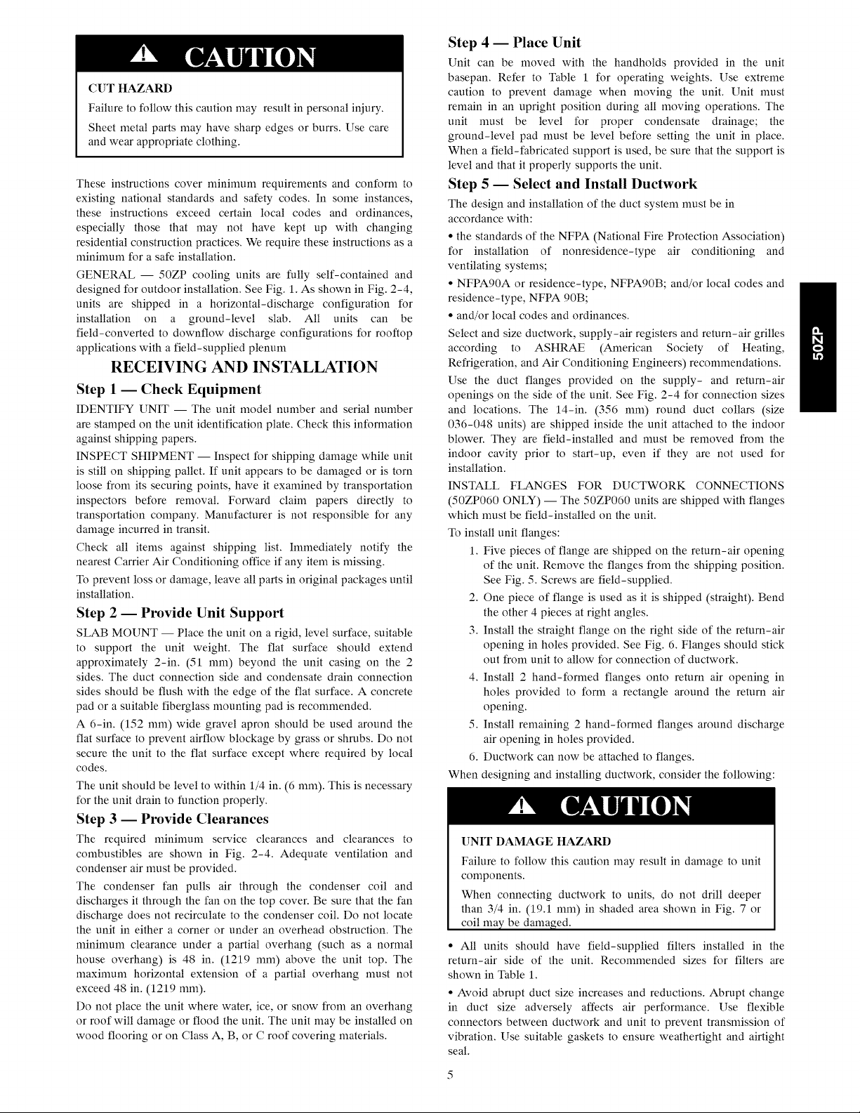
INSTALL FLANGES FOR DUCTWORK CONNECTIONS
(50ZP060 ONLY) -- The 50ZP060 units are shipped with flanges
which must be field-installed on the unit.
To install unit flanges:
1. Five pieces of flange are shipped on the return-air opening
of the unit. Remove the flanges from the shipping position.
See Fig. 5. Screws are field-supplied.
2. One piece of flange is used as it is shipped (straight). Bend
the other 4 pieces at right angles.
3. Install the straight flange on the right side of the return-air
opening in holes provided. See Fig. 6. Flanges should stick
out from unit to allow for connection of ductwork.
4. Install 2 hand-formed flanges onto return air opening in
holes provided to form a rectangle around the return air
opening.
5. Install remaining 2 hand-formed flanges around discharge
air opening in holes provided.
6. Ductwork can now be attached to flanges.
When designing and installing ductwork, consider the following:
[]NIT DAMAGE HAZARD
Failure to follow this caution may result in damage to unit
components.
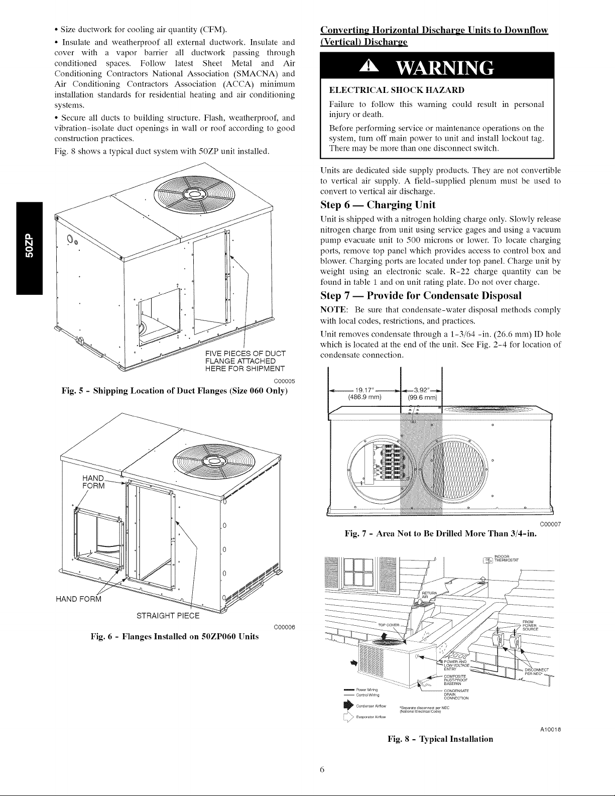
When connecting ductwork to units, do not drill deeper
than 3/4 in. (19.1 mm) in shaded area shown in Fig. 7 or
coil ma}zbe damaged.
• All units should have field-supplied filters installed in the
return-air side of the unit. Recommended sizes for filters are
shown in Table 1.
• Avoid abrupt duct size increases and reductions. Abrupt change
in duct size adversely affects air performance. Use flexible
connectors between ductwork and unit to prevent transmission of
vibration. Use suitable gaskets to ensure weathertight and airtight
seal.
• Size ductwork for cooling air quantity (CFM).
• Insulate and weatherproof all external ductwork. Insulate and
cover with a vapor barrier all ductwork passing through
conditioned spaces. Follow latest Sheet Metal and Air
Conditioning Contractors National Association (SMACNA) and
Air Conditioning Contractors Association (ACCA) minimum
installation standards for residential heating and air conditioning
systems.
• Secure all ducts to building structure. Flash, weatherproof, and
vibration-isolate duct openings in wall or roof according to good
construction practices.
Fig. 8 shows a typical duct system with 50ZP unit installed.
FIVE PIECES OF DUCT
FLANGE ATTACHED
HERE FOR SHIPMENT
C00005
Fig. 5 - Shipping Location of Duct Flanges (Size 060 Only)
Converting Horizontal Discharge Units to Downflow
(Vertical) Discharge
ELECTRICALSHOCK HAZARD
Failure to follow this warning could result in personal
injury or death.
Before performing service or maintenance operations on the
system, turn off main power to unit and install lockout tag.
There may be more than one disconnect switch.
Units are dedicated side supply )roducts. They are not convertible
to vertical air supply. A field-supplied plenum must be used to
convert to vertical air discharge.
Step 6 -- Charging Unit
Unit is shipped with a nitrogen holding charge only. Slowly release
nitrogen charge from unit using service gages and using a vacuum
pump evacuate unit to 500 microns or lower. To locate charging
ports, remove top panel which provides access to control box and
blower. Charging ports are located under top panel. Charge unit by
weight using an electronic scale. R-22 charge quantity can be
found in table 1 and on unit rating plate. Do not over charge.
Step 7 -- Provide for Condensate Disposal
NOTE: Be sure that condensate-water disposal methods comply
with local codes, restrictions, and practices.
Unit removes condensate through a 1-3/64 -in. (26.6 mm) ID hole
which is located at the end of the unit. See Fig. 2-4 for location of
condensate connection.
HAND FORM
Fig. 6 - Flanges Installed on 50ZP060 Units
STRAIGHT PIECE
C00006
Fig. 7 - Area Not to Be Drilled More Than 3/4-in.
Power Wiring
-- Control Wiring
Condenser Airflow
*Separate disconnect per NEC
(National El_trioal Code)
Fig. 8 - Typical Installation
FROM
POWER ......
SOURCE
DISCONNECT
PER NEC*.
C00007
A10018
 Loading...