


50TFQ008-012 Single-Package Rooftop Heat Pump Units
Installation, Start-Up and
Service Instructions
CONTENTS
Page
SAFETY CONSIDERATIONS . . . . . . . . . . . . . . . . . . . . . . . . .1
INSTALLATION . . . . . . . . . . . . . . . . . . . . . . . . . . . . . . . . . . . 1-43
Step 1— Provide Unit Support. . . . . . . . . . . . . . . . . . . . . . .1
•ROOF CURB
•SLAB MOUNT
•ALTERNATE UNIT SUPPORT
Step 2 — Field Fabricate Ductwork . . . . . . . . . . . . . . . . . . |
3 |
|
Step 3 |
— Install Condensate Drain Line |
|
and External Trap . . . . . . . . . . . . . . . . . . . . . . . . . . . . . . . . . |
3 |
|
Step 4 |
— Rig and Place Unit. . . . . . . . . . . . . . . . . . . . . . . . . |
3 |
• POSITIONING |
|
|
Step 5 |
— Make Electrical Connections . . . . . . . . . . . . . . |
7 |
•FIELD POWER SUPPLY
•FIELD CONTROL WIRING
•DEFROST BOARD
•HEAT ANTICIPATOR SETTINGS
Step 6 — Adjust Factory-Installed Options . . . . . . . . .12
•DISCONNECT SWITCH
•CONVENIENCE OUTLET
•NOVAR CONTROLS
•MANUAL OUTDOOR-AIR DAMPER
•PREMIERLINK™ CONTROL
•OPTIONAL ECONOMI$ER IV AND ECONOMI$ER2
•ECONOMI$ER IV STANDARD SENSORS
•ECONOMI$ER IV CONTROL MODES
Step 7 — Adjust Indoor-Fan Speed . . . . . . . . . . . . . . . . .25
PRE-START-UP . . . . . . . . . . . . . . . . . . . . . . . . . . . . . . . . . . . . .44 START-UP . . . . . . . . . . . . . . . . . . . . . . . . . . . . . . . . . . . . . . . 44-47 SERVICE . . . . . . . . . . . . . . . . . . . . . . . . . . . . . . . . . . . . . . . . 47-49 TROUBLESHOOTING . . . . . . . . . . . . . . . . . . . . . . . . . . . . 49-53 INDEX . . . . . . . . . . . . . . . . . . . . . . . . . . . . . . . . . . . . . . . . . . . . . .54 START-UP CHECKLIST . . . . . . . . . . . . . . . . . . . . . . . . . . CL-1
SAFETY CONSIDERATIONS
Installation and servicing of air-conditioning equipment can be hazardous due to system pressure and electrical components. Only trained and qualified service personnel should install, repair, or service air-conditioning equipment.
Untrained personnel can perform basic maintenance functions of cleaning coils and filters and replacing filters. All other operations should be performed by trained service personnel. When working on air-conditioning equipment, observe precautions in the literature, tags and labels attached to the unit, and other safety precautions that may apply.
Follow all safety codes. Wear safety glasses and work gloves. Use quenching cloth for unbrazing operations. Have fire extinguisher available for all brazing operations.
Before performing service or maintenance operations on unit, turn off main power switch to unit and install lockout tag. Ensure voltage listed on unit data plate agrees with electrical supply provided for the unit. Electrical shock could cause personal injury.
INSTALLATION
Unit is shipped in the vertical configuration. To convert to horizontal configuration, remove side duct opening covers. Using the same screws, install covers on vertical duct openings with the insulation-side down. Seals around duct openings must be tight.
Step 1 — Provide Unit Support
ROOF CURB — Assemble and install the accessory roof curb in accordance with instructions shipped with the curb. See Fig. 1. Install insulation, cant strips, roofing felt, and counter flashing as shown. Ductwork must be attached to curb. If electric or control power will be routed through the basepan, use the proper accessory kit listed in Fig. 1, available from your local distributor. Attach the accessory thru-the-bottom service connections to the basepan in accordance with the accessory installation instructions. Connections must be installed before the unit is set on the roof curb.
IMPORTANT: The gasketing of the unit to the roof curb is critical for a water-tight seal. Install gasket supplied with the roof curb as shown in Fig. 1. Improperly applied gasket can also result in air leaks and poor unit performance.
The roof curb should be level. Unit leveling tolerances are shown in Fig. 2. This is necessary for the unit drain to function properly. Refer to Accessory Roof Curb Installation Instructions for additional information as required.
Manufacturer reserves the right to discontinue, or change at any time, specifications or designs without notice and without incurring obligations.
Book |
1 |
4 |
Catalog No. 04-53500019-01 |
Printed in U.S.A. |
Form 50TFQ-9SI |
Pg 1 |
9-05 |
Replaces: 50TFQ-7SI |
Tab |
5a |
5a |
|
|
|
|
|
|
|
|
|
|
|
|
|
|
|

Fig. 1 — Roof Curb Details
2

MAXIMUM ALLOWABLE
DIFFERENCE (in.)
A-B |
B-C |
A-C |
0.5 |
1.0 |
1.0 |
Fig. 2 — Unit Leveling Tolerances
SLAB MOUNT (Horizontal Units Only) — Provide a level concrete slab that extends a minimum of 6 in. beyond the unit cabinet on all sides. Install a gravel apron in front of the outdoor coil air inlet to prevent grass and foliage from obstructing airflow.
NOTE: Horizontal units may be installed on a roof curb if required.
ALTERNATE UNIT SUPPORT — When the curb or adapter cannot be used, support unit with sleeper rails using unit curb or adapter support area. If sleeper rails cannot be used, support the long sides of the unit with a minimum of 3 equally spaced 4-in. x 4-in. pads on each side.
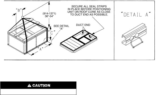
Step 2 — Field Fabricate Ductwork — On vertical discharge units, secure all ducts to the roof curb and building structure. Do not connect ductwork to the unit. For horizontal applications, field-supplied flanges should be attached to horizontal discharge openings and all ductwork attached to the flanges. Insulate and weatherproof all external ductwork, joints, and roof openings with counter flashing and mastic in accordance with applicable codes.
Ducts passing through an unconditioned space must be insulated and covered with a vapor barrier.
If a plenum return is used on a vertical unit, the return should be ducted through the roof deck to comply with applicable fire codes.
A minimum clearance is not required around ductwork. Cabinet return-air static pressure (a negative condition) should not exceed 0.35 in. wg with economizer, or 0.45 in. wg without economizer.
Step 3 — Install Condensate Drain Line and External Trap — Condensate drain connections are located at the bottom and end of the unit. Unit discharge connections do not determine the use of drain connections; either drain connection can be used in vertical or horizontal applications.
When using the standard end drain connection, make sure the plug in the alternate bottom connection is tight before installing the unit.
To use the bottom drain connection for a roof curb installation, relocate the factory-installed plug from the bottom connection to the end connection. The center drain plug looks like a star connection, but can be removed with a 1/2-in. socket drive extension. See Fig. 3. The piping for the condensate drain and external trap can be completed after the unit is in place.
All units must have an external trap for condensate drainage. Install a trap at least 4-in. deep and protect against freezeup. If drain line is installed downstream from the external trap,
pitch the line away from the unit at 1/4-in. per ft of run. Do not use a pipe size smaller than the unit connection. See Fig. 4.
Step 4 — Rig and Place Unit — Inspect the unit for transportation damage. File any claim with the transportation agency. Keep the unit upright and do not drop it. Spreader bars are not required if top crating is left on the unit. Rollers may be used to move the unit across a roof. Level by using the unit frame as a reference. See Table 1 and Fig. 5 for additional information. Operating weight is shown in Table 1 and Fig. 5.
Lifting holes are provided in the base rails as shown in Fig. 5 and 6. Refer to rigging instructions on the unit.
POSITIONING — Maintain clearance around and above the unit to provide proper airflow and service access. See Fig. 6.
Position the unit on the roof curb so that the following clearances are maintained: 1/4-in. clearance between the roof curb and base rails on each side and in front of the unit; 35/16-in. clearance between the roof curb and the outdoor fan end of the unit (see Fig. 1, section C-C).
Do not install the unit indoors. Do not locate the unit air inlet near exhaust vents or other sources of contaminated air.
Although the unit is weatherproof, guard against water from higher level runoff and overhangs.
After the unit is in position, remove the polyethylene shipping wrapper and rigging skid.
HORIZONTAL |
DRAIN PLUG |
DRAIN OUTLET |
|
NOTE: Drain plug is shown in factory-installed position.
Fig. 3 — Condensate Drain Pan (Side View)
NOTE: Trap should be deep enough to offset maximum unit static difference. A 4-in. trap is recommended.
Fig. 4 — Condensate Drain Piping Details
3
NOTES:
1. Dimension in ( ) is in millimeters.
2.Hook rigging shackles through holes in base rail, as shown in detail “A.” Holes in base rails are centered around the unit center of gravity. Use wooden top skid when rigging to prevent rigging straps from damaging unit.
3.Unit weights do not include economizer. See Table 1 for economizer weights.
All panels must be in place when rigging. Unit is not designed for handling by a fork truck. Damage to unit may result.
50TFQ |
WEIGHT |
|
A |
|
B |
|
C |
||
Lb |
Kg |
in. |
mm |
in. |
mm |
in. |
|
mm |
|
|
|
||||||||
008 |
940 |
426 |
77.42 |
1966.5 |
41.5 |
1054 |
42.12 |
|
1070 |
009 |
965 |
438 |
77.42 |
1966.5 |
41.5 |
1054 |
42.12 |
|
1070 |
012 |
1015 |
460 |
77.42 |
1966.5 |
41.5 |
1054 |
42.12 |
|
1070 |
Fig. 5 — Rigging Details
4
Table 1 — Physical Data
UNIT SIZE 50TFQ |
|
008 |
|
|
009 |
|
|
012 |
|
NOMINAL CAPACITY (tons) |
|
71/2 |
|
|
81/2 |
|
|
10 |
|
OPERATING WEIGHT (lb) |
|
|
|
|
|
|
|
|
|
Unit |
|
940 |
|
|
965 |
|
|
1015 |
|
Economizer |
|
|
|
|
|
|
|
|
|
EconoMi$er IV |
|
75 |
|
|
75 |
|
|
75 |
|
Roof Curb* |
|
143 |
|
|
143 |
|
|
143 |
|
COMPRESSOR (Hermetic) |
|
|
Reciprocating |
|
|
Scroll |
|||
Quantity |
|
2 |
|
|
2 |
|
|
2 |
|
|
|
||||||||
Oil (oz) |
|
45 ea |
|
|
54 ea |
|
|
54 ea |
|
REFRIGERANT TYPE |
|
|
|
|
R-22 |
|
|
|
|
Operating Charge (lb-oz) |
|
|
|
|
|
|
|
|
|
Circuit 1 |
|
5-14 |
|
|
8- 6 |
|
|
7-14 |
|
|
|
|
|||||||
Circuit 2 |
|
5-13 |
|
|
8-13 |
|
|
8- 3 |
|
OUTDOOR COIL |
|
Enhanced Copper Tubes, Aluminum Lanced Fins, Acutrol™ Feed Device |
|||||||
Rows...Fins/in. |
|
1...17 |
|
|
2...17 |
|
|
2...17 |
|
|
|
|
|||||||
Total Face Area (sq ft) |
|
20.50 |
|
|
18.00 |
|
|
18.30 |
|
OUTDOOR FAN |
|
|
|
|
Propeller Type |
|
|
|
|
Nominal Cfm |
|
6500 |
|
|
6500 |
|
|
6500 |
|
|
|
|
|||||||
Quantity...Diameter (in.) |
|
2...22 |
|
|
2...22 |
|
|
2...22 |
|
Motor Hp...Rpm |
|
1/4...1100 |
|
|
1/4...1100 |
|
|
1/4...1100 |
|
Watts Input (Total) |
|
500 |
|
|
500 |
|
|
500 |
|
INDOOR COIL |
|
Enhanced Copper Tubes, Aluminum Double-Wavy Fins, Acutrol Feed Device |
|||||||
Rows...Fins/in. |
|
3...15 |
|
|
3...15 |
|
|
3...15 |
|
|
|
|
|||||||
Total Face Area (sq ft) |
|
8.0 |
|
|
8.0 |
|
|
11.1 |
|
INDOOR FAN |
|
|
|
|
Centrifugal Type |
|
|
|
|
Quantity...Size (in.) |
Std |
1...15 x 15 |
|
|
1...15 x 15 |
|
|
1...15 x 15 |
|
|
|
|
|||||||
|
Alt |
1...15 x 15 |
|
|
— |
|
|
1...15 x 15 |
|
|
High-Static |
1...15 x 15 |
|
|
1...15 x 15 |
|
|
1...15 x 15 |
|
Type Drive |
Std |
Belt |
|
|
Belt |
|
|
Belt |
|
|
Alt |
Belt |
|
|
— |
|
|
Belt |
|
Nominal Cfm |
High-Static |
Belt |
|
|
Belt |
|
|
Belt |
|
|
3000 |
|
|
3600 |
|
|
4000 |
||
Maximum Continuous Bhp |
Std |
2.40 |
|
|
2.40 |
|
|
2.40 |
|
|
Alt |
2.40 |
|
|
— |
|
2.90 |
||
|
High-Static |
3.70 |
|
|
3.70 |
|
|
5.25 |
|
Motor Frame Size |
Std |
56 |
|
|
56 |
|
|
56 |
|
|
Alt |
56 |
|
|
— |
|
56 |
||
|
High-Static |
56 |
|
|
56 |
|
|
56 |
|
Nominal Rpm |
Std |
— |
|
|
— |
|
|
— |
|
|
Alt |
— |
|
|
— |
|
|
— |
|
|
High-Static |
1725 |
|
|
1725 |
|
|
1725 |
|
Fan Rpm Range |
Std |
590840 |
|
|
685935 |
|
|
685935 |
|
|
Alt |
685935 |
|
|
— |
|
835-1085 |
||
Motor Bearing Type |
High-Static |
860-1080 |
|
|
860-1080 |
|
|
830-1130 |
|
|
Ball |
|
|
Ball |
|
|
Ball |
||
Maximum Allowable Rpm |
|
2100 |
|
|
2100 |
|
|
2100 |
|
Motor Pulley Pitch Diameter Min/Max (in.) |
Std |
2.4/3.4 |
|
|
2.8/3.8 |
|
|
2.8/3.8 |
|
|
Alt |
2.8/3.8 |
|
|
— |
|
3.4/4.4 |
||
|
High-Static |
4.0/5.0 |
|
|
4.0/5.0 |
|
|
2.8/3.8 |
|
Nominal Motor Shaft Diameter (in.) |
Std |
5/8 |
|
|
5/8 |
|
|
5/8 |
|
|
Alt |
5/8 |
|
|
— |
|
7/8 |
||
Fan Pulley Pitch Diameter (in.) |
High-Static |
7/8 |
|
|
7/8 |
|
|
7/8 |
|
Std |
7.0 |
|
|
7.0 |
|
|
7.0 |
||
|
Alt |
7.0 |
|
|
— |
|
7.0 |
||
|
High-Static |
8.0 |
|
|
8.0 |
|
|
5.8 |
|
Belt, Quantity...Type...Length (in.) |
Std |
1...A...53 |
|
|
1...A...48 |
|
|
1...A...49 |
|
|
Alt |
1...A...49 |
|
|
— |
|
|
1...A...51 |
|
|
High-Static |
1...A...65 |
|
|
1...A...53 |
|
|
1...BX...48 |
|
Pulley Center Line Distance (in.) |
Std |
16.75-19.25 |
|
|
16.75-19.25 |
|
|
15.85-17.50 |
|
|
Alt |
16.75-19.25 |
|
|
— |
|
15.85-17.50 |
||
|
High-Static |
16.75-19.25 |
|
|
16.75-19.25 |
|
|
15.85-17.50 |
|
Speed Change per Full Turn of |
Std |
50 |
|
|
50 |
|
|
50 |
|
Moveable Pulley Flange (rpm) |
Alt |
50 |
|
|
— |
|
50 |
||
|
High-Static |
60 |
|
|
60 |
|
|
60 |
|
Moveable Pulley Maximum Full Turns |
Std |
5 |
|
|
5 |
|
|
5 |
|
From Closed Position |
Alt |
5 |
|
|
— |
|
5 |
||
|
High-Static |
5 |
|
|
5 |
|
|
6 |
|
Factory Setting |
Std |
5 |
|
|
5 |
|
|
5 |
|
|
Alt |
5 |
|
|
— |
|
5 |
||
|
High-Static |
5 |
|
|
5 |
|
|
5 |
|
Factory Speed Setting (rpm) |
Std |
590 |
|
|
685 |
|
|
685 |
|
|
Alt |
685 |
|
|
— |
|
835 |
||
Fan Shaft Diameter at Pulley (in.) |
High-Static |
860 |
|
|
880 |
|
|
887 |
|
|
1 |
|
|
1 |
|
|
1 |
||
HIGH-PRESSURE SWITCH (psig) |
|
|
|
|
|
|
|
|
|
Standard Compressor Internal Relief (Differential) |
|
|
450 ± 50 |
|
|
|
|
||
Cutout |
|
|
428 |
|
|
|
|
||
Reset (Auto.) |
|
|
320 |
|
|
|
|
||
LOSS-OF-CHARGE (LOW-PRESSURE) SWITCH (psig) |
|
|
|
|
|
|
|
|
|
Cutout |
|
|
7 ± 3 |
|
|
|
|
||
Reset (Auto.) |
|
|
22 ± 5 |
|
|
|
|
||
FREEZE PROTECTION THERMOSTAT (F) |
|
|
|
|
|
|
|
|
|
Opens |
|
|
30 ± 5 |
|
|
|
|
||
Closes |
|
|
45 ± 5 |
|
|
|
|
||
OUTDOOR-AIR INLET SCREENS |
|
|
|
|
Cleanable. |
|
|
|
|
|
|
Screen quantity and size vary based on options selected. |
|||||||
RETURN-AIR FILTERS |
|
|
|
|
Throwaway |
|
|
|
|
Quantity...Size (in.) |
|
4...16 x 20 x 2 |
|
|
4...16 x 20 x 2 |
|
|
|
4...20 x 20 x 2 |
|
|
|
|
|
|
||||
LEGEND |
|
*Weight of 14-in. roof curb. |
|
|
|
||||
Bhp — Brake Horsepower |
|
|
|
|
|
|
|
|
|
5

6
Fig. 6 — Base Unit Dimensions

Step 5 — Make Electrical Connections
Unit cabinet must have an uninterrupted, unbroken electrical ground to minimize the possibility of personal injury if an electrical fault should occur. This ground may consist of electrical wire connected to unit ground lug in control compartment, or conduit approved for electrical ground when installed in accordance with NEC (National Electrical Code) ANSI (American National Standards Institute)/ NFPA (National Fire Protection Association) 70 latest year and local electrical codes. Failure to follow this warning could result in the installer being liable for personal injury of others.
FIELD POWER SUPPLY — All units except 208/230-v units are factory-wired for the voltage shown on the unit nameplate. If the 208/230-v unit is to be connected to a 208-v power supply, the transformer must be rewired by disconnecting the black wire from the 230-v 1/4-in. male spade terminal on the transformer and connecting it to the 208-v 1/4-in. male spade terminal from the transformer.
Refer to the unit label diagram for additional information. Pigtails are provided for field wire connections. Use factorysupplied splices or a UL (Underwriters’ Laboratories) approved copper/aluminum connector.
When installing units, provide a disconnect per the NEC.
All field wiring must comply with the NEC and local requirements. In Canada, electrical connections must be made in accordance with CSA (Canadian Standards Association) C22.1 Canadian Electrical Code Part One.
Install field wiring as follows:
1.Install conduit through the side panel openings. For units without electric heat, install conduit between the disconnect and control box.
2.Install power lines to terminal connections as shown in Fig. 7.
3.For units with electric heat, refer to Table 2 and Accessory Installation Instructions.
During operation, voltage to compressor terminals must be within range indicated on unit nameplate (see Tables 3A and 3B). On 3-phase units, voltages between phases must be balanced within 2%, and the current within 10%. Use the formula shown in Tables 3A and 3B, Note 2 on page 11 to determine the percentage of voltage imbalance. Operation on improper line voltage or excessive phase imbalance constitutes abuse and may cause damage to electrical components. Such operation would invalidate any applicable Carrier warranty.
208/230-3-60 |
|
575-3-60 |
460-3-60 |
|
|
|
|
LEGEND |
C |
— Contactor |
|
COMP — |
Compressor |
|
IFC |
— |
Indoor-Fan Contactor |
NEC |
— |
National Electrical Code |
TB |
— |
Terminal Block |
|
|
Field Wiring |
|
|
Factory Wiring |
|
|
Splice Connection |
|
|
(Factory-Supplied) |
Fig. 7 — Power Wiring Connections
7
Table 2 — Electric Heating Capacities
50TFQ |
UNIT VOLTAGE |
ACCESSORY |
ELECTRIC HEATER |
SINGLE POINT BOX |
||
PART NUMBER |
PACKAGE NO. |
|||||
UNIT SIZE |
(60 Hz) |
|
kW |
|||
|
CRHEATER---A00 |
CRSINGLE---A00 |
||||
|
|
|
|
|||
|
|
7.8/ |
9.6/10.4 |
017 |
007 |
|
|
208/230/240 |
12.0/14.7/16.0 |
010 |
007 |
||
|
18.6/22.8/24.8 |
011 |
009 |
|||
|
(3 phase) |
|||||
|
24.0/29.4/32.0 |
012 |
009 |
|||
|
|
|||||
|
|
31.8/39.0/42.4* |
012 and 017 |
013 |
||
008, 009 |
|
12.8/13.9 |
016 |
006 |
||
460/480 |
15.2/16.5 |
013 |
006 |
|||
|
||||||
|
25.6/27.8 |
014 |
008 |
|||
|
(3 phase) |
|||||
|
30.4/33.0 |
015 |
008 |
|||
|
|
|||||
|
|
38.4/41.7* |
014 and 016 |
010 |
||
|
575 |
|
17.0 |
018 |
006 |
|
|
(3 phase) |
|
34.0 |
019 |
006† |
|
|
|
7.8/ |
9.6/10.4 |
017 |
012 |
|
|
208/230/240 |
12.0/14.7/16.0 |
010 |
012 |
||
|
24.0/29.4/32.0 |
012 |
015 |
|||
|
(3 phase) |
|||||
|
31.8/39.0/42.4* |
012 and 017 |
017 |
|||
|
|
|||||
|
|
37.6/46.2/50.0* |
010 and 012 |
017 |
||
012 |
|
15.2/16.5 |
013 |
011 |
||
460/480 |
25.6/27.8 |
014 |
014 |
|||
|
30.4/33.0 |
015 |
014 |
|||
|
(3 phase) |
|||||
|
38.4/41.7* |
014 and 016 |
016 |
|||
|
|
|||||
|
|
45.9/50.0* |
013 and 015 |
016 |
||
|
575 |
|
17.0 |
018 |
011 |
|
|
|
34.0 |
019 |
014 |
||
|
(3 phase) |
|
||||
|
|
51.0* |
018 and 019 |
016 |
||
|
|
|
||||
*Two heater packages required to provide kW indicated.
†Use CRSINGLE008A00 for units with an electrical convenience outlet.
NOTES:
1.The rated heater voltage is 240, 480, and 575 v. If power distribution voltage varies from rated heater voltage, heater kW will vary accordingly.
2.To determine heater kW at voltages other than those shown in table, use the following formula:
Heater kW new = Heater kW rated x (unit power distribution voltage/rated heater voltage)2
As an example:
For a 16 kW heater rated at 240 v with a power distribution voltage of 215 v kW new = 16 kW (215/240)2
kW new = 12.8 kW (rating at 215 v)
Table 3A — Electrical Data (Units Without Electrical Convenience Outlet)
|
|
|
VOLTAGE |
COMPRESSOR |
|
|
ELECTRIC HEAT* |
POWER SUPPLY |
DISCONNECT |
|||||||||
50TFQ |
NOMINAL |
IFM |
RANGE |
(each) |
OFM |
IFM |
|
SIZE† |
||||||||||
|
|
|
|
|
|
|
|
|||||||||||
UNIT SIZE |
V-PH-Hz |
TYPE |
Min |
Max |
RLA |
LRA |
FLA |
FLA |
Nominal |
FLA |
MCA |
MOCP |
FLA |
LRA |
||||
|
|
|
|
|
kW** |
|||||||||||||
|
|
|
|
|
|
|
|
|
|
|
|
|
|
|
|
|
|
|
|
|
|
|
|
|
|
|
|
— |
— |
38.8/ 38.8 |
40/ 40†† |
41/ 41 |
229/229 |
||||
|
|
|
|
|
|
|
|
|
7.8/10.4 |
21.7/ 25.0 |
65.9/ |
70.0 |
70/ |
70 |
66/ |
69 |
251/254 |
|
|
|
STD |
187 |
254 |
13.4 |
91.0 |
1.4 |
5.8 |
12.0/16.0 |
33.3/ 38.5 |
80.4/ |
86.9 |
90/ |
90 |
79/ |
85 |
262/268*** |
|
|
|
18.6/24.8 |
51.6/ |
59.7 |
103.3/113.4 |
110/125 |
100/109 |
281/289*** |
||||||||||
|
|
|
|
|
|
|
|
|
||||||||||
|
|
|
|
|
|
|
|
|
24.0/32.0 |
66.6/ |
77.0 |
122.0/135.0 |
125/150 |
117/129 |
296/306*** |
|||
|
208/230-3-60 |
|
|
|
|
|
|
|
31.8/42.4 |
88.3/102.0 |
149.1/166.3 |
150/175 |
142/158 |
317/331*** |
||||
|
|
|
|
|
|
|
|
— |
— |
43.6/ 43.6 |
45/ 45†† |
46/ 46 |
273/273 |
|||||
|
|
|
|
|
|
|
|
|
||||||||||
|
|
|
|
|
|
|
|
|
7.8/10.4 |
21.7/ |
25.0 |
70.7/ |
74.8 |
80/ |
80 |
71/ |
75 |
294/298 |
|
|
HIGH-STATIC |
187 |
254 |
13.4 |
91.0 |
1.4 |
10.6 |
12.0/16.0 |
33.3/ |
38.5 |
85.2/ |
91.7 |
90/100 |
85/ |
91 |
306/311*** |
|
|
|
18.6/24.8 |
51.6/ |
59.7 |
108.1/118.2 |
110/125 |
106/115 |
324/332*** |
||||||||||
|
|
|
|
|
|
|
|
|
||||||||||
|
|
|
|
|
|
|
|
|
24.0/32.0 |
66.6/ |
77.0 |
126.8/139.8 |
150/150 |
123/135 |
339/350*** |
|||
|
|
|
|
|
|
|
|
|
31.8/42.4 |
88.3/102.0 |
153.9/171.1 |
175/175 |
148/164 |
361/375*** |
||||
|
|
|
|
|
|
|
|
|
— |
— |
19.1 |
20†† |
20 |
|
108 |
|||
|
|
|
|
|
|
|
|
|
13.9 |
16.7 |
40.0 |
40†† |
39 |
|
124 |
|||
008 |
|
STD |
414 |
508 |
6.7 |
42.0 |
0.7 |
2.6 |
16.5 |
19.8 |
43.8 |
45†† |
43 |
|
128 |
|||
(71/2 Tons) |
|
27.8 |
33.4 |
60.8 |
70 |
58 |
|
141 |
||||||||||
|
|
|
|
|
|
|
|
|
||||||||||
|
|
|
|
|
|
|
|
|
33.0 |
39.7 |
68.7 |
70 |
66 |
|
147 |
|||
|
460-3-60 |
|
|
|
|
|
|
|
41.7 |
50.2 |
81.8 |
90 |
78 |
|
158 |
|||
|
|
|
|
|
|
|
|
— |
— |
21.3 |
25†† |
23 |
|
130 |
||||
|
|
|
|
|
|
|
|
|
|
|||||||||
|
|
|
|
|
|
|
|
|
13.9 |
16.7 |
42.2 |
45†† |
42 |
|
146 |
|||
|
|
HIGH-STATIC |
414 |
508 |
6.7 |
42.0 |
0.7 |
4.8 |
16.5 |
19.8 |
46.0 |
50†† |
45 |
|
149 |
|||
|
|
27.8 |
33.4 |
63.0 |
70 |
61 |
|
163 |
||||||||||
|
|
|
|
|
|
|
|
|
|
|||||||||
|
|
|
|
|
|
|
|
|
33.0 |
39.7 |
70.9 |
80 |
68 |
|
169 |
|||
|
|
|
|
|
|
|
|
|
41.7 |
50.2 |
84.0 |
90 |
80 |
|
180*** |
|||
|
|
|
|
|
|
|
|
|
— |
— |
15.4 |
20†† |
16 |
|
97 |
|||
|
|
STD |
|
|
|
|
|
2.6 |
17.0 |
17.1 |
36.7 |
40†† |
36 |
|
114 |
|||
|
575-3-60 |
|
518 |
632 |
5.4 |
39.0 |
0.7 |
|
34.0 |
34.1 |
58.0 |
60†† |
55 |
|
131 |
|||
|
|
|
— |
— |
17.1 |
20†† |
18 |
|
114 |
|||||||||
|
|
|
|
|
|
|
|
|
|
|||||||||
|
|
HIGH-STATIC |
|
|
|
|
|
4.8 |
17.0 |
17.1 |
38.5 |
40†† |
38 |
|
132 |
|||
|
|
|
|
|
|
|
|
|
34.0 |
34.1 |
59.7 |
60†† |
57 |
|
149 |
|||
NOTE: Legend and Notes for Electrical Data are on page 11.
8
Table 3A — Electrical Data (Units Without Electrical Convenience Outlet) (cont)
|
|
|
VOLTAGE |
COMPRESSOR |
|
|
ELECTRIC HEAT* |
POWER SUPPLY |
|
DISCONNECT |
|||||||||
50TFQ |
NOMINAL |
IFM |
RANGE |
|
(each) |
OFM |
IFM |
|
|
SIZE† |
|||||||||
|
|
|
|
|
|
|
|
|
|
||||||||||
UNIT SIZE |
V-PH-Hz |
TYPE |
Min |
Max |
RLA |
|
LRA |
FLA |
FLA |
Nominal |
FLA |
MCA |
MOCP |
FLA |
LRA |
||||
|
|
|
|
|
|
kW** |
|||||||||||||
|
|
|
|
|
|
|
|
|
|
|
|
|
|
|
|
|
|
|
|
|
|
|
|
|
|
|
|
|
|
— |
— |
44.6/ 44.6 |
45/ 45†† |
47/ 47 |
321/321 |
||||
|
|
|
|
|
|
|
|
|
|
7.8/10.4 |
21.7/ |
25.0 |
71.7/ |
75.9 |
80/ |
80 |
72/ |
75 |
343/346 |
|
|
STD |
187 |
254 |
16.0 |
|
137.0 |
1.4 |
5.8 |
12.0/16.0 |
33.3/ |
38.5 |
86.2/ |
92.7 |
90/100 |
85/ |
91 |
354/360*** |
|
|
|
|
18.6/24.8 |
51.6/ |
59.7 |
109.1/119.2 |
110/125 |
106/115 |
373/381*** |
||||||||||
|
|
|
|
|
|
|
|
|
|
||||||||||
|
|
|
|
|
|
|
|
|
|
24.0/32.0 |
66.6/ |
77.0 |
127.9/140.9 |
150/150 |
123/135 |
388/398*** |
|||
|
208/230-3-60 |
|
|
|
|
|
|
|
|
31.8/42.4 |
88.3/102.0 |
155.0/172.1 |
175/175 |
148/164 |
409/428*** |
||||
|
|
|
|
|
|
|
|
|
— |
— |
49.4/ 49.4 |
50/ 50†† |
52/ 52 |
365/365 |
|||||
|
|
|
|
|
|
|
|
|
|
||||||||||
|
|
|
|
|
|
|
|
|
|
7.8/10.4 |
21.7/ |
25.0 |
76.5/ |
80.7 |
80/ |
90 |
77/ |
81 |
386/390*** |
|
|
HIGH-STATIC |
187 |
254 |
16.0 |
|
137.0 |
1.4 |
10.6 |
12.0/16.0 |
33.3/ |
38.5 |
91.0/ |
97.5 |
100/100 |
91/ |
96 |
398/403*** |
|
|
|
|
18.6/24.8 |
51.6/ |
59.7 |
113.9/124.0 |
125/125 |
112/121 |
416/424*** |
||||||||||
|
|
|
|
|
|
|
|
|
|
||||||||||
|
|
|
|
|
|
|
|
|
|
24.0/32.0 |
66.6/ |
77.0 |
132.7/145.7 |
150/150 |
129/141 |
431/442*** |
|||
|
|
|
|
|
|
|
|
|
|
31.8/42.4 |
88.3/102.0 |
159.8/176.9 |
175/200 |
154/170 |
453/467*** |
||||
|
|
|
|
|
|
|
|
|
|
— |
— |
22.7 |
25†† |
24 |
|
162 |
|||
|
|
|
|
|
|
|
|
|
|
13.9 |
16.7 |
43.6 |
45†† |
43 |
|
178 |
|||
009 |
|
STD |
414 |
508 |
8.3 |
|
69.0 |
0.7 |
2.6 |
16.5 |
19.8 |
47.4 |
50†† |
46 |
|
182 |
|||
(81/2 Tons) |
|
|
27.8 |
33.4 |
64.4 |
70 |
|
62 |
|
195 |
|||||||||
|
|
|
|
|
|
|
|
|
|
|
|||||||||
|
|
|
|
|
|
|
|
|
|
33.0 |
39.7 |
72.3 |
80 |
|
69 |
|
201 |
||
|
460-3-60 |
|
|
|
|
|
|
|
|
41.7 |
50.2 |
85.4 |
90 |
|
81 |
|
212*** |
||
|
|
|
|
|
|
|
|
|
— |
— |
24.9 |
25†† |
26 |
|
184 |
||||
|
|
|
|
|
|
|
|
|
|
|
|||||||||
|
|
|
|
|
|
|
|
|
|
13.9 |
16.7 |
45.8 |
50†† |
45 |
|
200 |
|||
|
|
HIGH-STATIC |
414 |
508 |
8.3 |
|
69.0 |
0.7 |
4.8 |
16.5 |
19.8 |
49.6 |
50†† |
49 |
|
203 |
|||
|
|
|
27.8 |
33.4 |
66.6 |
70 |
|
65 |
|
217 |
|||||||||
|
|
|
|
|
|
|
|
|
|
|
|
||||||||
|
|
|
|
|
|
|
|
|
|
33.0 |
39.7 |
74.5 |
80 |
|
72 |
|
223 |
||
|
|
|
|
|
|
|
|
|
|
41.7 |
50.2 |
87.6 |
90 |
|
84 |
|
234*** |
||
|
|
|
|
|
|
|
|
|
|
— |
— |
17.6 |
20†† |
18 |
|
135 |
|||
|
|
STD |
|
|
|
|
|
|
2.6 |
17.0 |
17.1 |
39.0 |
40†† |
38 |
|
152 |
|||
|
575-3-60 |
|
518 |
632 |
6.4 |
|
58.0 |
0.7 |
|
34.0 |
34.1 |
60.2 |
70†† |
58 |
|
169 |
|||
|
|
|
|
— |
— |
19.4 |
20†† |
20 |
|
152 |
|||||||||
|
|
|
|
|
|
|
|
|
|
|
|||||||||
|
|
HIGH-STATIC |
|
|
|
|
|
|
4.8 |
17.0 |
17.1 |
40.7 |
45†† |
40 |
|
170 |
|||
|
|
|
|
|
|
|
|
|
|
34.0 |
34.1 |
62.0 |
70 |
|
60 |
|
187 |
||
|
|
|
|
|
|
|
|
|
|
— |
— |
47.3/ 47.3 |
50/ 50†† |
49/ 49 |
295/295 |
||||
|
|
|
|
|
|
|
|
|
|
7.8/10.4 |
21.7/ |
25.0 |
74.4/ |
78.6 |
80/ |
80 |
74/ |
78 |
317/320 |
|
|
STD |
187 |
254 |
17.2 |
|
124.0 |
1.4 |
5.8 |
12.0/16.0 |
33.3/ |
38.5 |
88.9/ |
95.4 |
90/100 |
88/ |
94 |
328/334*** |
|
|
|
|
24.0/32.0 |
66.6/ |
77.0 |
130.6/143.6 |
150/150 |
126/138 |
362/372*** |
||||||||||
|
|
|
|
|
|
|
|
|
|
||||||||||
|
|
|
|
|
|
|
|
|
|
31.8/42.4 |
88.3/102.0 |
157.7/174.8 |
175/175 |
151/167 |
383/397*** |
||||
|
|
|
|
|
|
|
|
|
|
37.6/50.0 |
104.4/120.3 |
177.8/167.6 |
200/175 |
170/188 |
399/415*** |
||||
|
|
|
|
|
|
|
|
|
|
— |
— |
49.0/ 49.0 |
50/ 50†† |
51/ 51 |
314/314 |
||||
|
|
|
|
|
|
|
|
|
|
7.8/10.4 |
21.7/ |
25.0 |
76.1/ |
80.8 |
80/ |
90 |
76/ |
80 |
336/389*** |
|
208/230-3-60 |
ALT |
187 |
254 |
17.2 |
|
124.0 |
1.4 |
7.5 |
12.0/16.0 |
33.3/ |
38.5 |
90.6/ |
97.1 |
100/100 |
90/ |
96 |
347/353*** |
|
|
|
24.0/32.0 |
66.6/ |
77.0 |
132.3/145.3 |
150/150 |
128/140 |
381/391*** |
|||||||||||
|
|
|
|
|
|
|
|
|
|
||||||||||
|
|
|
|
|
|
|
|
|
|
31.8/42.4 |
88.3/102.0 |
159.4/176.5 |
175/200 |
153/169 |
402/416*** |
||||
|
|
|
|
|
|
|
|
|
|
37.6/50.0 |
104.4/120.3 |
179.5/169.3 |
200/200 |
171/190 |
418/434*** |
||||
|
|
|
|
|
|
|
|
|
|
— |
— |
56.5/ 56.5 |
60/ 60†† |
60/ 60 |
362/362 |
||||
|
|
|
|
|
|
|
|
|
|
7.8/10.4 |
21.7/ |
25.0 |
83.6/ |
87.8 |
90/ |
90 |
85/ |
89 |
384/387*** |
|
|
HIGH-STATIC |
187 |
254 |
17.2 |
|
124.0 |
1.4 |
15.0 |
12.0/16.0 |
33.3/ |
38.5 |
98.1/104.6 |
100/110 |
98/104 |
395/401*** |
|||
|
|
|
24.0/32.0 |
66.6/ |
77.0 |
139.8/152.8 |
150/175 |
137/149 |
429/439*** |
||||||||||
|
|
|
|
|
|
|
|
|
|
||||||||||
|
|
|
|
|
|
|
|
|
|
31.8/42.4 |
88.3/102.0 |
166.9/184.0 |
175/200 |
162/177 |
450/464*** |
||||
|
|
|
|
|
|
|
|
|
|
37.6/50.0 |
104.4/120.3 |
187.0/176.8 |
200/200 |
180/198 |
466/482*** |
||||
|
|
|
|
|
|
|
|
|
|
— |
— |
23.4 |
25†† |
24 |
|
143 |
|||
|
|
|
|
|
|
|
|
|
|
16.5 |
19.8 |
48.1 |
50†† |
47 |
|
163 |
|||
|
|
STD |
414 |
508 |
8.6 |
|
59.6 |
0.7 |
2.6 |
27.8 |
33.4 |
65.1 |
70 |
|
63 |
|
176 |
||
|
|
|
33.0 |
39.7 |
73.0 |
80 |
|
70 |
|
183 |
|||||||||
|
|
|
|
|
|
|
|
|
|
|
|
||||||||
|
|
|
|
|
|
|
|
|
|
41.7 |
50.2 |
86.1 |
90 |
|
82 |
|
193*** |
||
012 |
|
|
|
|
|
|
|
|
|
50.0 |
60.1 |
83.5 |
90 |
|
93 |
|
203*** |
||
(10 Tons) |
|
|
|
|
|
|
|
|
|
— |
— |
24.2 |
25†† |
25 |
|
182 |
|||
|
|
|
|
|
|
|
|
|
|
16.5 |
19.8 |
48.9 |
50†† |
48 |
|
202 |
|||
|
460-3-60 |
ALT |
414 |
508 |
8.6 |
|
59.6 |
0.7 |
3.4 |
27.8 |
33.4 |
65.9 |
70 |
|
64 |
|
216 |
||
|
|
33.0 |
39.7 |
73.8 |
80 |
|
71 |
|
222 |
||||||||||
|
|
|
|
|
|
|
|
|
|
|
|
||||||||
|
|
|
|
|
|
|
|
|
|
41.7 |
50.2 |
86.9 |
90 |
|
83 |
|
233*** |
||
|
|
|
|
|
|
|
|
|
|
50.0 |
60.1 |
84.3 |
90 |
|
94 |
|
243*** |
||
|
|
|
|
|
|
|
|
|
|
— |
— |
28.2 |
30†† |
30 |
|
176 |
|||
|
|
|
|
|
|
|
|
|
|
16.5 |
19.8 |
52.9 |
60†† |
53 |
|
196 |
|||
|
|
HIGH-STATIC |
414 |
508 |
8.6 |
|
59.6 |
0.7 |
7.4 |
27.8 |
33.4 |
69.9 |
70 |
|
68 |
|
210 |
||
|
|
|
33.0 |
39.7 |
77.8 |
80 |
|
76 |
|
216 |
|||||||||
|
|
|
|
|
|
|
|
|
|
|
|
||||||||
|
|
|
|
|
|
|
|
|
|
41.7 |
50.2 |
90.9 |
100 |
|
88 |
|
227*** |
||
|
|
|
|
|
|
|
|
|
|
50.0 |
60.1 |
88.3 |
100 |
|
99 |
|
237*** |
||
|
|
|
|
|
|
|
|
|
|
— |
— |
18.7 |
20†† |
20 |
|
118 |
|||
|
|
STD |
518 |
632 |
6.9 |
|
49.4 |
0.7 |
2.6 |
17.0 |
17.1 |
40.1 |
45†† |
39 |
|
135 |
|||
|
|
|
34.0 |
34.1 |
61.4 |
70 |
|
59 |
|
152 |
|||||||||
|
|
|
|
|
|
|
|
|
|
|
|
||||||||
|
|
|
|
|
|
|
|
|
|
51.0 |
51.2 |
69.9 |
70 |
|
78 |
|
169 |
||
|
|
|
|
|
|
|
|
|
|
— |
— |
19.4 |
20†† |
20 |
|
149 |
|||
|
575-3-60 |
ALT |
518 |
632 |
6.9 |
|
49.4 |
0.7 |
3.4 |
17.0 |
17.1 |
40.7 |
45†† |
40 |
|
166 |
|||
|
|
34.0 |
34.1 |
62.0 |
70 |
|
60 |
|
183 |
||||||||||
|
|
|
|
|
|
|
|
|
|
|
|
||||||||
|
|
|
|
|
|
|
|
|
|
51.0 |
51.2 |
70.6 |
80 |
|
79 |
|
201*** |
||
|
|
|
|
|
|
|
|
|
|
— |
— |
22.6 |
25†† |
24 |
|
145 |
|||
|
|
HIGH-STATIC |
518 |
632 |
6.9 |
|
49.4 |
0.7 |
7.4 |
17.0 |
17.1 |
43.9 |
45†† |
44 |
|
162 |
|||
|
|
|
34.0 |
34.1 |
65.2 |
70 |
|
63 |
|
179 |
|||||||||
|
|
|
|
|
|
|
|
|
|
|
|
||||||||
|
|
|
|
|
|
|
|
|
|
51.0 |
51.2 |
73.8 |
80 |
|
83 |
|
196*** |
||
NOTE: Legend and Notes for Electrical Data are on page 11.
9
Table 3B — Electrical Data (Units With Electrical Convenience Outlet)
|
|
|
VOLTAGE |
COMPRESSOR |
|
|
ELECTRIC |
|
POWER SUPPLY |
DISCONNECT |
||||||||
50TFQ |
NOMINAL |
IFM |
RANGE |
(each) |
OFM |
IFM |
HEAT* |
|
|
SIZE† |
||||||||
|
|
|
|
|
|
|||||||||||||
UNIT SIZE |
V-PH-Hz |
TYPE |
Min |
Max |
RLA |
LRA |
FLA |
FLA |
Nominal |
FLA |
MCA |
MOCP |
FLA |
LRA |
||||
|
|
|
|
|
kW** |
|||||||||||||
|
|
|
|
|
|
|
|
|
|
|
|
|
|
|
|
|
|
|
|
|
|
|
|
|
|
|
|
— |
— |
43.6/ 43.6 |
45/ 45†† |
46/ 46 |
234/234 |
||||
|
|
|
|
|
|
|
|
|
7.8/10.4 |
21.7/ |
25.0 |
70.7/ |
74.8 |
80/ |
80 |
71/ |
75 |
256/259 |
|
|
STD |
187 |
254 |
13.4 |
91.0 |
1.4 |
5.8 |
12.0/16.0 |
33.3/ |
38.5 |
85.2/ |
91.7 |
90/100 |
85/ |
91 |
267/272*** |
|
|
|
18.6/24.8 |
51.6/ |
59.7 |
108.1/118.2 |
110/125 |
106/115 |
285/294*** |
||||||||||
|
|
|
|
|
|
|
|
|
24.0/32.0 |
66.6/ |
77.0 |
126.8/139.8 |
150/150 |
123/135 |
300/311*** |
|||
|
208/230-3-60 |
|
|
|
|
|
|
|
31.8/42.4 |
88.3/102.0 |
153.9/171.1 |
175/175 |
148/164 |
322/336*** |
||||
|
|
|
|
|
|
|
|
— |
— |
48.4/ 48.4 |
50/ 50†† |
52/ 52 |
277/277 |
|||||
|
|
|
|
|
|
|
|
|
||||||||||
|
|
|
|
|
|
|
|
|
7.8/10.4 |
21.7/ |
25.0 |
75.5/ |
79.6 |
80/ |
80 |
77/ |
81 |
299/302*** |
|
|
HIGH-STATIC |
187 |
254 |
13.4 |
91.0 |
1.4 |
10.6 |
12.0/16.0 |
33.3/ |
38.5 |
90.0/ |
96.5 |
90/100 |
90/ |
96 |
311/316*** |
|
|
|
18.6/24.8 |
51.6/ |
59.7 |
112.9/123.0 |
125/125 |
111/120 |
329/337*** |
||||||||||
|
|
|
|
|
|
|
|
|
24.0/32.0 |
66.6/ |
77.0 |
131.6/144.6 |
150/150 |
128/140 |
344/354*** |
|||
|
|
|
|
|
|
|
|
|
31.8/42.4 |
88.3/102.0 |
158.7/175.9 |
175/200 |
153/169 |
366/379*** |
||||
|
|
|
|
|
|
|
|
|
— |
— |
21.3 |
25†† |
23 |
|
110 |
|||
|
|
|
|
|
|
|
|
|
13.9 |
16.7 |
42.1 |
45†† |
42 |
|
127 |
|||
008 |
|
STD |
414 |
508 |
6.7 |
42.0 |
0.7 |
2.6 |
16.5 |
19.8 |
46.0 |
50†† |
45 |
|
130 |
|||
(71/2 Tons) |
|
27.8 |
33.4 |
63.0 |
70 |
61 |
|
143 |
||||||||||
|
|
|
|
|
|
|
|
|
||||||||||
|
|
|
|
|
|
|
|
|
33.0 |
39.7 |
70.9 |
80 |
68 |
|
150 |
|||
|
460-3-60 |
|
|
|
|
|
|
|
41.7 |
50.2 |
84.0 |
90 |
80 |
|
160*** |
|||
|
|
|
|
|
|
|
|
— |
— |
23.5 |
25†† |
25 |
|
132 |
||||
|
|
|
|
|
|
|
|
|
|
|||||||||
|
|
|
|
|
|
|
|
|
13.9 |
16.7 |
44.3 |
45†† |
44 |
|
148 |
|||
|
|
HIGH-STATIC |
414 |
508 |
6.7 |
42.0 |
0.7 |
4.8 |
16.5 |
19.8 |
48.2 |
50†† |
48 |
|
151 |
|||
|
|
27.8 |
33.4 |
65.2 |
70 |
63 |
|
165 |
||||||||||
|
|
|
|
|
|
|
|
|
|
|||||||||
|
|
|
|
|
|
|
|
|
33.0 |
39.7 |
73.1 |
80 |
71 |
|
171 |
|||
|
|
|
|
|
|
|
|
|
41.7 |
50.2 |
86.2 |
90 |
83 |
|
182*** |
|||
|
|
|
|
|
|
|
|
|
— |
— |
17.1 |
20†† |
18 |
|
99 |
|||
|
|
STD |
518 |
632 |
5.4 |
39.0 |
0.7 |
2.6 |
17.0 |
17.1 |
38.5 |
40†† |
38 |
|
116 |
|||
|
575-3-60 |
|
|
|
|
|
|
|
34.0 |
34.1 |
59.7 |
60†† |
57 |
|
133 |
|||
|
|
|
|
|
|
|
|
— |
— |
18.9 |
20†† |
20 |
|
116 |
||||
|
|
|
|
|
|
|
|
|
|
|||||||||
|
|
HIGH-STATIC |
518 |
632 |
5.4 |
39.0 |
0.7 |
4.8 |
17.0 |
17.1 |
40.2 |
45†† |
40 |
|
133 |
|||
|
|
|
|
|
|
|
|
|
34.0 |
34.1 |
61.5 |
70 |
59 |
|
150 |
|||
|
|
|
|
|
|
|
|
|
— |
— |
49.4/ 49.4 |
50/ 50†† |
52/ 52 |
326/326 |
||||
|
|
|
|
|
|
|
|
|
7.8/10.4 |
21.7/ |
25.0 |
76.5/ |
80.7 |
80/ |
90 |
77/ |
81 |
348/351 |
|
|
STD |
187 |
254 |
16.0 |
137.0 |
1.4 |
5.8 |
12.0/16.0 |
33.3/ |
38.5 |
91.0/ |
97.5 |
100/100 |
91/ |
96 |
359/364 |
|
|
|
18.6/24.8 |
51.6/ |
59.7 |
113.9/124.0 |
125/125 |
112/121 |
377/386 |
||||||||||
|
|
|
|
|
|
|
|
|
||||||||||
|
|
|
|
|
|
|
|
|
24.0/32.0 |
66.6/ |
77.0 |
132.7/145.7 |
150/150 |
129/141 |
392/403 |
|||
|
208/230-3-60 |
|
|
|
|
|
|
|
31.8/42.4 |
88.3/102.0 |
154.8/176.9 |
175/200 |
154/170 |
414/428 |
||||
|
|
|
|
|
|
|
|
— |
— |
54.2/ 54.2 |
60/ 60†† |
58/ 58 |
369/369 |
|||||
|
|
|
|
|
|
|
|
|
||||||||||
|
|
|
|
|
|
|
|
|
7.8/10.4 |
21.7/ |
25.0 |
81.3/ |
85.5 |
90/ |
90 |
83/ |
86 |
391/394*** |
|
|
HIGH-STATIC |
187 |
254 |
16.0 |
137.0 |
1.4 |
10.6 |
12.0/16.0 |
33.3/ |
38.5 |
95.8/102.3 |
100/110 |
96/102 |
403/408*** |
|||
|
|
18.6/24.8 |
51.6/ |
59.7 |
118.7/128.8 |
125/150 |
117/126 |
421/429*** |
||||||||||
|
|
|
|
|
|
|
|
|
||||||||||
|
|
|
|
|
|
|
|
|
24.0/32.0 |
66.6/ |
77.0 |
137.5/150.5 |
150/175 |
134/146 |
436/446*** |
|||
|
|
|
|
|
|
|
|
|
31.8/42.4 |
88.3/102.0 |
164.6/181.7 |
175/200 |
159/175 |
458/471*** |
||||
|
|
|
|
|
|
|
|
|
— |
— |
24.9 |
25†† |
26 |
|
164 |
|||
|
|
|
|
|
|
|
|
|
13.9 |
16.7 |
45.7 |
50†† |
45 |
|
181 |
|||
009 |
|
STD |
414 |
508 |
8.3 |
69.0 |
0.7 |
2.6 |
16.5 |
19.8 |
49.6 |
50†† |
49 |
|
184 |
|||
(81/2 Tons) |
|
27.8 |
33.4 |
66.6 |
70 |
|
65 |
|
197 |
|||||||||
|
|
|
|
|
|
|
|
|
|
|||||||||
|
|
|
|
|
|
|
|
|
33.0 |
39.7 |
74.5 |
80 |
|
72 |
|
204 |
||
|
460-3-60 |
|
|
|
|
|
|
|
41.7 |
50.2 |
87.6 |
90 |
|
84 |
|
214*** |
||
|
|
|
|
|
|
|
|
— |
— |
27.1 |
30†† |
29 |
|
186 |
||||
|
|
|
|
|
|
|
|
|
|
|||||||||
|
|
|
|
|
|
|
|
|
13.9 |
16.7 |
47.9 |
50†† |
48 |
|
202 |
|||
|
|
HIGH-STATIC |
414 |
508 |
8.3 |
69.0 |
0.7 |
4.8 |
16.5 |
19.8 |
51.8 |
60†† |
51 |
|
205 |
|||
|
|
27.8 |
33.4 |
68.8 |
70 |
|
67 |
|
219 |
|||||||||
|
|
|
|
|
|
|
|
|
|
|
||||||||
|
|
|
|
|
|
|
|
|
33.0 |
39.7 |
76.7 |
80 |
|
74 |
|
225 |
||
|
|
|
|
|
|
|
|
|
41.7 |
50.2 |
89.8 |
90 |
|
86 |
|
236*** |
||
|
|
|
|
|
|
|
|
|
— |
— |
19.3 |
20†† |
20 |
|
137 |
|||
|
|
STD |
518 |
632 |
6.4 |
58.0 |
0.7 |
2.6 |
17.0 |
17.1 |
40.7 |
45†† |
40 |
|
154 |
|||
|
575-3-60 |
|
|
|
|
|
|
|
34.0 |
34.1 |
62.0 |
70 |
|
60 |
|
171 |
||
|
|
|
|
|
|
|
|
— |
— |
21.1 |
25†† |
22 |
|
154 |
||||
|
|
|
|
|
|
|
|
|
|
|||||||||
|
|
HIGH-STATIC |
518 |
632 |
6.4 |
58.0 |
0.7 |
4.8 |
17.0 |
17.1 |
42.5 |
45†† |
42 |
|
171 |
|||
|
|
|
|
|
|
|
|
|
34.0 |
34.1 |
63.7 |
70 |
|
62 |
|
188 |
||
NOTE: Legend and Notes for Electrical Data are on page 11.
10
Table 3B — Electrical Data (Units With Electrical Convenience Outlet) (cont)
|
|
|
VOLTAGE |
COMPRESSOR |
|
|
ELECTRIC |
|
POWER SUPPLY |
|
DISCONNECT |
||||||||||
50TFQ |
NOMINAL |
IFM |
RANGE |
|
(each) |
OFM |
IFM |
|
HEAT* |
|
|
|
SIZE† |
||||||||
|
|
|
|
|
|
|
|
|
|||||||||||||
UNIT SIZE |
V-PH-Hz |
TYPE |
Min |
Max |
RLA |
|
LRA |
FLA |
FLA |
Nominal |
|
FLA |
MCA |
MOCP |
FLA |
|
LRA |
||||
|
|
|
|
|
|
kW** |
|
|
|||||||||||||
|
|
|
|
|
|
|
|
|
|
|
|
|
|
|
|
|
|
|
|
|
|
|
|
|
|
|
|
|
|
|
|
— |
|
— |
|
52.1/ 52.1 |
60/ 60†† |
55/ 55 |
|
300/300 |
|||
|
|
|
|
|
|
|
|
|
|
7.8/10.4 |
|
21.7/ |
25.0 |
79.2/ |
83.4 |
80/ |
90 |
80/ |
84 |
|
322/325*** |
|
|
STD |
187 |
254 |
17.2 |
|
124.0 |
1.4 |
5.8 |
12.0/16.0 |
|
33.3/ |
38.5 |
93.7/100.2 |
100/110 |
93/ |
99 |
|
333/338*** |
||
|
|
|
24.0/32.0 |
|
66.6/ |
77.0 |
135.4/148.4 |
150/150 |
132/144 |
|
366/377*** |
||||||||||
|
|
|
|
|
|
|
|
|
|
|
|
||||||||||
|
|
|
|
|
|
|
|
|
|
31.8/42.4 |
|
88.3/102.0 |
162.5/179.6 |
175/200 |
157/172 |
|
388/402*** |
||||
|
|
|
|
|
|
|
|
|
|
37.6/50.0 |
|
104.4/120.3 |
182.6/172.4 |
200/200 |
175/193 |
|
404/420*** |
||||
|
|
|
|
|
|
|
|
|
|
— |
|
— |
|
53.8/ 53.8 |
60/ 60†† |
57/ 57 |
|
319/319 |
|||
|
|
|
|
|
|
|
|
|
|
7.8/10.4 |
|
21.7/ |
25.0 |
80.9/ |
85.1 |
90/ |
90 |
82/ |
86 |
|
341/344*** |
|
208/230-3-60 |
ALT |
187 |
254 |
17.2 |
|
124.0 |
1.4 |
7.5 |
12.0/16.0 |
|
33.3/ |
38.5 |
95.4/101.9 |
100/110 |
95/101 |
|
352/357*** |
|||
|
|
24.0/32.0 |
|
66.6/ |
77.0 |
137.1/150.1 |
150/175 |
134/145 |
|
385/396*** |
|||||||||||
|
|
|
|
|
|
|
|
|
|
|
|
||||||||||
|
|
|
|
|
|
|
|
|
|
31.8/42.4 |
|
88.3/102.0 |
164.2/181.3 |
175/200 |
158/174 |
|
407/421*** |
||||
|
|
|
|
|
|
|
|
|
|
37.6/50.0 |
|
104.4/120.3 |
184.3/174.1 |
200/200 |
177/195 |
|
423/439*** |
||||
|
|
|
|
|
|
|
|
|
|
— |
|
— |
|
61.3/ 61.3 |
70/ 70 |
66/ 66 |
|
367/367 |
|||
|
|
|
|
|
|
|
|
|
|
7.8/10.4 |
|
21.7/ |
25.0 |
88.4/ |
92.6 |
90/100 |
91/ |
94 |
|
389/392*** |
|
|
|
HIGH-STATIC |
187 |
254 |
17.2 |
|
124.0 |
1.4 |
15.0 |
12.0/16.0 |
|
33.3/ |
38.5 |
102.9/109.4 |
110/110 |
104/110 |
|
400/405*** |
|||
|
|
|
24.0/32.0 |
|
66.6/ |
77.0 |
144.6/157.6 |
150/175 |
142/154 |
|
433/444*** |
||||||||||
|
|
|
|
|
|
|
|
|
|
|
|
||||||||||
|
|
|
|
|
|
|
|
|
|
31.8/42.4 |
|
88.3/102.0 |
171.7/188.8 |
175/200 |
167/183 |
|
455/459*** |
||||
|
|
|
|
|
|
|
|
|
|
37.6/50.0 |
|
104.4/120.3 |
191.8/181.6 |
200/200 |
186/204 |
|
471/487*** |
||||
|
|
|
|
|
|
|
|
|
|
— |
|
— |
|
25.5 |
30†† |
27 |
|
145 |
|||
|
|
|
|
|
|
|
|
|
|
16.5 |
|
19.8 |
50.3 |
60†† |
50 |
|
165 |
||||
|
|
STD |
414 |
508 |
8.6 |
|
59.6 |
0.7 |
2.6 |
27.8 |
|
33.4 |
67.3 |
70 |
|
65 |
|
178 |
|||
|
|
|
33.0 |
|
39.7 |
75.2 |
80 |
|
73 |
|
185 |
||||||||||
|
|
|
|
|
|
|
|
|
|
|
|
|
|||||||||
|
|
|
|
|
|
|
|
|
|
41.7 |
|
50.2 |
88.3 |
90 |
|
85 |
|
195*** |
|||
012 |
|
|
|
|
|
|
|
|
|
50.0 |
|
60.1 |
85.6 |
90 |
|
96 |
|
205*** |
|||
(10 Tons) |
|
|
|
|
|
|
|
|
|
— |
|
— |
|
26.3 |
30†† |
28 |
|
185 |
|||
|
|
|
|
|
|
|
|
|
|
16.5 |
|
19.8 |
51.1 |
60†† |
51 |
|
204 |
||||
|
460-3-60 |
ALT |
414 |
508 |
8.6 |
|
59.6 |
0.7 |
3.4 |
27.8 |
|
33.4 |
68.1 |
70 |
|
66 |
|
218 |
|||
|
|
33.0 |
|
39.7 |
76.0 |
80 |
|
73 |
|
224 |
|||||||||||
|
|
|
|
|
|
|
|
|
|
|
|
|
|||||||||
|
|
|
|
|
|
|
|
|
|
41.7 |
|
50.2 |
89.1 |
90 |
|
86 |
|
235*** |
|||
|
|
|
|
|
|
|
|
|
|
50.0 |
|
60.1 |
86.4 |
90 |
|
97 |
|
245*** |
|||
|
|
|
|
|
|
|
|
|
|
— |
|
— |
|
30.3 |
35†† |
32 |
|
179 |
|||
|
|
|
|
|
|
|
|
|
|
16.5 |
|
19.8 |
55.1 |
60†† |
55 |
|
198 |
||||
|
|
HIGH-STATIC |
414 |
508 |
8.6 |
|
59.6 |
0.7 |
7.4 |
27.8 |
|
33.4 |
72.1 |
80 |
|
71 |
|
212 |
|||
|
|
|
33.0 |
|
39.7 |
80.0 |
80 |
|
78 |
|
218 |
||||||||||
|
|
|
|
|
|
|
|
|
|
|
|
|
|||||||||
|
|
|
|
|
|
|
|
|
|
41.7 |
|
50.2 |
93.1 |
100 |
|
90 |
|
229*** |
|||
|
|
|
|
|
|
|
|
|
|
50.0 |
|
60.1 |
90.4 |
100 |
|
102 |
|
239*** |
|||
|
|
|
|
|
|
|
|
|
|
— |
|
— |
|
20.5 |
25†† |
22 |
|
120 |
|||
|
|
STD |
518 |
632 |
6.9 |
|
49.4 |
0.7 |
2.6 |
17.0 |
|
17.1 |
41.8 |
45†† |
41 |
|
137 |
||||
|
|
|
34.0 |
|
34.1 |
63.1 |
70 |
|
61 |
|
154 |
||||||||||
|
|
|
|
|
|
|
|
|
|
|
|
|
|||||||||
|
|
|
|
|
|
|
|
|
|
51.0 |
|
51.2 |
71.7 |
80 |
|
80 |
|
171*** |
|||
|
|
|
|
|
|
|
|
|
|
— |
|
— |
|
21.1 |
25†† |
22 |
|
151 |
|||
|
575-3-60 |
ALT |
518 |
632 |
6.9 |
|
49.4 |
0.7 |
3.4 |
17.0 |
|
17.1 |
42.5 |
45†† |
42 |
|
168 |
||||
|
|
34.0 |
|
34.1 |
63.7 |
70 |
|
62 |
|
185 |
|||||||||||
|
|
|
|
|
|
|
|
|
|
|
|
|
|||||||||
|
|
|
|
|
|
|
|
|
|
51.0 |
|
51.2 |
72.3 |
80 |
|
81 |
|
202*** |
|||
|
|
|
|
|
|
|
|
|
|
— |
|
— |
|
24.3 |
25†† |
26 |
|
146 |
|||
|
|
HIGH-STATIC |
518 |
632 |
6.9 |
|
49.4 |
0.7 |
7.4 |
17.0 |
|
17.1 |
45.7 |
50†† |
46 |
|
163 |
||||
|
|
|
34.0 |
|
34.1 |
66.9 |
70 |
|
65 |
|
180 |
||||||||||
|
|
|
|
|
|
|
|
|
|
|
|
|
|||||||||
|
|
|
|
|
|
|
|
|
|
51.0 |
|
51.2 |
75.5 |
80 |
|
85 |
|
198*** |
|||
|
LEGEND |
FLA |
— Full Load Amps |
HACR |
— Heating, Air Conditioning and Refrigeration |
IFM |
— Indoor Fan Motor |
LRA |
— Locked Rotor Amps |
MCA |
— Minimum Circuit Amps |
MOCP — Maximum Overcurrent Protection |
|
NEC |
— National Electrical Code |
OFM |
— Outdoor Fan Motor |
RLA |
— Rated Load Amps |
*Heaters are field installed only.
†Used to determine minimum disconnect size per NEC.
**Heater capacity (kW) is based on heater voltage of 208 v, 240 v, 480 v, and 575 v. If power distribution voltage to unit varies from rated heater voltage, heater kW will vary accordingly.
††Fuse or HACR circuit breaker.
***Optional disconnect switch is unavailable.
NOTES:
1.In compliance with NEC requirements for multimotor and combination load equipment (refer to NEC Articles 430 and 440), the overcurrent protective device for the unit shall be fuse or HACR breaker.
2.Unbalanced 3-Phase Supply Voltage
Never operate a motor where a phase imbalance in supply voltage is greater than 2%.
Use the following formula to determine the percent of voltage imbalance.
% Voltage Imbalance
= 100 x
max voltage deviation from average voltage
average voltage
Example: Supply voltage is 460-3-60.
AB = 452 v
BC = 464 v
AC = 455 v
Average Voltage =
452 + 464 + 455
3
=
1371
3
= 457
Determine maximum deviation from average voltage. (AB) 457 – 452 = 5 v
(BC) 464 – 457 = 7 v (AC) 457 – 455 = 2 v
Maximum deviation is 7 v.
Determine percent of voltage imbalance.
% Voltage Imbalance = 100 x |
7 |
457 |
|
= 1.53% |
|
This amount of phase imbalance is satisfactory as it is below the maximum allowable 2%.
IMPORTANT: If the supply voltage phase imbalance is more than 2%, contact your local electric utility company immediately.
11

FIELD CONTROL WIRING — Install a Carrier-approved accessory thermostat assembly according to the installation instructions included with the accessory. Locate the thermostat assembly on a solid wall in the conditioned space to sense average temperature in accordance with the thermostat installation instructions.
NOTE: If using a Carrier electronic thermostat, set the thermostat configuration for “non-heat pump operation.” This family of products does not require an O terminal to energize the reversing valve.
Route the thermostat cable or equivalent single leads of colored wire from the subbase terminals to the low-voltage connections on the unit (shown in Fig. 8A and 8B) as described in Steps 1 through 4 below.
NOTE: For wire runs up to 50 ft, use no. 18 AWG (American Wire Gage) insulated wire (35 C minimum). For 51 to 75 ft, use no. 16 AWG insulated wire (35 C minimum). For over 75 ft, use no. 14 AWG insulated wire (35 C minimum). All wire larger than no. 18 AWG cannot be directly connected to the thermostat and will require a junction box and splice at the thermostat.
1.If the unit is mounted on the roof curb and the accessory thru-the-curb service plate connection is used, route wire through the connection plate.
2.Pass control wires through the hole provided on the unit (see connection D in Connection Sizes table in Fig. 6).
3.Feed wire through the raceway built into the corner post to the 24-v barrier located on the left side of the control box. See Fig. 9. The raceway provides the UL required clearance between the high-voltage and low-voltage wiring.
4.Connect the thermostat wires to the screw terminals of the low-voltage connector (see Fig. 8A and 8B).
NOTE: If the unit is mounted on a roof curb and electrical power will be run up “thru-the-bottom,” use accessory kit number CRBTMPWR002A01. This kit, available from your local distributor, ensures a watertight seal. Refer to the accessory installation instructions for information on power wiring. Refer to Fig. 6 for drilling holes in basepan.
COOL STAGE 1 |
Y1/W2 |
R |
|
|
FAN |
G |
G |
|
|
HEAT STAGE 1 |
W/W1 |
Y1 |
WIRE |
|
|
|
|
|
CONNECTIONS |
COOL STAGE 2 |
Y/Y2 |
Y2 |
TO |
|
|
|
|
|
LOW-VOLTAGE |
HEAT STAGE 2 |
O/W2 |
W1 |
SECTION |
|
|
|
|
|
(CONNECTION |
24 VAC HOT |
R |
W2 |
BOARD) |
|
24 VAC COM |
C |
C |
|
|
IPD/X |
|
|||
N/A |
|
|
||
|
|
|
||
|
|
|
||
OUTDOOR AIR |
S1 |
|
|
|
SENSOR |
S2 |
|
|
|
THERMOSTAT DIPSWITCH SETTINGS |
|
|
||
ON |
|
|
|
|
OFF |
A B |
C D |
|
|
|
|
|
||
LEGEND
Field Wiring
NOTE: Underlined letter indicates active thermostat output when configured for A/C operation.
Fig. 8A — Low-Voltage Connections With or Without Economizer or Two-Position Damper
DEFROST BOARD — The defrost board timer cycle is set to 30 minutes. To change the cycle time, turn off power to the unit and install lockout tag. Remove the wire from defrost board connected to the 30 minute quick-connect. See Fig. 10. Connect the wire to the 50 or 90 minute quick-connects on the defrost board, depending on the desired defrost time.
HEAT ANTICIPATOR SETTINGS — For units with electric heat, set heat anticipator settings as shown in Table 4.
Step 6 — Adjust Factory-Installed Options
DISCONNECT SWITCH — The optional disconnect switch is non-fused. The switch can be locked in place for safety purposes.
|
CONTROL |
THERMOSTAT CONTROL |
|
CONNECTION |
CONNECTION |
||
|
BOARD |
|
BOARD |
R |
24 VAC |
R |
R |
G |
RMTOCC |
Y1 |
Y1 |
|
CMPSAFE |
Y2 |
Y2 |
Y2 |
FSD |
W1 |
W1 |
W1 |
SFS |
W2 |
W2 |
|
NOT USED |
G |
G |
C |
C |
C |
C |
X |
X |
X |
|
Fig. 8B — Low Voltage Connections
(Units with PremierLink™ Controls)
DISCONNECT
BOARD
DISCONNECT SWITCH (OPTIONAL)
RACEWAY
COMPRESSOR
NO. 2
CONVENIENCE
OUTLET
HOLE IN
END
PANEL
COMPRESSOR NO. 1
Fig. 9 — Typical Field Control Wiring Raceway
12
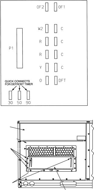
Table 4 — Heat Anticipator Settings
|
|
|
|
|
|
UNIT VOLTAGE |
|
|
|
|
|
||
|
|
208/230 |
|
|
460 |
|
|
|
575 |
|
|
||
UNIT |
Heater |
Configuration |
Heater |
Configuration |
Heater |
Configuration |
|||||||
|
|
2-Stage |
|
2-Stage |
|
2-Stage |
|||||||
|
kW* |
1-Stage |
kW* |
1-Stage |
kW* |
1-Stage |
|||||||
|
Stage 1 |
Stage 2 |
Stage 1 |
Stage 2 |
Stage 1 |
Stage 2 |
|||||||
|
10.4, 16.0 |
0.3 |
NA |
NA |
13.9, 16.5 |
0.3 |
NA |
NA |
17.0, 34.0 |
0.3 |
NA |
NA |
|
50TFQ |
24.8, 32.0 |
0.6 |
0.3 |
0.3 |
27.8, 33.0 |
||||||||
|
|
|
|
|
|
|
|||||||
|
42.4, 50.0 |
0.9 |
0.6 |
0.3 |
41.7, 50.0 |
0.6 |
0.3 |
0.3 |
51.0 |
0.6 |
0.3 |
0.3 |
|
*kW is based on 240, 480, or 575 v.
CONVENIENCE OUTLET — An optional convenience outlet provides power for rooftop use. For maintenance personnel safety, the convenience outlet power is off when the unit disconnect is off. Adjacent unit outlets may be used for service tools. An optional “Hot Outlet” is available from the factory as a special order item.
NOVAR CONTROLS — Optional Novar controls (ETM 3051) are available for replacement or new construction jobs.
MANUAL OUTDOOR-AIR DAMPER — The outdoor-air hood and screen are attached to the basepan at the bottom of the unit (for shipping).
Assembly:
1.Determine the amount of ventilation required for building. Record the amount for use in Step 8.
2.Remove the filter access panel by raising the panel and swinging it outward. The panel is now disengaged from the track and can be removed. No tools are required to remove the filter access panel. Remove the outdoor-air opening panel. Save the panels and screws. See Fig. 11.
3.Separate the hood and screen from the basepan by removing the screws and brackets securing them. Save all screws and discard the brackets.
4.Replace the outdoor air opening panel.
5.Place the hood on the front of the outdoor air opening panel. See Fig. 12 for hood details. Secure the top of the hood with the 6 screws removed in Step 3. See Fig. 13.
6.Remove and save the 8 screws (4 on each side) from the sides of the manual outdoor-air damper.
7.Align the screw holes on the hood with the screw holes on the side of the manual outdoor-air damper. See Fig. 12 and 13. Secure the hood with the 8 screws from Step 6.
8.Adjust the minimum position setting of the damper blade by adjusting the manual outdoor-air adjustment screws on the front of the damper blade. See Fig. 11. Slide the blade vertically until it is in the appropriate position determined by Fig. 14. Tighten the screws.
9.Remove and save the screws currently on the sides of hood. Insert the screen. Secure the screen to the hood using the screws. See Fig. 13.
10.Replace the filter access panel. Ensure that the filter access panel slides along the tracks and is securely engaged.
Fig. 10 — Defrost Board
FILTER
ACCESS
PANEL
OUTDOOR AIR
OPENING
PANEL
SCREWS  (SIDE)
MANUAL OUTDOOR-AIR ADJUSTMENT
SCREWS DAMPER BLADE
Fig. 11 — Damper Panel with Manual
Outdoor-Air Damper Installed
13
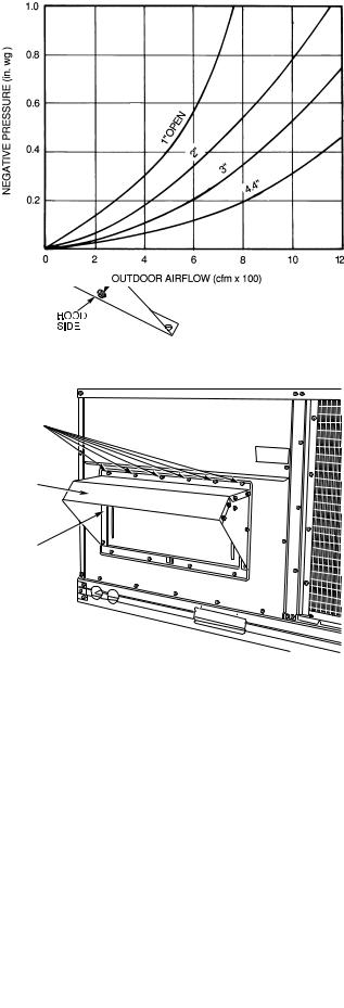
Fig. 12 — Outdoor-Air Hood Details
SCREW HOLES (TOP)
HOOD
HOOD SCREEN LOCATION (SCREEN NOT SHOWN)
Fig. 13 — Optional Manual Outdoor-Air
Damper with Hood Attached
Fig. 14 — Outdoor Air Damper Position Setting
PREMIERLINK™ CONTROL — The PremierLink controller is compatible with Carrier Comfort Network® (CCN) devices. This control is designed to allow users the access and ability to change factory-defined settings, thus expanding the function of the standard unit control board. Carrier’s diagnostic standard tier display tools such as Navigator™ module or Scrolling Marquee can be used with the PremierLink controller.
The PremierLink controller (see Fig. 15A and 15B) requires a Carrier electronic thermostat or a CCN connection for time broadcast to initiate its internal timeclock. This is necessary for broadcast of time of day functions (occupied/unoccupied). Refer to Fig. 16. The PremierLink control may be mounted in the control panel or an area below the control panel.
NOTE: PremierLink versions 1.3 and later are shipped in Sensor mode. If used with a thermostat, the PremierLink control must be configured to Thermostat mode.
The PremierLink control includes a supply-air temperature sensor (SAT) and an outdoor-air temperature sensor (OAT) as standard. An indoor-air quality (CO2) sensor can be added as an option. Refer to Table 5 for sensor usage.
Install the Supply Air Temperature (SAT) Sensor — When the unit is supplied with a factory-mounted PremierLink control, the supply-air temperature (SAT) sensor (33ZCSENSAT) is factory-supplied and wired. The wiring is routed from the PremierLink control over the control box, through a grommet, into the fan section, down along the back side of the fan, and along the fan deck over to the supply-air opening.
The SAT probe is wire-tied to the supply-air opening (on the horizontal opening end) in its shipping position. Remove the sensor for installation. Re-position the sensor for installation. Re-position the sensor in the flange of the supply-air opening or in the supply air duct (as required by local codes). Drill or punch a 1/2-in. hole in the flange or duct. Use two fieldsupplied, self-drilling screws to secure the sensor probe in a horizontal orientation.
NOTE: The sensor must be mounted in the discharge airstream downstream of the cooling coil and any heating devices. Be sure that the probe tip does not come in contact with any of the unit or heat surfaces.
Outdoor Air Temperature (OAT) Sensor — When the unit is supplied with a factory-mounted PremierLink control, the outdoor-air temperature (OAT) sensor is factory-supplied and wired.
Install the Indoor Air Quality (CO2) Sensor — Mount the optional indoor air quality (CO2) sensor according to manufacturer specifications.
A separate field-supplied transformer must be used to power the CO2 sensor.
Wire the CO2 sensor to the COM and IAQI terminals of J5 on the PremierLink controller. Refer to the PremierLink Installation, Start-up, and Configuration Instructions for detailed wiring and configuration information.
14

Table 5 — PremierLink™ Sensor Usage
APPLICATION |
OUTDOOR AIR |
RETURN AIR |
OUTDOOR AIR |
RETURN AIR |
|
TEMPERATURE SENSOR |
TEMPERATURE SENSOR |
ENTHALPY SENSOR |
ENTHALPY SENSOR |
||
|
|||||
Dry Bulb |
|
|
|
|
|
Temperature with |
|
|
|
|
|
PremierLink™* |
Included — |
— |
— |
— |
|
(PremierLink |
HH79NZ017 |
||||
|
|
|
|||
requires 4-20 mA |
|
|
|
|
|
Actuator) |
|
|
|
|
|
Differential Dry Bulb |
|
|
|
|
|
Temperature with |
|
Required — |
|
|
|
PremierLink* |
Included — |
|
|
||
33ZCT55SPT |
— |
— |
|||
(PremierLink |
HH79NZ017 |
||||
or Equivalent |
|
|
|||
requires 4-20 mA |
|
|
|
||
|
|
|
|
||
Actuator) |
|
|
|
|
|
Single Enthalpy with |
|
|
|
|
|
PremierLink* |
Included — |
|
Required — |
|
|
(PremierLink |
— |
— |
|||
Not Used |
HH57AC077 |
||||
requires 4-20 mA |
|
|
|||
|
|
|
|
||
Actuator) |
|
|
|
|
|
Differential Enthalpy |
|
|
|
|
|
with PremierLink* |
Included — |
|
Required — |
Required — |
|
(PremierLink |
— |
||||
Not Used |
HH57AC077 |
HH57AC078 |
|||
requires 4-20 mA |
|
||||
|
|
|
|
||
Actuator) |
|
|
|
|
*PremierLink control requires Supply Air Temperature sensor 33ZCSENSAT and
Outdoor Air Temperature Sensor HH79NZ017 — Included with factory-installed PremierLink control; field-supplied and field-installed with field-installed PremierLink control.
NOTES:
1.CO2 Sensors (Optional):
33ZCSENCO2 — Room sensor (adjustable). Aspirator box is required for duct mounting of the sensor.
33ZCASPCO2 — Aspirator box used for duct-mounted CO2 room sensor. 33ZCT55CO2 — Space temperature and CO2 room sensor with override. 33ZCT56CO2 — Space temperature and CO2 room sensor with override and set point.
2.All units include the following Standard Sensors:
Outdoor-Air Sensor — 50HJ540569 — Opens at 67 F, closes at 52 F, not adjustable.
Mixed-Air Sensor — HH97AZ001 — (PremierLink control requires Supply Air Temperature sensor 33ZCSENSAT and Outdoor Air Temperature Sensor HH79NZ017)
Compressor Lockout Sensor — 50HJ540570 — Opens at 35 F, closes at 50 F.
Fig. 15A — PremierLink Controller
15
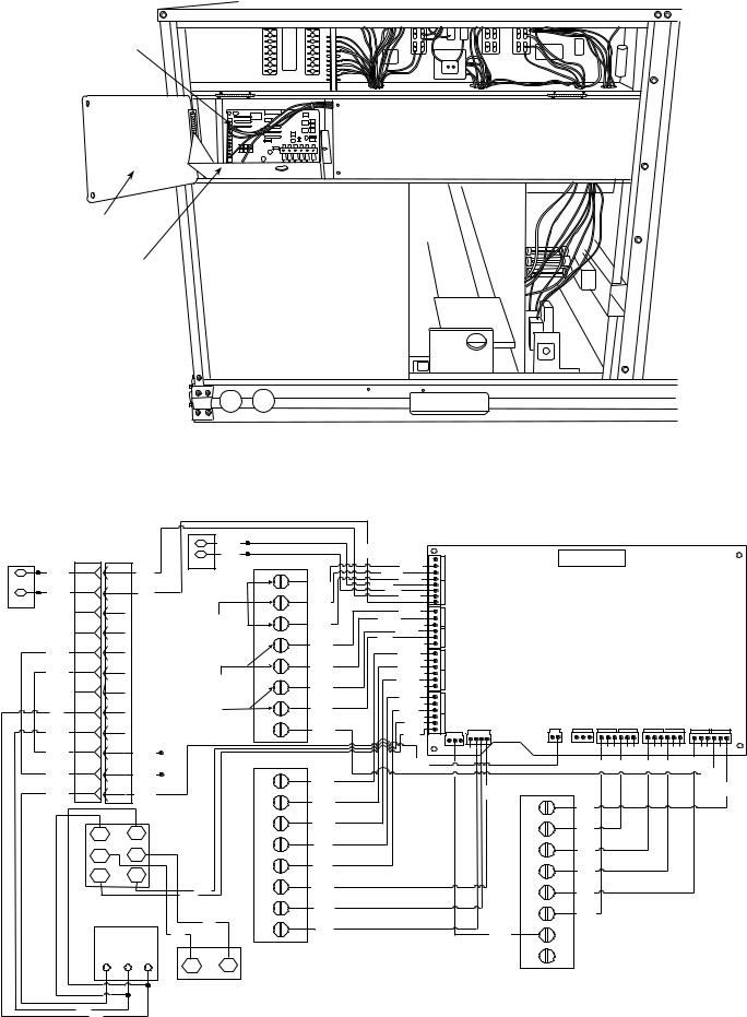
PREMIERLINK
CONTROL
HINGED
DOOR
PANEL
PREMIERLINK
COVER
Fig. 15B — PremierLink™ Controller (Installed)
|
|
|
|
BLK |
|
|
VIO |
|
|
|
|
|
|
|
|
|
|
RED |
|
|
|
|
|
|
HK50AA039 |
||
|
|
|
|
TB - 2 |
|
|
|
|
|
|
|||
PNK |
7 |
7 |
PNK |
SAT |
|
BLU |
ANAL |
J6 |
|
|
|||
|
|
|
BLK |
|
|
|
|
||||||
|
|
|
|
|
1 |
BLU |
BRN |
OG |
|
|
|
PremierLink |
|
VIO |
|
|
VIO |
|
|
|
ORN |
|
|
|
|||
6 |
6 |
|
2 |
|
PNK |
|
|
|
|
||||
OAT |
|
|
|
|
BRN |
BRN |
|
|
|
|
|
|
|
|
|
|
|
|
|
|
0 |
|
|
|
|
|
|
|
11 |
11 |
|
Space Temp./ Set |
3 |
|
RED |
- |
|
|
|
|
|
|
|
BLK |
mA20 |
J5 |
|
|
|
|
|||||
|
|
|
|
Point Adjustment |
BRN |
|
|
|
|
||||
|
|
|
|
|
|
|
|
|
|
|
|
|
|
|
10 |
10 |
|
|
4 |
BRN |
BLU |
IN |
|
|
|
|
|
YEL |
|
|
|
|
GRN |
|
|
|
|
|
|
||
8 |
8 |
|
|
|
|
|
|
|
|
|
|
||
|
|
|
5 |
RED |
|
|
|
|
|
|
|
||
BLU |
|
|
|
|
YEL |
|
|
|
|
|
|
||
3 |
3 |
|
Indoor Air |
|
|
WHT |
DISCRETE |
J4 |
|
|
|
|
|
|
2 |
2 |
|
6 |
|
BLU |
|
|
|
|
|
|
|
|
|
|
|
Quality Sensor |
BRN |
|
|
|
|
|
|
||
|
|
|
|
|
|
|
|
|
|
|
|||
BLK |
4 |
4 |
|
Outdoor Air |
7 |
BLU |
PNK |
|
|
|
|
J9 |
J7 |
|
|
|
|
GRA |
|
|
J2 |
|
|||||
|
|
|
|
Quality Sensor |
8 |
ORN |
J1 |
|
|
0-20 mA |
PP/MP |
||
RED |
1 |
1 |
|
Power Exhaust/Energy Recycler |
GRA |
PWR COMMS |
|
|
|
||||
|
|
|
|
|
|
|
|
|
|
|
|
||
BLU |
5 |
5 |
GRA |
|
TB - 3 |
|
|
|
|
|
|
|
|
|
|
|
|
PNK |
|
|
|
|
|
|
|||
|
|
|
|
|
|
BRN |
|
|
|
WHT GRA |
|||
YEL |
|
|
ORN |
|
|
|
|
|
|
|
|||
9 |
9 |
RMTOCC |
1 |
GRN |
|
|
|
|
|
|
|
||
|
|
GRA |
BLK |
|
RED |
TB - 1 |
|
||||||
WHT |
|
|
|
|
|
|
|
|
|
||||
12 |
12 |
PNK |
|
2 |
|
|
|
|
|
||||
|
YEL |
|
|
|
|
1 |
R |
|
|||||
|
|
CMPSAFE |
|
|
|
|
|
||||||
|
|
|
|
|
|
|
|
RED |
|||||
|
TR |
|
TR1 |
FSD |
3 |
BLU |
|
|
|
|
2 |
Y1 |
GRA |
|
|
|
|
|
|
|
|
|
3 |
|
|
||
|
|
|
|
SFS |
4 |
WHT |
|
|
|
|
Y2 |
|
|
|
|
|
+ |
|
|
|
|
|
ORN |
||||
|
SR |
|
|
|
|
|
|
|
|
|
|
|
|
|
|
|
|
5 |
|
|
|
|
|
|
|
|
|
|
2 |
|
3 |
|
PNK |
|
|
|
|
4 |
W1 |
ORN |
|
|
|
|
|
|
|
|
|
|
|
|
|||
|
|
|
6 |
|
|
|
|
|
|
|
|
||
|
|
|
|
GRAY |
RED |
|
|
|
|
5 |
W2 |
|
|
|
|
|
|
|
|
|
|
|
PNK |
||||
|
OUTDOOR AIR |
GRAY |
|
|
|
|
|
|
|
|
|
||
|
|
7 |
|
|
|
|
|
6 |
|
|
|||
|
ENTHALPY SENSOR |
CCN |
WHT |
|
|
|
|
G |
|
||||
|
|
|
|
Comm. |
|
|
|
|
|
|
|
WHT |
|
|
|
|
|
BLK |
8 |
BLK |
|
|
|
|
7 |
C |
|
|
Economi$er2 |
RED |
|
|
|
BRN |
|
||||||
|
|
4 - 20mA |
|
|
|
|
|
|
|
|
|
|
|
|
|
|
LEGEND |
8 |
X |
|
+ |
|
|
|
|
S |
COMMS — Communications |
|
|
||
|
|
RTU Terminal |
|||
RETURN AIR |
OAT |
— Outdoor Air Temperature Sensor |
|
Board |
|
ENTHALPY |
|
PWR |
— Power |
|
|
SENSOR |
|
|
|
||
RED |
|
SAT |
— Supply Air Temperature Sensor |
|
|
BRN |
|
|
|
|
|
Fig. 16 — Typical PremierLink Controls Wiring
16
J8
Relays
ORN ORN PNK
ORN
RED

Enthalpy Sensors and Control — The enthalpy control (HH57AC077) is supplied as a field-installed accessory to be used with the economizer damper control option. The outdoor air enthalpy sensor is part of the enthalpy control. The separate field-installed accessory return air enthalpy sensor (HH57AC078) is required for differential enthalpy control.
NOTE: The enthalpy control must be set to the “D” setting for differential enthalpy control to work properly.
The enthalpy control receives the indoor and return enthalpy from the outdoor and return air enthalpy sensors and provides a dry contact switch input to the PremierLink™ controller. Locate the controller in place of an existing economizer controller or near the actuator. The mounting plate may not be needed if existing bracket is used.
A closed contact indicates that outside air is preferred to the return air. An open contact indicates that the economizer should remain at minimum position.
Outdoor Air Enthalpy Sensor/Enthalpy Controller (HH57AC077) — To wire the outdoor air enthalpy sensor, perform the following (see Fig. 17 and 18):
NOTE: The outdoor air sensor can be removed from the back of the enthalpy controller and mounted remotely.
1.Use a 4-conductor, 18 or 20 AWG cable to connect the enthalpy control to the PremierLink controller and power transformer.
2.Connect the following 4 wires from the wire harness located in rooftop unit to the enthalpy controller:
a.Connect the BRN wire to the 24 vac terminal (TR1) on enthalpy control and to pin 1 on 12-pin harness.
b.Connect the RED wire to the 24 vac GND terminal (TR) on enthalpy sensor and to pin 4 on 12-pin harness.
c.Connect the GRAY/ORN wire to J4-2 on PremierLink controller and to terminal (3) on enthalpy sensor.
d.Connect the GRAY/RED wire to J4-1 on PremierLink controller and to terminal (2) on enthalpy sensor.
NOTE: If installing in a Carrier rooftop, use the two gray wires provided from the control section to the economizer to connect PremierLink controller to terminals 2 and 3 on enthalpy sensor.
If NOT using Carrier equipment, wires may need to be field supplied and installed.
Return Air Enthalpy Sensor — Mount the return-air enthalpy sensor (HH57AC078) in the return-air duct. The return air sensor is wired to the enthalpy controller (HH57AC077). The outdoor enthalpy changeover set point is set at the controller.
To wire the return air enthalpy sensor, perform the following (see Fig. 17):
1.Use a 2-conductor, 18 or 20 AWG, twisted pair cable to connect the return air enthalpy sensor to the enthalpy controller.
2.At the enthalpy control remove the factory-installed resistor from the (SR) and (+) terminals.
3.Connect the field-supplied RED wire to (+) spade connector on the return air enthalpy sensor and the (SR+) terminal on the enthalpy controller. Connect the BLK wire to (S) spade connector on the return air enthalpy sensor and the (SR) terminal on the enthalpy controller.
ENTHALPY CONTROLLER |
RED |
|
|
|
|
|
S (OUTDOOR |
||||
|
|
|
|
|
|
|
|
|
+ |
AIR |
|
|
|
|
|
BRN |
|
|
|
|
|
||
A B C |
TR |
TR1 |
|
|
BLK |
|
|
ENTHALPY |
|||
|
|
|
|
|
|
SENSOR) |
|||||
|
|
|
|
|
|
|
|
|
|
||
D |
SO |
+ |
|
|
|
RED |
|
|
|
|
|
|
|
|
|
|
|
|
|
||||
|
SR |
+ |
|
|
|
|
|
|
|
S (RETURN AIR |
|
|
|
|
|
|
|
|
|
|
|
+ |
ENTHALPY |
|
2 |
3 |
|
|
|
|
|
|
|
|
SENSOR) |
|
1 |
|
|
GRAY/ORN |
|
|
|
||||
|
|
|
|
|
|
||||||
|
|
|
|
|
|
|
|||||
LED |
|
|
|
|
|
|
|
|
WIRE HARNESS |
||
|
|
|
|
GRAY/RED |
IN UNIT |
|
|||||
|
|
|
|
|
|
||||||
|
|
|
|
|
|
|
|
||||
|
|
|
|
|
|
|
|
|
|
|
|
NOTES:
1.Remove factory-installed jumper across SR and + before connecting wires from return air sensor.
2.Switches shown in high outdoor air enthalpy state. Terminals 2 and 3 close on low outdoor air enthalpy relative to indoor air enthalpy.
3.Remove sensor mounted on back of control and locate in outdoor airstream.
Fig. 17 — Outdoor and Return Air Sensor Wiring Connections for Differential Enthalpy Control
HH57AC077
ENTHALPY
CONTROL AND
BRACKET OUTDOOR AIR
ENTHALPY
SENSOR
HH57AC078 ENTHALPY |
|
SENSOR (USED WITH |
|
ENTHALPY CONTROL |
C7400A1004 |
FOR DIFFERENTIAL |
|
ENTHALPY OPERATION) |
+ |
MOUNTING PLATE
Fig. 18 — Differential Enthalpy Control, Sensor and Mounting Plate (33AMKITENT006)
17
 Loading...