


50SS018-060 50SX024-060 Single-Package Cooling Units
Installation, Start-Up and
Service Instructions
CONTENTS
Page
SAFETY CONSIDERATIONS . . . . . . . . . . . . . . . . . 1-12
General . . . . . . . . . . . . . . . . . . . . . . . . . . . . . . . . . . . . . . 1
RECEIVING AND INSTALLATION . . . . . . . . . . . 13-26
Step 1 Ð Check Equipment . . . . . . . . . . . . . . . . . . 13
·IDENTIFY UNIT
·INSPECT SHIPMENT
Step 2 Ð Provide Unit Support . . . . . . . . . . . . . . 13
·ROOF CURB
·SLAB MOUNT
Step 3 Ð Provide Clearances . . . . . . . . . . . . . . . . 13 Step 4 Ð Rig and Place Unit . . . . . . . . . . . . . . . . . 13
·UNITS WITHOUT BASE RAILS
·UNITS WITH OPTIONAL BASE RAILS
Step 5 Ð Select and Install Ductwork . . . . . . . . 16
·CONVERTING HORIZONTAL DISCHARGE
UNITS TO DOWNFLOW (VERTICAL) DISCHARGE
ÐSTD (NON-ICM) UNITS
·CONVERTING HORIZONTAL DISCHARGE UNITS TO DOWNFLOW (VERTICAL) DISCHARGE
ÐICM UNITS
·ACCESSORY DUCT FLANGE KIT INSTALLATION
Step 6 Ð Provide for Condensate Disposal . . . 20 Step 7 Ð Install Electrical Connections . . . . . . 21
·HIGH-VOLTAGE CONNECTIONS
·ROUTING POWER LEADS INTO UNIT
·CONNECTING GROUND LEAD TO WIRE-BINDING SCREW
·ROUTING CONTROL POWER WIRES Ð STD NON-ICM UNITS (24 V)
·ROUTING CONTROL POWER WIRES Ð ICM UNITS (24 V)
·SPECIAL PROCEDURES FOR 208-V OPERATION
PRE-START-UP . . . . . . . . . . . . . . . . . . . . . . . . . . . . 26,27
START-UP . . . . . . . . . . . . . . . . . . . . . . . . . . . . . . . . 27-39
Check for Refrigerant Leaks . . . . . . . . . . . . . . . . . 27
Start-Up Cooling Section and
Make Adjustments . . . . . . . . . . . . . . . . . . . . . . . . 27
MAINTENANCE . . . . . . . . . . . . . . . . . . . . . . . . . . . . 40,41 Air Filter . . . . . . . . . . . . . . . . . . . . . . . . . . . . . . . . . . . . 40 Unit Top Removal . . . . . . . . . . . . . . . . . . . . . . . . . . . 40
Evaporator Blower and Motor . . . . . . . . . . . . . . . . 40
Condenser Coil, Evaporator Coil,
and Condensate Drain Pan . . . . . . . . . . . . . . . . 41
Condenser Fan . . . . . . . . . . . . . . . . . . . . . . . . . . . . . 41
Electrical Controls and Wiring . . . . . . . . . . . . . . . 41
Refrigerant Circuit . . . . . . . . . . . . . . . . . . . . . . . . . . 41 Evaporator Air¯ow . . . . . . . . . . . . . . . . . . . . . . . . . . 41 Metering Devices . . . . . . . . . . . . . . . . . . . . . . . . . . . 41 Liquid Line Strainer . . . . . . . . . . . . . . . . . . . . . . . . . 41
TROUBLESHOOTING COOLING CHART . . . . . 42,43
START-UP CHECKLIST . . . . . . . . . . . . . . . . . . . . . CL-1
Fig. 1 Ð Unit 50SX With Optional Base Rail Shown
NOTE TO INSTALLER Ð Before the installation, READ THESE INSTRUCTIONS CAREFULLY AND COMPLETELY. Also, make sure the Owner's Manual and Service Instructions are left with the unit after installation.
SAFETY CONSIDERATIONS
Installation and servicing of air-conditioning equipment can be hazardous due to system pressure and electrical components. Only trained and quali®ed personnel should install, repair, or service air-conditioning equipment.
Untrained personnel can perform basic maintenance functions of cleaning coils and ®lters. All other operations should be performed by trained service personnel. When working on air-conditioning equipment, observe precautions in the literature, tags and labels attached to the unit, and other safety precautions that may apply.
Follow all safety codes. Wear safety glasses and work gloves. Use quenching cloth for unbrazing operations. Have ®re extinguisher available for all brazing operations.
Before performing service or maintenance operations on system, turn off main power to unit. Turn off accessory heater power switch if applicable. Electrical shock can cause personal injury.
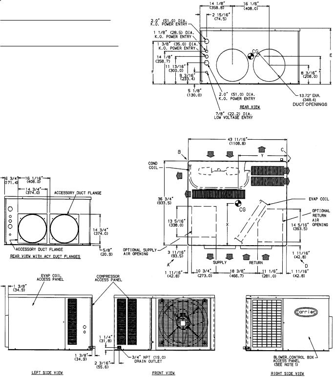
General Ð 50SS,SX cooling units are fully self-contained and designed for outdoor installation. See Fig. 1. As shown in Fig. 2-9, both smalland large-cabinet units are shipped in a horizontal-discharge con®guration for installation on a ground-level slab. All units can be converted to down- ¯ow discharge con®gurations for rooftop applications. See Fig. 10 for roof curb dimensions.
Instructions continued on page 13.
Manufacturer reserves the right to discontinue, or change at any time, speci®cations or designs without notice and without incurring obligations.
Book |
1 |
4 |
|
PC 111 |
Catalog No. 535-022 |
Printed in U.S.A. |
Form 50SS,SX-4SI |
Pg 1 |
5-95 |
Replaces: 50SS,SX-3SI |
Tab |
1b |
6b |
|
|
|
|
|
|
|
|
|
|
|
|
|
|
|
|
|
|
|
REQUIRED CLEARANCES TO COMBUSTIBLE MATERIAL Ð in. (mm)
Unit Top . . . . . . . . . . . . . . . . . . . . . . . . . . . . . . . . 14 (356)
Duct Side of Unit . . . . . . . . . . . . . . . . . . . . . . . . . . . . 2 (51)
Side Opposite Ducts . . . . . . . . . . . . . . . . . . . . . . . . 14 (356)
Bottom of Unit . . . . . . . . . . . . . . . . . . . . . . . . . . . . . . . . . 0
Vertical Discharge First 12 in. (305) of Supply Duct . . . . . . . 1 (25)
NECESSARY REQUIRED CLEARANCES Ð in. (mm)
Between Units, Control Box Side . . . . . . . . . . . . . . . . 42 (1067)
Unit and Ungrounded Surfaces, Control Box Side . . . . . . 36 (914)
Unit and Block or Concrete Walls and Other Grounded
Surfaces, Control Box Side . . . . . . . . . . . . . . . . . . . 42 (1067)
REQUIRED CLEARANCES FOR SERVICING Ð in. (mm)
Evaporator Coil Access Side . . |
. . . . . . . . |
. . . |
. 30 (762). . . . . |
|
|
|||||
Control Box Access Side . . . . . |
. . . . . . . . |
. . . |
. 30 (762). . . . . |
|
|
|||||
|
(Except for Necessary Requirements) |
|
|
|
|
|
||||
Unit Top |
. . |
. |
. . . . . . . . . . . . |
. . . . . . . . |
. . . |
. 36 (914). . . . . |
|
|
||
Side Opposite Ducts . . . . . . . |
. . . . . . . . |
. . . |
. 30 (762). . . . . |
|
|
|||||
|
|
|
|
|
|
|
|
|||
|
UNIT |
|
CENTER OF GRAVITY (in./mm) |
|
||||||
|
50SS |
|
X |
Y |
|
|
Z |
|||
|
018 |
|
19.6/499 |
21.7/551 |
|
10.6/269 |
|
|
||
024 |
|
22.5/570 |
20.9/530 |
|
10.0/254 |
|
|
|||
030 |
|
22.1/561 |
20.3/516 |
|
10.0/253 |
|
|
|||
036 |
|
21.2/538 |
19.9/506 |
|
9.9/251 |
|
|
|||
042 |
|
21.3/540 |
19.9/506 |
|
11.3/286 |
|
|
|||
|
|
|
|
LEGEND |
|
|
|
|
|
|
CG |
Ð Center of Gravity |
NEC |
Ð National Electrical Code |
|||||||
COND |
Ð |
Condenser |
REQ'D |
Ð |
Required |
|||||
MAT'L |
Ð |
Material |
|
|
|
|
|
|
||
NOTES:
1. |
Clearances must be maintained to prevent recirculation of air from |
|
outdoor-fan discharge. |
2. |
Dimensions in ( ) are in millimeters. |
UNIT |
ELECTRICAL |
UNIT WT |
|
CORNER WT (Lb/Kg) |
|
UNIT HEIGHT |
DIMENSION |
||||
|
|
(in./mm) |
(in./mm) |
||||||||
50SS |
CHARACTERISTICS |
|
|
|
|
|
|
|
|
|
|
Lb |
Kg |
A |
|
B |
C |
|
D |
E |
F |
||
|
|
|
|
||||||||
018 |
208/230-1-60 |
208 |
95 |
61/28 |
|
43/20 |
69/31 |
|
35/16 |
24.1/613 |
18.2/462 |
024 |
208/230-1-60 |
237 |
108 |
60/27 |
|
54/25 |
92/42 |
|
31/14 |
24.1/613 |
18.2/462 |
030 |
208/230-1-60, 208/230-3-60 |
254 |
115 |
61/28 |
|
58/26 |
96/44 |
|
39/18 |
24.1/613 |
18.2/462 |
036 |
208/230-1-60, 208/230-3-60, 460-3-60 |
270 |
123 |
75/35 |
|
48/22 |
109/50 |
|
37/17 |
24.1/613 |
18.2/462 |
042 |
208/230-1-60, 208/230-3-60, 460-3-60 |
300 |
135 |
81/40 |
|
57/26 |
117/53 |
|
45/20 |
28.1/714 |
22.2/563 |
Fig. 2 Ð Dimensions; Units 50SS018-042 Without Base Rail
2
REQUIRED CLEARANCES TO COMBUSTIBLE MATERIAL Ð in. (mm)
Unit Top . . . . . . . . . . . . . . . . . . . . . . . . . . . . . . . . 14 (356)
Duct Side of Unit . . . . . . . . . . . . . . . . . . . . . . . . . . . . 2 (51)
Side Opposite Ducts . . . . . . . . . . . . . . . . . . . . . . . . 14 (356)
Bottom of Unit . . . . . . . . . . . . . . . . . . . . . . . . . . . . . . . . . 0
Vertical Discharge First 12 in. (305) of Supply Duct . . . . . . . 1 (25)
NECESSARY REQUIRED CLEARANCES Ð in. (mm)
Between Units, Control Box Side . . . . . . . . . . . . . . . . 42 (1067)
Unit and Ungrounded Surfaces, Control Box Side . . . . . . 36 (914)
Unit and Block or Concrete Walls and Other Grounded
Surfaces, Control Box Side . . . . . . . . . . . . . . . . . . . 42 (1067)
REQUIRED CLEARANCES FOR SERVICING Ð in. (mm)
Evaporator Coil Access Side . |
. . . . . . . . . |
. . . 30 (762). . . . . . |
||||||
Control Box Access Side . . . . |
. . . . . . . . . |
. . . 30 (762). . . . . . |
||||||
|
(Except for Necessary Requirements) |
|
|
|
||||
Unit Top |
. . |
. |
. . . . . . . . . . . |
. . . . . . . . . |
. . . 36 (914). . . . . . |
|||
Side Opposite Ducts . . . . . . |
. . . . . . . . . |
. . . 30 (762). . . . . . |
||||||
|
|
|
|
|
|
|
||
|
UNIT |
|
CENTER OF GRAVITY (in./mm) |
|
||||
|
50SS |
|
X |
Y |
|
Z |
||
|
018 |
|
19.5/495 |
21.7/551 |
|
12.9/328 |
|
|
024 |
|
22.1/562 |
20.9/532 |
|
12.3/313 |
|
||
030 |
|
21.8/554 |
20.4/519 |
|
12.3/312 |
|
||
036 |
|
21.0/533 |
20.1/509 |
|
12.2/310 |
|
||
042 |
|
21.0/532 |
20.1/510 |
|
13.6/344 |
|
||
|
|
|
|
LEGEND |
|
|
|
|
CG |
Ð Center of Gravity |
NEC |
Ð National Electrical Code |
|||||
COND |
Ð |
Condenser |
REQ'D |
Ð Required |
||||
MAT'L |
Ð |
Material |
|
|
|
|
||
NOTES:
1. |
Clearances must be maintained to prevent recirculation of air from |
|
outdoor-fan discharge. |
2. |
Dimensions in ( ) are in millimeters. |
UNIT |
ELECTRICAL |
UNIT WT |
|
CORNER WT (Lb/Kg) |
|
UNIT HEIGHT |
DIMENSION |
||||
|
|
(in./mm) |
(in./mm) |
||||||||
50SS |
CHARACTERISTICS |
|
|
|
|
|
|
|
|
|
|
Lb |
Kg |
A |
|
B |
C |
|
D |
E |
F |
||
|
|
|
|
||||||||
018 |
208/230-1-60 |
228 |
104 |
66/30 |
|
48/22 |
74/34 |
|
40/18 |
27.4/697 |
21.5/546 |
024 |
208/230-1-60 |
257 |
117 |
65/30 |
|
59/27 |
97/44 |
|
36/16 |
27.4/697 |
21.5/546 |
030 |
208/230-1-60, 208/230-3-60 |
274 |
125 |
66/30 |
|
63/29 |
101/46 |
|
44/20 |
27.4/697 |
21.5/546 |
036 |
208/230-1-60, 208/230-3-60, 460-3-60 |
290 |
132 |
81/37 |
|
53/24 |
114/52 |
|
42/19 |
27.4/697 |
21.5/546 |
042 |
208/230-1-60, 208/230-3-60, 460-3-60 |
320 |
146 |
86/39 |
|
62/28 |
122/55 |
|
50/23 |
31.4/798 |
25.5/648 |
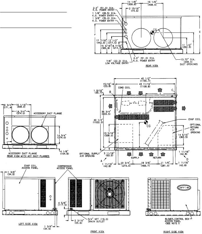
Fig. 3 Ð Dimensions; Units 50SS018-042 with Optional Base Rail
3
REQUIRED CLEARANCES TO COMBUSTIBLE MATERIAL Ð in. (mm) |
|
||
Unit Top . . . . . . . . . . . . . . . . . . . . . . . . . . . . . . . . . . |
. . 14 (356) |
||
Duct Side of Unit . . . . . . . . . . . . . . . . . . . . . . . . . . . . . |
. . . . 2 (51) |
||
Side Opposite Ducts . . . . . . . . . . . . . . . . . . . . . . . . . . . |
. . 14 (356) |
||
Bottom of Unit . . . . . . . . . . . . . . . . . . . . . . . . . . . . . . . |
. . . . . . 0 |
||
Vertical Discharge First 12 in. (305) of Supply Duct . . . . . . . . . . . |
. . . . 1 (25) |
||
NECESSARY REQUIRED CLEARANCES Ð in. (mm) |
|
|
|
Between Units, Control Box Side . . . . . . . . . . . . . . . . . . . . |
. . 42 (1067) |
||
Unit and Ungrounded Surfaces, Control Box Side . . . . . . . . . . . . |
. . 36 (914) |
||
Unit and Block or Concrete Walls and Other Grounded |
|
||
Surfaces, Control Box Side . . . . . . . . . . . . . . . . . . . . . . . |
. . 42 (1067) |
||
REQUIRED CLEARANCES FOR SERVICING Ð in. (mm) |
|
|
|
Evaporator Coil Access Side . . . . . . . . . . . . . . . . . . . . . . . |
. . 30 (762) |
||
Control Box Access Side . . . . . . . . . . . . . . . . . . . . . . . . . |
. . 30 (762) |
||
(Except for Necessary Requirements) |
|
||
Unit Top . . . . . . . . . . . . . . . . . . . . . . . . . . . . . . . . . . |
. . 36 (914) |
||
Side Opposite Ducts . . . . . . . . . . . . . . . . . . . . . . . . . . . |
. . 30 (762) |
||
UNIT |
|
|
|
CENTER OF GRAVITY (in./mm) |
||||
50SS |
|
|
X |
|
|
Y |
|
Z |
048 |
|
|
21.9/555 |
|
19.6/498 |
|
13.4/341 |
|
060 |
|
|
22.2/565 |
|
19.8/503 |
|
13.4/340 |
|
|
|
|
|
|
|
|
|
|
|
|
|
|
LEGEND |
|
|
|
|
CG |
Ð |
Center of Gravity |
|
NEC |
Ð |
National Electrical Code |
||
COND |
Ð |
Condenser |
|
REQ'D |
Ð |
Required |
||
MAT'L |
Ð |
Material |
|
|
|
|
|
|
NOTES:
1. |
Clearances must be maintained to prevent recirculation of air from outdoor-fan dis- |
|
charge. |
2. |
Dimensions in ( ) are in millimeters. |
UNIT |
ELECTRICAL |
|
UNIT WT |
|
CORNER WT (Lb/Kg) |
|
||
50SS |
CHARACTERISTICS |
Lb |
|
Kg |
A |
B |
C |
D |
|
|
|
|
|
|
|
|
|
048 |
208/230-1-60, 208/230-3-60, 460-3-60 |
332 |
|
151 |
82/37 |
68/31 |
131/60 |
51/23 |
060 |
208/230-1-60, 208/230-3-60, 460-3-60 |
359 |
|
163 |
65/30 |
99/45 |
120/55 |
75/34 |
Fig. 4 Ð Dimensions; Units 50SS048,060 Without Base Rail
4
REQUIRED CLEARANCES TO COMBUSTIBLE MATERIAL Ð in. (mm)
Unit Top . . . . . . . . . . . . . . . . . . . . . . . . . . . . . . . . . |
. 14 (356) |
|
Duct Side of Unit . . . . . . . . . . . . . . . . . . . . . . . . . . . . |
. . 2 (51) |
|
Side Opposite Ducts . . . . . . . . . . . . . . . . . . . . . . . . . . |
. 14 (356) |
|
Bottom of Unit . . . . . . . . . . . . . . . . . . . . . . . . . . . . . . |
. . . . 0 |
|
Vertical Discharge First 12 in. (305) of Supply Duct . . . . . . . . . . |
. . 1 (25) |
|
NECESSARY REQUIRED CLEARANCES Ð in. (mm) |
|
|
Between Units, Control Box Side . . . . . . . . . . . . . . . . . . . . |
42 (1067) |
|
Unit and Ungrounded Surfaces, Control Box Side . . . . . . . . . . . . |
36 (914) |
|
Unit and Block or Concrete Walls and Other Grounded |
|
|
Surfaces, Control Box Side . . . . . . . . . . . . . . . . . . . . . . |
42 (1067) |
|
REQUIRED CLEARANCES FOR SERVICING Ð in. (mm)
Evaporator Coil Access Side . . . . . . . . . . . . . . . . . . . . . . . 30 (762) Control Box Access Side . . . . . . . . . . . . . . . . . . . . . . . . . 30 (762)
(Except for Necessary Requirements)
Unit Top . . . . . . . . . . . . . . . . . . . . . . . . . . . . . . . . . . 36 (914) Side Opposite Ducts . . . . . . . . . . . . . . . . . . . . . . . . . . . 30 (762)
UNIT |
|
|
|
CENTER OF GRAVITY (in./mm) |
||||
50SS |
|
|
X |
|
|
Y |
|
Z |
048 |
|
|
21.7/550 |
|
19.7/501 |
|
15.7/400 |
|
060 |
|
|
22.0/560 |
|
19.9/506 |
|
15.7/399 |
|
|
|
|
|
|
|
|
|
|
|
|
|
|
LEGEND |
|
|
|
|
CG |
Ð |
Center of Gravity |
|
NEC |
Ð |
National Electrical Code |
||
COND |
Ð |
Condenser |
|
REQ'D |
Ð |
Required |
||
MAT'L |
Ð |
Material |
|
|
|
|
|
|
NOTES:
1.Clearances must be maintained to prevent recirculation of air from outdoor-fan discharge.
2. Dimensions in ( ) are in millimeters.
UNIT |
ELECTRICAL |
UNIT WT |
|
CORNER WT (Lb/Kg) |
|
|||
50SS |
CHARACTERISTICS |
Lb |
Kg |
A |
B |
C |
|
D |
|
|
|
|
|
|
|
|
|
048 |
208/230-1-60, 208/230-3-60, 460-3-60 |
352 |
160 |
87/40 |
73/33 |
136/62 |
|
56/25 |
060 |
208/230-1-60, 208/230-3-60, 460-3-60 |
379 |
172 |
70/32 |
104/47 |
125/57 |
|
80/36 |
Fig. 5 Ð Dimensions; Units 50SS048,060 With Optional Base Rail
5

REQUIRED CLEARANCES TO COMBUSTIBLE MATERIAL Ð in. (mm)
Unit Top . . . . . . . . . . . . . . . . . . . . . . . . . . . . . . . . 14 (356) Duct Side of Unit . . . . . . . . . . . . . . . . . . . . . . . . . . . . 2 (51) Side Opposite Ducts . . . . . . . . . . . . . . . . . . . . . . . . 14 (356) Bottom of Unit . . . . . . . . . . . . . . . . . . . . . . . . . . . . . . . . . 0 Vertical Discharge First 12 in. (305) of Supply Duct . . . . . . . 1 (25)
NECESSARY REQUIRED CLEARANCES Ð in. (mm)
Between Units, Control Box Side . . . . . . . . . . . . . . . . 42 (1067) Unit and Ungrounded Surfaces, Control Box Side . . . . . . 36 (914) Unit and Block or Concrete Walls and Other Grounded
Surfaces, Control Box Side . . . . . . . . . . . . . . . . . . . 42 (1067)
REQUIRED CLEARANCES FOR SERVICING Ð in. (mm) |
|
Evaporator Coil Access Side . . . . . . . . . . . . . . . . . . |
. 30 (762) |
Control Box Access Side . . . . . . . . . . . . . . . . . . . . . |
. 30 (762) |
(Except for Necessary Requirements) |
|
Unit Top . . . . . . . . . . . . . . . . . . . . . . . . . . . . . . . |
. 36 (914) |
Side Opposite Ducts . . . . . . . . . . . . . . . . . . . . . . . |
. 30 (762) |
NOTES:
1.Clearances must be maintained to prevent recirculation of air from outdoor-fan discharge.
2. Dimensions in ( |
) are in millimeters. |
|
|||
|
|
|
|
|
|
|
UNIT |
|
CENTER OF GRAVITY (in./mm) |
||
|
50SX |
|
X |
Y |
Z |
|
024 |
|
21.7/552 |
20.7/527 |
12.7/321 |
030 |
|
21.9/556 |
20.7/525 |
12.7/321 |
|
|
036 |
|
20.8/528 |
20.0/507 |
12.7/321 |
|
|
LEGEND |
|
|
|
CG |
Ð Center of Gravity |
NEC |
Ð |
National Electrical Code |
|
COND |
Ð |
Condenser |
REQ'D |
Ð |
Required |
MAT'L |
Ð |
Material |
|
|
|
UNIT |
ELECTRICAL |
|
UNIT WT |
|
CORNER WT (Lb/Kg) |
|
||
50SX |
CHARACTERISTICS |
Lb |
|
Kg |
A |
B |
C |
D |
024 |
208/230-1-60 |
270 |
|
123 |
67/30 |
62/28 |
99/45 |
42/19 |
030 |
208/230-1-60 |
273 |
|
124 |
66/30 |
64/29 |
100/45 |
43/20 |
036 |
208/230-1-60, 208/230-3-60, 460-3-60 |
291 |
|
132 |
80/36 |
54/25 |
112/51 |
45/20 |
Fig. 6 Ð Dimensions; Units 50SX024-036 Without Base Rail
6

REQUIRED CLEARANCES TO COMBUSTIBLE MATERIAL Ð in. (mm)
Unit Top . . . . . . . . . . . . . . . . . . . . . . . . . . . . . . . . 14 (356) Duct Side of Unit . . . . . . . . . . . . . . . . . . . . . . . . . . . . 2 (51) Side Opposite Ducts . . . . . . . . . . . . . . . . . . . . . . . . 14 (356) Bottom of Unit . . . . . . . . . . . . . . . . . . . . . . . . . . . . . . . . . 0 Vertical Discharge First 12 in. (305) of Supply Duct . . . . . . . 1 (25)
NECESSARY REQUIRED CLEARANCES Ð in. (mm)
Between Units, Control Box Side . . . . . . . . . . . . . . . . 42 (1067) Unit and Ungrounded Surfaces, Control Box Side . . . . . . 36 (914) Unit and Block or Concrete Walls and Other Grounded
Surfaces, Control Box Side . . . . . . . . . . . . . . . . . . . 42 (1067)
REQUIRED CLEARANCES FOR SERVICING Ð in. (mm) |
|
Evaporator Coil Access Side . . . . . . . . . . . . . . . . . . |
. 30 (762) |
Control Box Access Side . . . . . . . . . . . . . . . . . . . . . |
. 30 (762) |
(Except for Necessary Requirements) |
|
Unit Top . . . . . . . . . . . . . . . . . . . . . . . . . . . . . . . |
. 36 (914) |
Side Opposite Ducts . . . . . . . . . . . . . . . . . . . . . . . |
. 30 (762) |
NOTES:
1.Clearances must be maintained to prevent recirculation of air from outdoor-fan discharge.
2. Dimensions in ( |
) are in millimeters. |
|
|||
|
|
|
|
|
|
|
UNIT |
|
CENTER OF GRAVITY (in./mm) |
||
|
50SX |
|
X |
Y |
Z |
|
024 |
|
21.5/546 |
20.8/528 |
15.0/380 |
030 |
|
21.7/550 |
20.7/527 |
15.0/380 |
|
|
036 |
|
20.6/524 |
20.1/510 |
15.0/380 |
|
|
|
LEGEND |
|
|
CG |
Ð Center of Gravity |
NEC |
Ð |
National Electrical Code |
|
COND |
Ð |
Condenser |
REQ'D |
Ð |
Required |
MAT'L |
Ð |
Material |
|
|
|
UNIT |
ELECTRICAL |
|
UNIT WT |
|
CORNER WT (Lb/Kg) |
|
||
50SX |
CHARACTERISTICS |
Lb |
|
Kg |
A |
B |
C |
D |
024 |
208/230-1-60 |
290 |
|
132 |
72/33 |
67/30 |
104/47 |
47/21 |
030 |
208/230-1-60 |
293 |
|
133 |
71/32 |
69/31 |
105/48 |
48/22 |
036 |
208/230-1-60, 208/230-3-60, 460-3-60 |
311 |
|
142 |
85/39 |
59/27 |
117/53 |
50/23 |
Fig. 7 Ð Dimensions; Units 50SX024-036 With Optional Base Rail
7
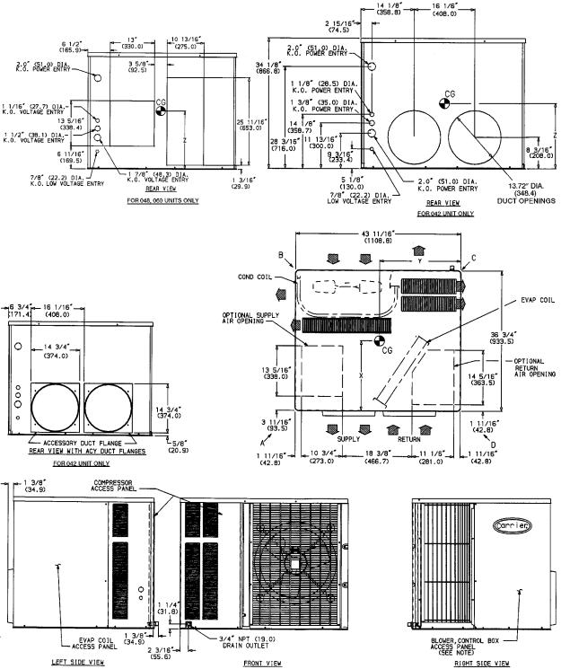
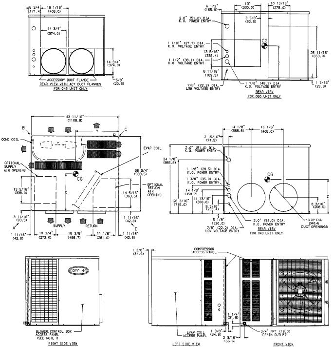
Fig. 8 Ð Dimensions; Units 50SX042-060 Without Base Rail
8

|
|
LEGEND |
|
CG |
Ð Center of Gravity |
NEC Ð National Electrical Code |
|
COND Ð |
Condenser |
REQ'D Ð Required |
|
MAT'L |
Ð |
Material |
|
REQUIRED CLEARANCES TO COMBUSTIBLE MATERIAL Ð in. (mm)
Unit Top . . . . . . . . . . . . . . . . . . . . . . . . . . . . . . . . . . . . . . . . 14 (356)
Duct Side of Unit . . . . . . . . . . . . . . . . . . . . . . . . . . . . . . . . . . . 2 (51)
Side Opposite Ducts . . . . . . . . . . . . . . . . . . . . . . . . . . . . . . . 14 (356)
Bottom of Unit . . . . . . . . . . . . . . . . . . . . . . . . . . . . . . . . . . . . . . . . . 0
Vertical Discharge First 12 in. (305) of Supply Duct . . . . . . . . . . . 1 (25)
NECESSARY REQUIRED CLEARANCES Ð in. (mm) |
|
Between Units, Control Box Side . . . . . . . . . . . . . . . . . |
. . . . 42 (1067) |
Unit and Ungrounded Surfaces, Control Box Side . . . . . . |
. . . . . 36 (914) |
Unit and Block or Concrete Walls and Other Grounded |
|
Surfaces, Control Box Side . . . . . . . . . . . . . . . . . . . . . |
. . . . 42 (1067) |
REQUIRED CLEARANCES FOR SERVICING Ð in. (mm) |
|
Evaporator Coil Access Side . . . . . . . . . . . . . . . . . . . . |
. . . . . 30 (762) |
Control Box Access Side . . . . . . . . . . . . . . . . . . . . . . . |
. . . . . 30 (762) |
(Except for Necessary Requirements) |
|
Unit Top . . . . . . . . . . . . . . . . . . . . . . . . . . . . . . . . . . . |
. . . . . 36 (914) |
Side Opposite Ducts . . . . . . . . . . . . . . . . . . . . . . . . . . |
. . . . . 30 (762) |
NOTES:
1.Clearances must be maintained to prevent recirculation of air from outdoorfan discharge.
2. Dimensions in ( ) are in millimeters.
|
|
UNIT |
CENTER OF GRAVITY (in./mm) |
|
|
|
|
|||||||
|
|
50SX |
X |
|
|
Y |
|
|
|
Z |
|
|
|
|
|
|
042 |
21.0/533 |
|
20.1/510 |
|
15.4/390 |
|
|
|
||||
|
048 |
21.8/553 |
|
19.7/499 |
|
15.4/390 |
|
|
|
|||||
|
060 |
22.2/565 |
|
19.8/503 |
|
13.4/340 |
|
|
|
|||||
|
|
|
|
|
|
|
|
|
|
|
|
|
|
|
UNIT |
|
ELECTRICAL |
UNIT WT |
|
CORNER WT (Lb/Kg) |
|||||||||
50SX |
|
CHARACTERISTICS |
Lb |
|
Kg |
|
A |
|
B |
|
C |
D |
||
042 |
208/230-1-60, 208/230-3-60, 460-3-60 |
309 |
|
140 |
84/38 |
|
59/27 |
119/54 |
47/21 |
|||||
048 |
208/230-1-60, 208/230-3-60, 460-3-60 |
340 |
|
155 |
84/38 |
|
70/32 |
133/60 |
53/24 |
|||||
060 |
208/230-1-60, 208/230-3-60 |
|
359 |
|
163 |
65/30 |
|
99/45 |
120/55 |
75/34 |
||||
Fig. 8 Ð Dimensions; Units 50SX042-060 Without Base Rail (cont)
9
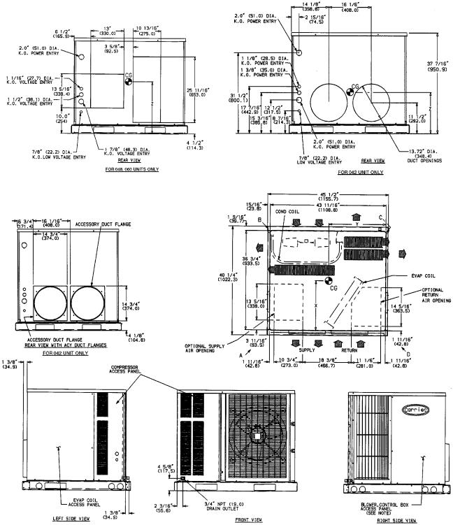
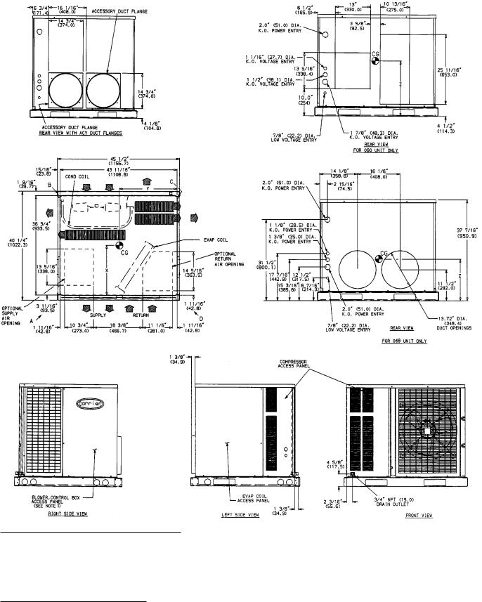
Fig. 9 Ð Dimensions; Units 50SX042-060 With Optional Base Rail
10
|
|
LEGEND |
|
CG |
Ð Center of Gravity |
NEC Ð National Electrical Code |
|
COND Ð |
Condenser |
REQ'D Ð Required |
|
MAT'L |
Ð |
Material |
|
REQUIRED CLEARANCES TO COMBUSTIBLE MATERIAL Ð in. (mm)
Unit Top . . . . . . . . . . . . . . . . . . . . . . . . . . . . . . . . . . . . . . . . 14 (356)
Duct Side of Unit . . . . . . . . . . . . . . . . . . . . . . . . . . . . . . . . . . . 2 (51)
Side Opposite Ducts . . . . . . . . . . . . . . . . . . . . . . . . . . . . . . . 14 (356)
Bottom of Unit . . . . . . . . . . . . . . . . . . . . . . . . . . . . . . . . . . . . . . . . . 0
Vertical Discharge First 12 in. (305) of Supply Duct . . . . . . . . . . . 1 (25)
NECESSARY REQUIRED CLEARANCES Ð in. (mm) |
|
|
Between Units, Control Box Side . . . . . . . . . . . . . . |
. . . |
. . . . 42 (1067) |
Unit and Ungrounded Surfaces, Control Box Side . . . . . . |
. . . . . 36 (914) |
|
Unit and Block or Concrete Walls and Other Grounded |
|
|
Surfaces, Control Box Side . . . . . . . . . . . . . . . . . . . . . |
. . . . 42 (1067) |
|
REQUIRED CLEARANCES FOR SERVICING Ð in. (mm) |
|
|
Evaporator Coil Access Side . . . . . . . . . . . . . . . . . . . . |
. . . . . 30 (762) |
|
Control Box Access Side . . . . . . . . . . . . . . . . . . . . . . . |
. . . . . 30 (762) |
|
(Except for Necessary Requirements) |
|
|
Unit Top . . . . . . . . . . . . . . . . . . . . . . . . . . . . . . . . . . . |
. . . . . 36 (914) |
|
Side Opposite Ducts . . . . . . . . . . . . . . . . . . . . . . . . . . |
. . . . . 30 (762) |
|
NOTES:
1.Clearances must be maintained to prevent recirculation of air from outdoorfan discharge.
2. Dimensions in ( ) are in millimeters.
|
|
UNIT |
CENTER OF GRAVITY (in./mm) |
|
|
|
|
||||||||
|
|
50SX |
X |
|
|
Y |
|
|
|
Z |
|
|
|
|
|
|
|
042 |
20.8/529 |
|
20.2/512 |
|
17.3/440 |
|
|
|
|
||||
|
048 |
21.6/548 |
|
19.8/502 |
|
17.3/440 |
|
|
|
|
|||||
|
|
060 |
22.0/560 |
|
19.9/506 |
|
15.7/399 |
|
|
|
|
||||
|
|
|
|
|
|
|
|
|
|
|
|
||||
UNIT |
|
ELECTRICAL |
UNIT WT |
|
|
CORNER WT (Lb/Kg) |
|
||||||||
50SX |
|
CHARACTERISTICS |
Lb |
|
Kg |
|
A |
|
B |
|
C |
|
D |
||
042 |
208/230-1-60, 208/230-3-60, 460-3-60 |
329 |
|
150 |
89/40 |
|
64/29 |
124/56 |
|
52/24 |
|||||
048 |
208/230-1-60, 208/230-3-60, 460-3-60 |
360 |
|
164 |
89/40 |
|
75/34 |
138/63 |
|
58/26 |
|||||
060 |
208/230-1-60, 208/230-3-60 |
|
379 |
|
172 |
70/32 |
|
104/47 |
125/57 |
|
80/36 |
||||
Fig. 9 Ð Dimensions; Units 50SX042-060 With Optional Base Rail (cont)
11
|
PART NUMBER |
``A'' |
||
FLAT |
CPRFCURB001A00 |
89 |
[203] |
|
CPRFCURB002A00 |
119 |
[279] |
||
CURB |
||||
CPRFCURB003A00 |
149 |
[356] |
||
|
||||
NOTES:
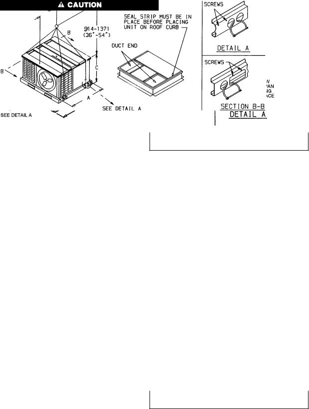
1.Roof curb must be set up for unit being installed.
2.Seal strip must be applied as required for unit being installed.
3. Dimensions in [ ] are in millimeters.
4.Roof curb is made of 16 gage steel.
5.Attach ductwork to curb (¯anges of duct rest on curb).
6.Service clearance 4 ft on each side.
7. direction of air¯ow.
8.Insulated panels, 1-in. thick, ®berglass 1-lb density.
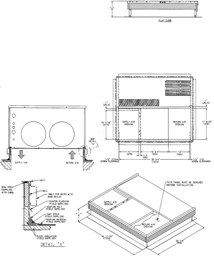
Fig. 10 Ð Roof Curb Dimensions
12
RECEIVING AND INSTALLATION
Step 1 Ð Check Equipment
IDENTIFY UNIT Ð The unit model number and serial number are stamped on the unit identi®cation plate. Check this information against shipping papers.
INSPECT SHIPMENT Ð Inspect for shipping damage while unit is still on shipping pallet. If unit appears to be damaged or is torn loose from its anchorage, have it examined by transportation inspectors before removal. Forward claim papers directly to transportation company. Manufacturer is not responsible for any damage incurred in transit.
Check all items against shipping list. Immediately notify the nearest Carrier Air Conditioning office if any item is missing.
To prevent loss or damage, leave all parts in original packages until installation.
Step 2 Ð Provide Unit Support
ROOF CURB Ð Install accessory roof curb in accordance with instructions shipped with curb. See Fig. 10. Install insulation, cant strips, roo®ng, and ¯ashing. Ductwork must be attached to curb.
IMPORTANT: The gasketing of the unit to the roof curb is critical for a watertight seal. Install gasketing material supplied with the roof curb. Improperly applied gasketing also can result in air leaks and poor unit performance.
Curb should be level to within 1¤4 inch. This is necessary for unit drain to function properly. Refer to accessory roof curb installation instructions for additional information as required.
SLAB MOUNT Ð Place the unit on a solid, level concrete pad that is a minimum of 4 in. thick with 2 in. above grade. The slab should extend approximately 2 in. beyond the casing on all 4 sides of the unit. Install a 6-in. gravel apron in front of condenser-air inlet to prevent obstruction of air¯ow by grass or shrubs. Do not secure the unit to the slab except when required by local codes.
Step 3 Ð Provide Clearances Ð The required minimum service clearances and clearances to combustibles are shown in Fig. 2-9. Adequate ventilation and condenser air must be provided.
The condenser fan pushes air through the condenser coil and discharges it through louvers on the top cover, the decorative grille, and the compressor access panel. Be sure that the fan discharge does not recirculate to the condenser coil. Do not locate the unit in either a corner or under an overhead obstruction. The minimum clearance under a partial overhang (such as a normal house overhang) is 48 in. above the unit top. The maximum horizontal extension of a partial overhang must not exceed 48 inches.
Do not restrict condenser air¯ow. An air restriction at either the outdoor-air inlet or the fan discharge can be detrimental to compressor life.
Do not place the unit where water, ice, or snow from an overhang or roof will damage or ¯ood the unit. Do not install the unit on carpeting, tile, or other combustible materials. The unit may be installed on wood ¯ooring or on Class A, B, or C roof covering materials.
Step 4 Ð Rig and Place Unit Ð Use spreader bars or crate top when rigging the unit. The units must be rigged for lifting as shown in Fig. 11 and 12. Refer to Fig. 11 and 12 for rigging weights and Tables 1 and 2 for operating weights.
Use extreme caution to prevent damage when moving the unit. Unit must remain in an upright position during all rigging and moving operations. The unit must be level for proper condensate drainage; the ground-level pad or accessory roof curb must be level before setting the unit in place. When a ®eld-fabricated support is used, be sure that the support is level and that it properly supports the unit.
UNITS WITHOUT BASE RAILS Ð Accessory rigging brackets are recommended to be used for rigging. Install brackets as follows:
Secure screws and paint protectors solidly against unit basepan to hold lifting brackets in position.
Never use lifting brackets when the temperature is below −10 F (−23 C).
Never exceed 200 lbs per bracket of lifting force.
Never use lifting brackets for lifting other models of air conditioning units.
Lifting point should be directly over the unit center of gravity.
1.Position brackets as close to the corners of unit as possible. Be sure brackets are well outside of center of gravity. (See Fig. 2, 4, 6, 8, and 11.)
2.Position paint protectors and foam strips between screws and painted surface of unit. Tighten screws until they make contact with the paint protectors.
3.Secure device or hook of sufficient strength to hole in bracket as shown in detail ``A'' of Fig. 11.
4.If wood top is available, use it for a spreader bar to prevent straps from damaging unit. If wood top is not available, use spreader bars of sufficient length.
UNITS WITH OPTIONAL BASE RAILS Ð Keep unit upright and do not drop. Use spreader bars or top crate when rigging unit. Rollers may be used to move unit across roof. Level unit for proper condensate disposal. See Fig. 3, 5, 7, and 9 for additional information. Lifting holes are provided in base rails as shown in Fig. 12. Refer to rigging instructions on unit.
13
NOTICE TO RIGGERS
Hook rigging shackles through holes in lifting brackets, as shown in Detail ``A,'' lifting brackets to be centered around the unit center of gravity. Use wood top skid when rigging, to prevent rigging straps from damaging unit.
All panels must be in place when rigging.
UNIT SIZE |
SHIPPING WEIGHT |
|
A |
|
B |
|
C |
||||
50SS |
Lb |
Kg |
in. |
|
mm |
in. |
|
mm |
in. |
|
mm |
018 |
260 |
118 |
363¤4 |
|
934 |
18 |
|
457 |
241¤8 |
|
613 |
024 |
289 |
131 |
363¤4 |
|
934 |
163¤4 |
|
426 |
241¤8 |
|
613 |
030 |
306 |
139 |
363¤4 |
|
934 |
165¤16 |
|
415 |
241¤8 |
|
613 |
036 |
322 |
146 |
363¤4 |
|
934 |
161¤4 |
|
412 |
241¤8 |
|
613 |
042 |
333 |
151 |
363¤4 |
|
934 |
167¤16 |
|
416 |
281¤8 |
|
714 |
048 |
384 |
174 |
363¤4 |
|
934 |
161¤4 |
|
412 |
341¤8 |
|
867 |
060 |
411 |
186 |
363¤4 |
|
934 |
161¤4 |
|
412 |
341¤8 |
|
867 |
UNIT SIZE |
SHIPPING WEIGHT |
|
A |
|
B |
|
C |
||||
50SX |
Lb |
Kg |
in. |
|
mm |
in. |
|
mm |
in. |
|
mm |
024 |
322 |
146 |
363¤4 |
|
934 |
143¤4 |
|
375 |
281¤8 |
|
714 |
030 |
325 |
147 |
363¤4 |
|
934 |
141¤2 |
|
368 |
281¤8 |
|
714 |
036 |
343 |
155 |
363¤4 |
|
934 |
155¤8 |
|
397 |
281¤8 |
|
714 |
042 |
361 |
164 |
363¤4 |
|
934 |
151¤2 |
|
394 |
341¤8 |
|
867 |
048 |
392 |
178 |
363¤4 |
|
934 |
1411¤16 |
|
373 |
341¤8 |
|
867 |
060 |
411 |
186 |
363¤4 |
|
934 |
161¤4 |
|
412 |
341¤8 |
|
867 |
Fig. 11 Ð Suggested Rigging for Units Without Base Rail
NOTICE TO RIGGERS
Hook rigging shackles through holes in lifting brackets, as shown in Detail ``A,'' lifting brackets to be centered around the unit center of gravity. Use wood top skid when rigging, to prevent rigging straps from damaging unit. Remove 4 screws to slide wood support through rectangular hole in rail.
UNIT SIZE |
SHIPPING |
|
A |
|
B |
|
C |
|||
WEIGHT |
|
|
|
|||||||
50SS |
|
|
|
|
|
|
|
|
||
Lb |
Kg |
in. |
mm |
in. |
|
mm |
in. |
|
mm |
|
|
|
|
||||||||
018 |
247 |
112 |
36.5 |
926.0 |
17.0 |
|
431 |
28.2 |
|
715 |
024 |
276 |
125 |
36.5 |
926.0 |
14.3 |
|
364 |
28.2 |
|
715 |
030 |
293 |
133 |
36.8 |
926.0 |
14.7 |
|
372 |
28.2 |
|
715 |
036 |
309 |
140 |
36.5 |
926.0 |
15.5 |
|
393 |
28.2 |
|
715 |
042 |
339 |
154 |
36.5 |
926.0 |
15.5 |
|
394 |
32.2 |
|
817 |
048 |
371 |
168 |
36.5 |
926.0 |
14.8 |
|
376 |
38.2 |
|
969 |
060 |
398 |
180 |
36.5 |
926.0 |
14.4 |
|
366 |
38.2 |
|
969 |
All panels must be in place when rigging.
UNIT SIZE |
SHIPPING |
|
A |
|
B |
|
C |
|||
WEIGHT |
|
|
|
|||||||
50SX |
|
|
|
|
|
|
|
|
||
Lb |
Kg |
in. |
mm |
in. |
|
mm |
in. |
|
mm |
|
|
|
|
||||||||
024 |
309 |
140 |
36.5 |
926.0 |
15.0 |
|
380 |
32.2 |
|
817 |
030 |
312 |
141 |
36.5 |
926.0 |
14.8 |
|
376 |
32.2 |
|
817 |
036 |
330 |
150 |
36.5 |
926.0 |
15.8 |
|
402 |
32.2 |
|
817 |
042 |
348 |
158 |
36.5 |
926.0 |
15.6 |
|
397 |
38.2 |
|
969 |
048 |
379 |
172 |
36.5 |
926.0 |
14.9 |
|
378 |
38.2 |
|
969 |
060 |
398 |
180 |
36.5 |
926.0 |
14.4 |
|
366 |
38.2 |
|
969 |
Fig. 12 Ð Suggested Rigging for Units with Optional Base Rail
14
Table 1 Ð Physical Data Ð Unit 50SS
UNIT 50SS |
018 |
024 |
030 |
036 |
042 |
048 |
060 |
REFRIGERANT |
|
|
|
R-22 |
|
|
|
Metering Device |
|
|
Acutrol™ System |
|
|
|
|
Charge (lb) |
2.60 |
2.75 |
3.40 |
4.30 |
5.20 |
6.50 |
7.00 |
OPERATING WEIGHT (lb) |
|
|
|
|
|
|
|
Without Base Rails |
208 |
237 |
254 |
270 |
300 |
332 |
359 |
With Optional Base Rails |
228 |
257 |
274 |
290 |
320 |
352 |
379 |
COMPRESSOR TYPE |
Rotary |
Reciprocating |
Reciprocating |
Reciprocating |
Reciprocating |
Scroll |
Scroll |
EVAPORATOR FAN |
|
|
Centrifugal Ð Direct Drive |
|
|
|
|
Speeds |
2 |
3 |
3 |
3 |
2 |
2 |
2 |
Nominal Rpm |
825 |
1075 |
1100 |
1100 |
1100 |
1100 |
1100 |
Diameter (in.) |
10 |
10 |
10 |
10 |
10 |
10 |
10 |
Width (in.) |
9 |
9 |
9 |
9 |
9 |
9 |
9 |
Nominal Air¯ow (Cfm) |
600 |
800 |
1000 |
1200 |
1400 |
1600 |
1995 |
Motor Hp |
1¤4 |
1¤4 |
1¤2 |
1¤2 |
3¤4 |
3¤4 |
1 |
EVAPORATOR COIL |
|
|
|
|
|
|
|
Rows...Fins/in. |
3...15 |
3...15 |
3...15 |
3...15 |
3...15 |
3...15 |
4...15 |
Face Area (sq ft) |
1.83 |
2.29 |
2.29 |
3.06 |
3.60 |
4.44 |
4.44 |
CONDENSER FAN |
|
|
Propeller Ð Direct Drive |
|
|
|
|
Cfm |
1700 |
1700 |
1900 |
1900 |
1900 |
2400 |
2400 |
Nominal Rpm |
850 |
850 |
1050 |
1050 |
1050 |
1050 |
1050 |
Diameter (in.) |
18 |
18 |
18 |
18 |
18 |
20 |
20 |
Motor Hp |
1¤8 |
1¤8 |
1¤4 |
1¤4 |
1¤4 |
1¤3 |
1¤3 |
CONDENSER COIL |
|
|
|
|
|
|
|
Rows...Fins/in. |
1...17 |
1...17 |
2...17 |
2...17 |
2...17 |
2...17 |
2...17 |
Face Area (sq ft) |
5.95 |
5.95 |
5.95 |
5.95 |
7.00 |
8.66 |
8.66 |
FILTER SIZE (in.)* |
|
|
|
|
|
|
|
Throwaway |
20x20 |
20x20 |
20x24 |
20x24 |
24x24 |
24x30 |
24x30 |
*Recommended ®eld-supplied ®lters are 1 in. thick.
Table 2 Ð Physical Data Ð Unit 50SX
UNIT 50SX |
024 |
030 |
036 |
|
042 |
|
|
048 |
060 |
|
REFRIGERANT |
|
|
|
|
R-22 |
|
|
|
|
|
Metering Device |
|
|
|
|
Acutrol™ System |
|
|
|
|
|
Charge (lb) |
3.9 |
4.5 |
5.4 |
|
5.7 |
|
|
5.8 |
6.5 |
|
OPERATING WEIGHT (lb) |
|
|
|
|
|
|
|
|
|
|
Without Base Rails |
270 |
273 |
291 |
|
309 |
|
|
340 |
359 |
|
With Optional Base Rails |
290 |
293 |
311 |
|
329 |
|
|
360 |
379 |
|
COMPRESSOR TYPE |
|
|
|
|
Scroll |
|
|
|
|
|
EVAPORATOR FAN |
|
|
|
Centrifugal Ð Direct Drive |
|
|
|
|||
Motor Type |
Std |
Std |
Std |
|
Std |
|
Std* |
|
ICM |
ICM |
Speeds |
3 |
3 |
3 |
|
3 |
|
2 |
|
Variable |
Variable |
Nominal Rpm |
1075 |
1075 |
1100 |
|
1100 |
|
1125 |
|
Ð |
Ð |
Diameter (in.) |
10 |
10 |
10 |
|
10 |
|
10 |
|
10 |
10 |
Width (in.) |
9 |
9 |
9 |
|
9 |
|
9 |
|
9 |
9 |
Nominal Air¯ow (Cfm) |
800 |
1000 |
1200 |
|
1400 |
|
1600 |
|
1600 |
1995 |
Motor Hp |
1¤4 |
1¤4 |
1¤2 |
|
1¤2 |
|
3¤4 |
|
1 |
1 |
EVAPORATOR COIL |
|
|
|
|
|
|
|
|
|
|
Rows...Fins/in. |
2...15 |
3...15 |
4...15 |
|
3...15 |
|
|
4...15 |
4...15 |
|
Face Area (sq ft) |
3.60 |
2.70 |
3.60 |
|
4.44 |
|
|
4.44 |
4.44 |
|
CONDENSER FAN |
|
|
|
Propeller Ð Direct Drive |
|
|
|
|||
Cfm |
2200 |
2200 |
2200 |
|
2400 |
|
|
2400 |
2400 |
|
Nominal Rpm |
1100 |
1100 |
1100 |
|
1100 |
|
|
1100 |
1050 |
|
Diameter (in.) |
20 |
20 |
20 |
|
20 |
|
|
20 |
20 |
|
Motor Hp |
1¤4 |
1¤4 |
1¤4 |
|
1¤4 |
|
|
1¤4 |
1¤3 |
|
CONDENSER COIL |
|
|
|
|
|
|
|
|
|
|
Rows...Fins/in. |
2...17 |
2...17 |
2...17 |
|
2...17 |
|
|
2...17 |
2...17 |
|
Face Area (sq ft) |
7.00 |
7.00 |
7.00 |
|
8.66 |
|
|
8.66 |
8.66 |
|
FILTER SIZE (in.)² |
|
|
|
|
|
|
|
|
|
|
Throwaway |
24x24 |
24x24 |
24x24 |
|
24x30 |
|
|
24x30 |
24 x 30 |
|
LEGEND
ICM Ð Integrated Control Motor
*460 v only.
²Recommended ®eld-supplied ®lters are 1 in. thick. NOTE: Standard motors are non-integrated control motors.
15
 Loading...