


 Loading...
PIXMA MP560
SERVICE
MANUAL
Canon
Copyright 2009, Canon U.S.A. This technical publication is the proprietary and confidential information of Canon U.S.A. which shall be retained for reference purposes by Authorized Service Facilities of Canon U.S.A. Its unauthorized use is prohibited.

MP560
TABLE OF CONTENTS
1. MAINTENANCE
1-1. Adjustment, Periodic Maintenance, Periodic Replacement Parts, and Replacement
Consumables by Service Engineer
1-2. Customer Maintenance
1-3. Special Tools
1-4. Sensors
1-5. Serial Number Location
2. LIST OF ERROR DISPLAY / TROUBLESHOOTING
2-1. Operator Call Errors
2-2. Service Call Errors
2-3. Troubleshooting by Symptom
3. REPAIR
3-1. Major Replacement Parts
3-2. Part Replacement Procedures
(1)External housing removal
(2)Cable wiring and connection
(3)Emblem removal
(4)Carriage unlocking
(5)ASF unit removal
(6)Right chassis removal
(7)Carriage unit removal
(8)Spur unit and platen unit removal
(9)Purge drive system unit (right plate) and switch system unit (left plate) removal
(10)Engine unit reassembly
(11)Ink absorber replacement
4. ADJUSTMENT / SETTINGS
4-1. User Mode
4-2. Service Mode
(1)Service mode operation procedures
(2)Service Tool functions
(3)LF / Eject correction
(4)Button and LCD test
(5)Ink absorber counter setting
4-3. Grease Application
4-4. Special Notes on Servicing
(1)Print head problem
(2)Paper feed motor adjustment
(3)Carriage unit replacement
(4)Document pressure sheet (sponge sheet) replacement
(5)Ink absorber counter setting
4-5. Verification After Repair
(1)Standard inspection flow
(2)Service test print
(3)Ink absorber counter value print
5.MACHINE TRANSPORTATION
 <TABLE OF CONTENTS>


MP560 |
TABLE OF CONTENTS |
|
|
1. MAINTENANCE
1-1. Adjustment, Periodic Maintenance, Periodic Replacement Parts, and
Replacement Consumables by Service Engineer
(1) Adjustment
|
|
Adjustment |
|
Timing |
|
Purpose |
|
Tool |
|
Approx. |
|
|
|
|
|
|
time |
||||
|
|
|
|
|
|
|
|
|
|
|
|
|
EEPROM |
|
- At logic board |
|
To initialize settings |
|
Service Tool*1 |
|
1 min. |
|
|
initialization |
|
replacement |
|
|
|
Perform in the |
|
|
|
|
|
|
|
|
|
|
service mode. |
|
|
|
|
Destination |
|
- At logic board |
|
To set destination. |
|
Service Tool*1 |
|
1 min. |
|
|
settings |
|
replacement |
|
|
|
Perform in the |
|
|
|
|
(EEPROM |
|
|
|
|
|
service mode. |
|
|
|
|
settings) |
|
|
|
|
|
|
|
|
|
|
Ink absorber |
|
- At logic board |
|
To reset the ink absorber |
|
Service Tool*1 |
|
1 min. |
|
|
counter |
|
replacement |
|
counter. |
|
Perform in the |
|
|
|
|
resetting |
|
- At ink absorber |
|
|
|
service mode. |
|
|
|
|
(EEPROM |
|
replacement |
|
|
|
|
|
|
|
|
settings) |
|
|
|
|
|
|
|
|
|
|
Ink absorber |
|
- At logic board |
|
To set the ink amount |
|
Service Tool*1 |
|
1 min. |
|
|
counter value |
|
replacement |
|
data in the ink absorber to |
|
Perform in the |
|
|
|
|
setting |
|
|
|
the ink absorber counter. |
|
service mode. |
|
|
|
|
(EEPROM |
|
|
|
|
|
|
|
|
|
|
settings) |
|
|
|
|
|
|
|
|
|
|
Ink absorber |
|
- When the ink absorber |
|
To replace the ink |
|
Screwdriver, a pair |
|
15 min. |
|
|
replacement |
|
becomes full |
|
absorber with a new one. |
|
of tweezers, etc. |
|
|
|
|
Paper feed |
|
- At paper feed motor |
|
To adjust the belt tension. None. |
|
5 min. |
||
|
|
motor position |
|
replacement |
|
(Position the paper feed |
|
|
|
|
|
|
adjustment |
|
|
|
motor so that the belt is |
|
|
|
|
|
|
|
|
|
|
stretched tight.) |
|
|
|
|
|
|
Automatic |
|
- At print head |
|
To secure the dot |
|
None (plain paper). |
|
6 min. |
N print head |
|
replacement |
|
placement accuracy. |
|
Perform in the user |
|
|
||
|
|
alignment |
|
- At logic board |
|
|
|
mode. |
|
|
|
|
Manual print |
|
replacement |
|
|
|
|
|
10 min. |
|
|
|
- When print quality is |
|
|
|
|
|
||
|
|
head alignment |
|
|
|
|
|
|
|
|
|
|
|
not satisfying |
|
|
|
|
|
|
|
|
|
|
|
|
|
|
|
|
|
|
|
|
Grease |
|
- At carriage unit |
|
To maintain sliding |
|
FLOIL KG-107A |
|
1 min. |
|
|
application |
|
replacement |
|
properties of the carriage |
|
|
|
|
|
|
|
|
|
|
rail. |
|
|
|
|
|
|
Ink system |
|
- At logic board |
|
To maintain detection |
|
Service Tool*1 |
|
1 min. |
|
|
function check |
|
replacement |
|
functionality for presence |
|
Perform in the |
|
|
|
|
|
|
- At spur unit |
|
of the ink tanks and each |
|
service mode. |
|
|
|
|
|
|
replacement |
|
ink tank position. |
|
|
|
|
1 / 64

- At carriage unit
|
replacement |
|
|
|
LCD language |
- At logic board |
To set the language to be |
None. |
1 min. |
settings |
replacement |
displayed on the LCD. |
Perform in the user |
|
|
|
|
mode. |
|
Platen glass |
- At protection sheet |
To maintain scanning |
None. |
1 min. |
protection |
replacement |
accuracy, hold the sheet |
|
|
sheet |
- At document bottom |
with the long side down, |
|
|
(document |
cover replacement |
then fit its upper left |
|
|
pressure sheet) |
- At scanner unit |
corner to the platen glass |
|
|
position |
replacement |
reference mark (back |
|
|
adjustment |
|
left). |
|
|
LF / Eject |
- At logic board |
To correct line feeding |
Service Tool*1 |
5 min. |
correction |
replacement |
(LF roller diameter). |
Perform in the |
(LF |
|
- At paper feed roller |
|
service mode. |
correction |
|
replacement |
|
|
and Eject |
|
|
|
|
correction |
|
- At logic board |
To correct line feeding |
|
is |
|
replacement |
(eject roller diameter). |
|
performed |
|
- At platen unit |
|
|
at the |
|
replacement |
|
|
same |
|
|
|
|
time.) |
Carriage rail |
- At carriage unit |
To set the carriage rail to |
None. |
1 min. |
position |
replacement |
the original position prior |
|
|
adjustment |
- At carriage unit |
to removal or |
|
|
|
removal |
replacement of the |
|
|
|
|
carriage unit, put a mark |
|
|
|
|
on the main chassis |
|
|
|
|
before removal of the |
|
|
|
|
carriage unit. |
|
|
N: New adjustment item
*1: Install the Service Tool to a pre-registered computer.
-The screws securing the paper feed motor may be loosened only at replacement of the paper feed motor unit.
(2)Periodic maintenance
No periodic maintenance is necessary.
(3)Periodic replacement parts
There are no parts in this machine that require periodic replacement by a service engineer.
(4)Replacement consumables
There are no consumables that require replacement by a service engineer.
2 / 64

1-2. Customer Maintenance
Adjustment |
|
Timing |
|
Purpose |
|
Tool |
|
Approx. |
|
|
|
|
time |
||||
|
|
|
|
|
|
|
|
|
Automatic print |
|
- At print head replacement |
|
To ensure accurate dot |
|
- 1 sheet of |
|
6 min. |
head alignment |
|
- When print quality is not |
|
placement. |
|
plain paper |
|
|
|
|
satisfying (uneven printing, etc.) |
|
|
|
- Machine |
|
|
|
|
|
|
|
|
buttons |
|
|
|
|
|
|
|
|
- Computer |
|
|
|
|
|
|
|
|
(MP driver) |
|
|
Manual print |
|
|
|
|
|
- 3 sheets of |
|
10 min. |
head alignment |
|
|
|
|
|
plain paper |
|
|
|
|
|
|
|
|
- Computer |
|
|
|
|
|
|
|
|
(MP driver) |
|
|
Print head |
|
When print quality is not |
|
To improve nozzle |
|
- Machine |
|
1 min. |
cleaning |
|
satisfying. |
|
conditions. |
|
buttons |
|
|
|
|
|
|
|
|
- Computer |
|
|
|
|
|
|
|
|
(MP driver) |
|
|
Print head deep |
|
When print quality is not |
|
To improve nozzle |
|
- Machine |
|
2 min. |
cleaning |
|
satisfying, and not improved by |
|
conditions. |
|
buttons |
|
|
|
|
print head cleaning. |
|
|
|
- Computer |
|
|
|
|
|
|
|
|
(MP driver) |
|
|
Ink tank |
|
When an ink tank becomes empty. To replace the empty |
--- |
|
1 min. |
|||
replacement |
|
("No ink error" displayed on the |
|
ink tank. |
|
|
|
|
|
|
monitor or on the machine LCD, |
|
|
|
|
|
|
|
|
or short flashing of an ink tank |
|
|
|
|
|
|
|
|
LED) |
|
|
|
|
|
|
Paper feed roller - When paper does not feed cleaning properly.
-When the front side of the paper is smeared.
To clean the paper feed |
- Machine |
2 min. |
rollers of the selected |
buttons |
|
paper source (rear tray |
- Computer |
|
or cassette). |
(MP driver) |
|
Bottom plate |
When the back side of the paper is |
cleaning |
smeared. |
To clean the platen |
- Machine |
1 min. |
ribs. (Feed the paper |
buttons |
|
from the rear tray.) |
- Computer |
|
|
(MP driver) |
|
Exterior |
When necessary |
To clean the machine |
Soft, dry, and 1 min. |
cleaning |
|
exterior, or to wipe off |
clean lint-free |
|
|
dusts. |
cloth. |
3 / 64

1-3. Special Tools
Name |
|
Tool No. |
|
Application |
FLOIL KG-107A QY9-0057-000 To the carriage rail sliding portions.
Remarks
In common with the MP610, etc.
1-4. Sensors
No. |
|
Sensor |
|
Function |
|
Possible problems |
1 |
|
Scanner unit open |
|
Detects opening and closing of |
|
- The carriage does not move to the center. |
|
|
sensor |
|
the scanning unit (cover). |
|
|
2 |
|
PE sensor |
|
Detects the position of the leading |
|
- No paper |
|
|
|
|
and trailing edges of paper. |
|
- Paper jam |
3 |
|
ASF cam sensor |
|
Detects the position of the ASF |
|
- ASF cam sensor error |
|
|
|
|
cam (for paper feeding from the |
|
- Paper feed problem |
|
|
|
|
rear tray) |
|
|
4 |
|
APP encoder |
|
Detects the amount of rotation of |
|
- APP sensor error |
|
|
sensor |
|
the APP encoder. (Controls paper |
|
- APP position error |
|
|
|
|
feeding and purging operation.) |
|
|
5 |
|
Carriage encoder |
|
Detects the position of the |
|
- Carriage position error |
|
|
sensor |
|
carriage. |
|
- Printing shifts from the correct position. |
|
|
|
|
|
|
- Uneven printing |
|
|
|
|
|
|
- Strange noise |
6 |
|
Temperature & |
|
Detects the temperature of the |
|
- Internal temperature error |
|
|
Ink amount |
|
inside of the machine and the |
|
- Low-ink or out-of-ink warning |
|
|
sensor |
|
remaining ink amount. |
|
|
7 |
|
Ink sensor |
|
Detects the position of an ink |
|
- Wrong position of an ink tank |
|
|
|
|
tank. |
|
- An error indicating that multiple ink tanks |
|
|
|
|
|
|
of the same color are installed |
|
|
|
|
|
|
- No recognition of an ink tank |
8 |
|
LF encoder |
|
Detects rotation of the LF |
|
- LF position error |
|
|
sensor |
|
encoder. (Controls paper feeding.) |
|
- Uneven printing |
9 |
|
Valve cam sensor |
|
Detects the position of the purge |
|
- Valve cam sensor error |
|
|
|
|
valve cam. (Controls purging |
|
|
|
|
|
|
operation.) |
|
|
10 |
|
Pump roller |
|
Detects the position of the purge |
|
- Pump roller sensor error |
|
|
sensor |
|
pump roller. (Controls purging |
|
|
|
|
|
|
operation.) |
|
|
11 |
|
Purge cam sensor |
|
Detects the position of the purge |
|
- PG cam sensor error |
|
|
|
|
main cam. (Controls purging |
|
|
|
|
|
|
operation.) |
|
|
4 / 64

5 / 64
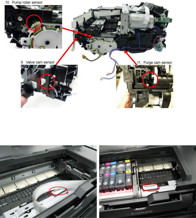
1-5. Serial Number Location
On the inner guide over the upper portion of the spur holder (visible when the scanning unit (cover) is opened)
When the machine power is OFF. |
When the machine power is ON. |
 <1. MAINTENANCE>

6 / 64

MP560 |
TABLE OF CONTENTS |
|
|
2. LIST OF ERROR DISPLAY / TROUBLESHOOTING
Errors and warnings are displayed by the following ways:
1.Operator call errors are indicated by the Alarm LED lit in orange, and the error messages are displayed by the MP driver Status Monitor.
2.Error codes (the latest 10 error codes at the maximum) are printed in the "operator call/service call error record" area in EEPROM information print
Buttons valid when an operator call error occurs:
1.ON button: To turn the machine off and on again.
2.OK button: To clear and recover from an error. In some operator call errors, the error will automatically be cleared when the cause of the error is eliminated, and pressing the OK button may not be necessary.
3.Stop button: To cancel the job at error occurrence, and to clear the error.
2-1. Operator Call Errors (by Alarm LED Lit in Orange)
Error
No paper in the rear tray.
No paper in the cassette.
Paper jam.
Paper jam in the rear guide.
Paper jam in the under guide.
Paper size not supported for automatic duplex printing (MP560 / MP568 only)
Error |
U |
Message on the |
code |
No. |
LCD |
[1000] |
--- |
Rear tray. |
|
|
There is no paper. |
|
|
Load paper and |
|
|
press [OK]. |
[1003] --- Cassette.
There is no paper. Load paper and press [OK].
[1300] |
--- The paper is |
||
[1303] |
--- |
jammed. Clear the |
|
paper and press |
|||
|
|
||
[1304] |
--- |
[OK]. |
|
|
|||
[1310] |
--- This paper is not |
||
|
|
compatible with |
|
|
|
duplex printing. |
|
Remove the paper and press [OK].
Solution
Confirm that the rear tray is selected as the paper source. Set the paper in the rear tray, and press the OK button.
Parts that are likely to be faulty
-ASF unit
-Pressure roller unit
-PE sensor board unit
Confirm that the |
- Pick-up arm unit |
cassette is selected as |
- Pressure roller unit |
the paper source. Set |
- Cassette unit |
the paper in the |
|
cassette, and press the |
|
OK button. |
|
Note that the cassette is |
|
for plain paper only. |
|
Remove the jammed |
- Pick-up arm unit |
paper and press the OK |
- ASF unit |
button. |
- Pressure roller unit |
|
- Cassette unit |
|
- Rear guide unit |
Set paper with a supported size and press the OK button.
Data which was to be printed on the back side
7 / 64
Ink may have run |
[1600] U041 The following ink |
out. |
may have run out. |
|
Replacing the ink |
|
tank is |
|
recommended. |
of paper at error occurrence is skipped (not printed).
Replace the applicable - Spur unit ink tank, or press the
Stop button to clear the error without ink tank replacement. When the error is cleared by pressing the Stop button, ink may run out during printing.
Ink tank not |
[1660] |
U043 |
The following ink |
installed. |
|
|
tank cannot be |
|
|
|
recognized. |
|
|
|
(Applicable ink tank |
|
|
|
icon) |
Print head not |
[1401] |
U051 |
Print head is not |
installed, or not |
|
|
installed. Install the |
properly installed. |
|
|
print head. |
Faulty print head |
|
U052 |
The type of print |
ID. |
|
|
head is incorrect. |
Print head |
[1403] |
|
Install the correct |
|
print head. |
||
temperature sensor |
|
|
|
|
|
|
|
error. |
|
|
|
Faulty EEPROM |
[1405] |
|
|
data of the print |
|
|
|
head. |
|
|
|
Install the applicable |
- Ink tank |
ink tank(s) properly, |
- Carriage unit |
and confirm that the |
|
LED's of all the ink |
|
tanks light red. |
|
Install the print head |
- Print head |
properly. |
- Carriage unit |
Re-set the print head. If |
- Print head |
the error is not cleared, |
- Carriage unit |
the print head may be |
|
defective. Replace the |
|
print head. |
|
Multiple ink tanks |
[1487] U071 More than one ink |
of the same color |
tank of the |
installed. |
following color is |
|
installed. |
Replace the wrong ink - Ink tank tank(s) with the correct
one(s).
Ink tank in a wrong position.
[1680] U072 Some ink tanks are not installed in place.
Install the ink tank(s) in - Ink tank the correct position.
Warning: The ink [1700] |
--- The ink absorber is |
absorber becomes |
almost full. Press |
almost full. |
[OK] to continue |
|
printing. Contact the |
|
service center for |
|
replacement. |
Replace the ink |
The ink absorber |
absorber, and reset its |
will become full |
counter. [See 4-2. |
soon (service call |
Service Mode.] |
error). |
Pressing the OK button |
|
will exit the error, and |
|
enable printing without |
|
replacing the ink |
|
absorber. However, |
|
when the ink absorber |
|
8 / 64

|
|
becomes full, no further |
|
|
printing can be |
|
|
performed unless the |
|
|
applicable ink absorber |
|
|
is replaced. |
The connected |
[2001] --- The device may be |
Remove the cable |
digital camera or |
incompatible. |
between the camera and |
digital video |
Remove the device |
the machine. |
camera does not |
and check the |
|
support Camera |
manual supplied |
|
Direct Printing. |
with the connected |
|
|
device. |
|
The remaining ink amount unknown (raw ink present).
[1683] U130 The remaining level of the following ink cannot be correctly detected. Replace the ink tank.
An ink tank which has |
- Ink tank |
once been empty is |
- Spur unit |
installed. Replace the |
|
applicable ink tank with |
|
a new one. Printing |
|
with a once-empty ink |
|
tank can damage the |
|
machine. |
|
To continue printing |
|
without replacing the |
|
ink tank(s), press the |
|
Stop button for 5 sec. or |
|
longer to disable the |
|
function to detect the |
|
remaining ink amount. |
|
After the operation, it is |
|
recorded in the machine |
|
EEPROM that the |
|
function to detect the |
|
remaining ink amount |
|
was disabled. |
|
Ink tank not |
[1684] |
U140 |
The following ink |
A non-supported ink |
- Ink tank |
recognized. |
|
|
tank cannot be |
tank (an ink tank that is |
|
|
|
|
recognized. |
sold in a different |
|
|
|
|
(Applicable ink tank |
region from where the |
|
|
|
|
icon) |
machine was |
|
|
|
|
|
purchased) is installed |
|
|
|
|
|
(the ink tank LED is |
|
|
|
|
|
turned off). Install the |
|
|
|
|
|
supported ink tanks. |
|
Ink tank not |
[1682] |
U150 |
The following ink |
A hardware error |
- Ink tank |
recognized. |
|
|
tank cannot be |
occurred in an ink tank |
|
|
|
|
recognized. |
(the ink tank LED is |
|
|
|
|
(Applicable ink tank |
turned off). Replace the |
|
|
|
|
icon) |
ink tank(s). |
|
9 / 64

No ink (no raw |
[1688] U163 The following ink |
ink). |
has run out. Replace |
|
the ink tank |
|
(Applicable ink tank |
|
icon) |
Replace the empty ink |
- Ink tank |
tank(s), and close the |
- Spur unit |
scanning unit (cover). |
|
Printing with an empty |
|
ink tank can damage the |
|
machine. |
|
To continue printing |
|
without replacing the |
|
ink tank(s), press the |
|
Stop button for 5 sec. or |
|
longer to disable the |
|
function to detect the |
|
remaining ink amount. |
|
After the operation, it is |
|
recorded in the machine |
|
that the function to |
|
detect the remaining ink |
|
amount was disabled. |
|
Non-supported |
[2002] --- An unsupported |
Remove the applicable |
hub. |
USB hub is |
USB hub from the |
|
connected. Remove |
PictBridge (USB) |
|
the hub. |
connector. |
10 / 64

2-2. Service Call Errors (by Cyclic Blinking of Alarm and Power LEDs)
Service call errors are indicated by the number of cycles the Alarm and Power LEDs blink.
Cycles of blinking of Alarm and Power LEDs
2 times
3 times
4 times
5 times
Error Error
code
Carriage error [5100]
Line feed error [6000]
Purge cam |
[5C00] |
sensor error |
|
ASF (cam) |
[5700] |
sensor error |
|
|
|
|
Solution |
Conditions |
|
|
(Check points and |
|
|
|
replacement items) |
|
|
|
|
An error occurred in the |
|
(1) Smearing or scratches on the |
|
carriage encoder signal. |
|
carriage slit film; |
|
|
|
|
clean the timing slit film. |
|
(2) |
Foreign material or paper |
|
|
|
debris that obstructs the |
|
|
|
carriage movement; |
|
|
|
|
remove foreign material. |
|
(3) |
Ink tank conditions; |
|
|
|
|
re-set the ink tanks. |
|
(4) |
Cable connection |
|
|
(5) |
Part replacement: |
|
|
|
|
- Timing slit disk film |
|
|
|
- Carriage unit |
|
|
|
- Logic board |
|
|
|
- Carriage motor |
An error occurred in the |
|
(1) Smearing or scratches on the |
|
LF encoder signal. |
|
LF / EJ slit film; |
|
|
|
|
clean the LF / EJ slit film. |
|
(2) |
Foreign material or paper |
|
|
|
debris in the LF drive; |
|
|
|
|
remove foreign material. |
|
(3) |
Cable connection |
|
|
(4) |
Part replacement: |
|
|
|
|
- LF / EJ slit film |
|
|
|
- LF / EJ timing sensor unit |
|
|
|
- Paper feed roller unit |
|
|
|
- Logic board |
|
|
|
- Paper feed motor |
An error occurred in the |
|
(1) Foreign material or paper |
|
purge unit. |
|
debris around the purge drive |
|
|
|
system unit; |
|
|
|
|
remove foreign material. |
|
(2) |
Cable connection |
|
|
(3) |
Part replacement: |
|
|
|
|
- Purge drive system unit |
|
|
|
- Logic board |
An error occurred in the |
|
(1) Cable connection |
|
ASF cam sensor (during |
|
(2) Part replacement: |
|
paper feeding from the |
|
|
- ASF unit |
rear tray). |
|
|
- PE sensor board unit |
|
|
|
- Logic board |
11 / 64

6 times |
Internal |
[5400] |
The internal temperature |
(1) |
Cable connection |
|
temperature |
|
is not normal. |
(2) |
Part replacement: |
|
error |
|
|
|
- Spur unit |
|
|
|
|
|
- Logic board |
|
|
|
|
|
- Print head |
7 times |
Ink absorber |
[5B00, |
The ink absorber is |
(1) |
Ink absorber condition |
|
full |
5B01] |
supposed to be full. |
(2) |
Part replacement: |
|
|
|
Error codes: |
|
- Ink absorber kit and |
|
|
|
5B00: Main ink |
|
double-sided adhesive |
|
|
|
absorber is full |
|
tape |
|
|
|
(overseas). |
(3) |
Ink absorber counter value in |
|
|
|
5B01: Main ink |
the EEPROM; |
|
|
|
|
absorber is full |
|
reset the ink absorber |
|
|
|
(Japan). |
|
counter. |
8 times |
Print head |
[5200] |
The print head |
(1) |
Print head condition |
|
temperature |
|
temperature exceeded |
(2) |
Head contact pin condition of |
|
rise error |
|
the specified value. |
the carriage unit |
|
|
|
|
|
(2) |
Cable connection |
|
|
|
|
(3) |
Part replacement: |
|
|
|
|
|
- Print head |
|
|
|
|
|
- Carriage unit |
9 times |
EEPROM |
[6800, |
A problem occurred in |
(1) |
Part replacement: |
|
error |
6801] |
reading from or writing |
|
- Logic board |
|
|
|
to the EEPROM. |
|
|
10 times |
VH monitor |
[B200] |
The internal temperature |
(1) |
Head contact pin condition of |
|
error |
|
exceeded the specified |
the carriage unit |
|
|
|
|
value. |
(2) |
Cable connection (especially |
|
|
|
|
the carriage FFC) |
|
|
|
|
|
(3) |
Part replacement: |
|
|
|
|
|
- Print head and logic |
|
|
|
|
|
board (Replace them at |
|
|
|
|
|
the same time.) |
|
|
|
|
|
- Power supply unit |
|
|
|
|
|
- Carriage unit |
11 times |
Carriage lift |
[5110] |
The carriage did not |
(1) |
Foreign material or paper |
|
mechanism |
|
move up or down |
debris that obstructs the |
|
|
error |
|
properly. |
carriage movement; |
|
|
|
|
|
|
remove foreign material. |
|
|
|
|
(2) |
Part replacement: |
|
|
|
|
|
- Switch system unit |
|
|
|
|
|
- Carriage unit |
12 times |
APP position |
[6A80] |
An error occurred in the |
(1) |
Foreign material or paper |
|
error |
|
APP motor. |
debris around the purge drive |
|
|
|
|
|
system unit; |
|
remove foreign material, and
confirm that the ink
12 / 64

14 times |
APP sensor |
[6A90] |
An error occurred during |
|
absorber right beneath the |
|
error |
|
paper feeding or |
|
purge drive system unit |
|
|
|
purging. |
|
stays in place and does not |
|
|
|
|
|
contact the unit. |
|
|
|
|
(2) |
Foreign material or paper |
|
|
|
|
debris around the ASF unit; |
|
|
|
|
|
|
remove foreign material. |
|
|
|
|
(3) |
Cable connection |
|
|
|
|
(4) |
Part replacement: |
|
|
|
|
|
- Purge drive system unit |
|
|
|
|
|
- Logic board |
15 times |
USB host |
[9000] |
The USB host Vbus |
(1) Part replacement: |
|
|
Vbus |
|
overloaded. |
|
- Logic board |
|
overcurrent |
|
|
|
|
16 times |
Pump roller |
[5C20] |
The pump roller position |
(1) Cable connection |
|
|
sensor error |
|
cannot be detected. |
(2) Part replacement: |
|
|
|
|
|
|
- Purge drive system unit |
19 times |
Ink tank |
[6502] |
None of the ink tank |
(1) Ink tank position; |
|
|
position sensor |
|
position is detected. |
|
confirm the ink tank |
|
error |
|
|
|
position. |
|
|
|
|
(2) |
Re-set or replacement of ink |
|
|
|
|
tanks |
|
|
|
|
|
(3) |
Cable connection |
|
|
|
|
(4) |
Part replacement: |
|
|
|
|
|
- Spur unit |
|
|
|
|
|
- Logic board |
20 times |
Other errors |
[6500] |
An unidentified error or |
(1) Part replacement: |
|
|
|
|
a network error |
|
- Logic board |
|
|
|
occurred. |
|
|
21 times |
Drive switch |
[C000] |
Drive was not switched |
(1) Foreign material or paper |
|
|
error |
|
properly. |
debris in the drive switch area; |
|
|
|
|
|
|
remove foreign material. |
|
|
|
|
(2) |
Ink tank conditions; |
|
|
|
|
|
confirm that the ink tanks |
|
|
|
|
|
are seated properly, or re- |
|
|
|
|
|
set the ink tanks properly. |
|
|
|
|
(3) |
Part replacement: |
|
|
|
|
|
- Purge drive system unit |
|
|
|
|
|
- ASF unit |
|
|
|
|
|
- Carriage unit |
22 times |
Scanner error |
[5011] |
An error occurred in the |
(1) Document pressure sheet |
|
|
|
|
scanner. |
conditions |
|
|
|
|
|
(2) |
Cable connection |
|
|
|
|
(3) |
Part replacement: |
|
|
|
|
|
- Document pressure sheet |
|
|
|
|
|
- Scanner unit |
|
|
|
|
|
- Logic board |
13 / 64
23 times |
Valve cam |
[6C10] The valve cam sensor |
(1) |
Foreign material or paper |
|
sensor error |
was faulty at power-on |
debris around the purge drive |
|
|
|
or when purging was |
system unit; |
|
|
|
attempted. |
|
remove foreign material. |
|
|
|
(2) |
Cable connection |
|
|
|
(3) |
Part replacement: |
|
|
|
|
- Purge drive system unit |
|
|
|
|
- Logic board |
Before replacement of the logic board ass'y, check the ink absorber counter value (by service test print or EEPROM information print). If the counter value is 7% or more, also replace the ink absorber kit when replacing the logic board ass'y. If the counter value is less than 7%, register the current ink absorber counter value to the replaced new logic board instead. [See 4-2. Service Mode, for details.]
14 / 64

2-3. Troubleshooting by Symptom
|
|
Symptom |
|
Solution |
Faulty operation |
The power does not turn on. |
|
The power turns off |
|
immediately after power-on. |
A strange noise occurs.
(1)Confirm connection of the power supply unit:
-Harness and connector conditions
(2)Replace the following item(s):
-Logic board
-Power supply unit
(1)Examine and remove any foreign material or paper debris.
(2)Replace the following item(s):
-The part generating the strange noise
-Logic board
The LCD does not display |
(1) |
Confirm cable connection (LCD FFC |
properly. |
and panel harness): |
|
A portion of the LCD is not |
- Harness and connector conditions |
|
displayed. |
- No cable breakage, etc. |
|
The display flickers. |
(2) |
Replace the following item(s): |
-LCD FFC
-LCD unit
-Panel board
-Logic board
Paper feed problems (multifeeding, skewed feeding, no feeding).
(1)Examine and remove any foreign material or paper debris.
(2)Confirm that the paper is supported and that the paper guides are set properly.
(3)Confirm the PF rear cover and the cassette conditions.
(4)Confirm cable connection.
(5)Replace the following item(s):
-ASF unit (for paper feeding error from the rear tray)
-PF pick-up unit (for paper feeding error from the cassette)
-PE sensor board
-Pressure roller unit
-Cassette unit
Faulty scanning (no |
(1) |
Confirm cable connection (scanner |
scanning, strange noise). |
motor cable and CIS FFC): |
|
|
- Harness and connector conditions |
|
|
- No cable breakage, etc. |
|
|
(2) |
Confirm the conditions of the inside of |
|
the platen glass: |
|
|
- FCC damper condition, etc. |
|
|
(3) |
Replace the following item(s): |
|
- Scanner unit |
|
15 / 64

|
- Logic board |
|
Machine not recognized by |
(1) Confirm USB cable connection. |
|
a USB-connected PC |
(2) Connect the machine to another PC to |
|
|
see if the machine is recognized. |
|
|
(3) |
Replace the following item(s): |
|
- USB cable |
|
|
- Logic board |
|
Unsatisfactory print quality No printing, or no color |
(1) Confirm the ink tank conditions: |
|
ejected. |
- Confirmation of the air-through of an |
|
Faint printing, or white lines |
|
ink tank |
on printouts. |
- Re-setting of an ink tank |
|
Uneven printing. |
(2) Remove foreign material from the purge |
|
Improper color hue. |
unit caps, if any. |
|
|
(3) |
Confirm the head contact pin condition |
|
of the carriage unit. |
|
|
(4) |
Perform cleaning or deep cleaning of the |
|
print head. |
|
|
(5) |
Perform print head alignment. |
|
(6) |
Replace the following item(s): |
|
- Print head*1, and ink tanks |
|
|
- Logic board |
|
|
- Purge drive system unit |
|
|
- Carriage unit |
|
Paper gets smeared. |
(1) Clean the inside of the machine. |
|
|
(2) |
Perform bottom plate cleaning. |
|
(3) |
Perform paper feed roller cleaning. |
|
(4) |
Replace the following item(s): |
|
- Pressure roller unit (if smearing is |
|
|
|
heavy) |
|
- Print head*1 (when smearing is caused |
|
|
|
by the print head) |
The back side of paper gets |
(1) Clean the inside of the machine. |
|
smeared. |
(2) Perform bottom plate cleaning. |
|
|
(3) |
Examine the platen ink absorber. |
|
(4) |
Examine the paper eject roller. |
|
(5) |
Replace the following item(s): |
|
- The part in the paper path causing the |
|
|
|
smearing |
Graphic or text is enlarged on printouts in the carriage movement direction.
(1)Confirm that the carriage slit film is free from smearing or scratches:
-Cleaning of the timing slit film.
(2)Replace the following item(s):
-Timing slit film
-Carriage unit
-Logic board
-Scanner unit (for copying)
Graphic or text is enlarged  (1) Confirm that the LF slit film is free from
16 / 64

|
on printouts in the paper |
smearing or scratches: |
|
feed direction. |
- Cleaning of the LF slit film.. |
|
|
(2) Replace the following item(s): |
|
|
- LF slit film |
|
|
- LF timing sensor unit |
|
|
- Platen unit |
|
|
- Logic board |
|
|
- Scanner unit (for copying) |
Faulty scanning |
No scanning. |
(1) Replace the following item(s): |
|
|
- Scanner unit |
|
|
- Logic board |
|
Streaks or smears on the |
(1) Clean the platen glass and the document |
|
scanned image. |
pressure sheet. |
|
|
(2) Confirm the position of the document |
|
|
pressure sheet. |
|
|
(3) Replace the following item(s): |
|
|
- Scanner unit |
|
|
- Document pressure sheet |
|
|
- Logic board |
Network connection problem No printing.
(1)Examine if printing is performed properly via USB connection.
(2)Confirm the network settings.
(3)Replace the following item(s):
-Logic board (for wireless LAN*2)
-WLAN board (for wireless LAN*2)
*1: Replace the print head only after the print head deep cleaning is performed 2 times, and when the problem persists.
*2: For the MP560 only.
 <2. LIST OF ERROR DISPLAY / INDICATION>

17 / 64
MP550/MP558, MP560/MP568 |
TABLE OF CONTENTS |
|
|
3. REPAIR
3-1. Major Replacement Parts (and Notes on Disassembling / Reassembling)
Service
part
Logic board ass'y
Absorber kit
Carriage unit
Est. time |
|
Recommended removal |
|
|
Adjustment / |
|
|
|
required |
|
procedure*1 / Notes on |
|
|
|
Operation check |
||
(min.) |
|
|
replacement*2 |
|
|
settings |
|
|
|
|
|
|
|
|
|
||
15 |
(1) |
Cassette unit |
|
After replacement: |
|
- EEPROM |
||
|
(2) |
Operation panel cover / |
1. |
Initialize the |
|
information print |
||
|
|
Right guide |
|
|
EEPROM. |
|
- Service test print |
|
|
(3) |
Right cover (2 screws) |
2. |
Set the ink absorber |
|
- Printing via USB |
||
|
(4) |
Operation panel unit (7 |
|
|
counter value. |
|
connection |
|
|
|
screws) |
3. |
Set the destination in |
|
- Copying |
||
|
(5) |
Left cover (2 screws) |
|
|
the EEPROM. |
|
- Direct printing from |
|
|
(6) |
Document cover / |
4. |
Correct the automatic |
|
a digital camera |
||
|
|
Scanning unit |
|
|
print head alignment |
|
(PictBridge) |
|
|
(7) |
Main case (3 screws) |
|
|
sensors. |
|
|
|
|
(8) |
Sub-case |
|
|
|
|
|
|
|
(9) |
Logic board (4 screws) |
5. |
Check the ink system |
|
|
||
|
|
|
|
|
|
function. |
|
|
|
|
- Before removal of the logic |
6. |
Perform LF / Eject |
|
|
||
|
|
board ass'y, remove the |
|
|
correction (only |
|
|
|
|
|
power cord, and allow for |
|
|
when streaks or |
|
|
|
|
|
approx. 1 minute (for |
|
|
uneven printing |
|
|
|
|
|
discharge of capacitor's |
|
|
occurs). |
|
|
|
|
|
accumulated charges), to |
|
|
Perform 1 to 6 in the |
|
|
|
|
|
prevent damages to the |
|
|
service mode. |
|
|
|
|
|
logic board ass'y. |
|
|
[See 4-2. Service |
|
|
|
|
|
- Before replacement, check |
|
|
Mode, for details.] |
|
|
|
|
|
the ink absorber counter |
7. |
Perform print head |
|
|
||
|
|
value (by service test print |
|
|
alignment in the user |
|
|
|
|
|
or EEPROM information |
|
|
mode. |
|
|
|
|
|
print). |
|
|
|
|
|
|
15 |
|
(1) to (8) Same as the logic |
|
After replacement: |
|
- Ink absorber counter |
||
|
|
board ass'y |
1. |
Reset the ink |
|
value print (After the |
||
|
(9) |
Front door unit |
|
|
absorber counter. |
|
ink absorber counter |
|
|
(10) |
Printer unit (11 screws) |
|
|
[See 4-2. Service |
|
is reset, the counter |
|
|
(11) |
Ink absorber |
|
|
Mode, for details.] |
|
value is printed |
|
|
|
|
|
|
|
|
|
automatically.) |
|
|
- See 3-2. Part Replacement |
|
|
|
|
|
|
|
|
Procedures, (11) Ink |
|
|
|
|
|
|
|
|
absorber replacement, for |
|
|
|
|
|
|
|
|
details. |
|
|
|
|
|
|
15 |
|
(1) to (8) Same as the logic |
|
At replacement: |
|
- Service test print |
||
|
|
board ass'y |
1. |
Apply grease to the |
|
|
||
|
(9) |
Carriage cable cover |
|
|
sliding portions of |
|
|
|
18 / 64

Switch system unit
Paper feed motor
(10)Timing slit strap
(11)Carriage rail
(12)Carriage unit
-Before removal of the carriage rail, put a mark of the carriage rail position.
-Keep the timing slit strap (carriage encoder film) free from stain or damage. When returning the strap, make sure of its orientation (left and right, front and back).
-See 3-2. Part Replacement Procedures, (7) Carriage unit removal, for details.
the carriage rail. |
value, automatic print |
[See 4-3. Grease |
head alignment |
Application, for |
sensor value, and ink |
details.] |
system function.) |
2.Check the ink system function. [See 4-2. Service Mode, for details.]
3.Perform print head alignment in the user mode.
25 |
(1) to (9) Same as the logic |
At replacement: |
- EEPROM |
|
|
board ass'y |
1. Adjust the paper feed |
information print |
|
|
(10) |
Front door link (2 |
motor. |
- Service test print |
|
screws) |
[See 4-4. Special |
|
|
|
(11) |
PictBridge board (2 |
Notes on Servicing, |
|
|
screws) |
(2) Paper feed motor |
|
|
|
(12) |
Bottom case unit (7 |
adjustment, for |
|
|
screws) |
details.] |
|
|
(13)Right chassis (3 screws)
(14)PE sensor board
(15)ASF unit (3 screws)
(16)Carriage rail
(17)Carriage unit (3 screws)
(18)Spur unit
(19)Platen unit (3 screws)
(20)LF controller unit
(21)Switch system unit / Paper feed motor
-The screws securing the paper feed motor are allowed to be loosened only for paper feed motor replacement. (DO NOT loosen them in any other cases.)
-See 3-2. Pars Replacement Procedures, (9) Purge drive system unit (right plate) and switch system unit (left
19 / 64

plate) removal, for details.
-See 3-2. Pars Replacement Procedures, (10) Engine unit reassembly, for details.
Platen unit |
25 |
(1) to (9) Same as the logic |
After replacement: |
- EEPROM |
|
|
|
board ass'y |
1. Perform LF / Eject |
information print |
|
|
|
(10) |
Front door link (2 |
correction in the |
- Service test print |
|
|
screws) |
service mode (only |
|
|
|
|
(11) |
PictBridge board (2 |
when uneven printing |
|
|
|
screws) |
or streaks appear on |
|
|
|
|
(12) |
Bottom case unit (7 |
printouts after |
|
|
|
screws) |
replacement). |
|
|
|
|
(13) |
Right chassis (3 |
[See 4-2. Service |
|
|
|
screws) |
Mode, for details.] |
|
|
(14)PE sensor board
(15)ASF unit (3 screws)
(16)Carriage rail
(17)Carriage unit (3 screws)
(18)Spur unit
(19)Platen unit (3 screws)
Spur unit |
25 |
(1) to (9) Same as the logic |
After replacement: |
- EEPROM |
|
|
|
board ass'y |
1. Check the ink system |
information print |
|
|
|
(10) |
Front door link (2 |
function. |
- Service test print |
|
|
screws) |
2. Perform LF / Eject |
|
|
|
|
(11) |
PictBridge board (2 |
correction in the |
|
|
|
screws) |
service mode (only |
|
|
|
|
(12) |
Bottom case unit (7 |
when uneven printing |
|
|
|
screws) |
or streaks appear on |
|
|
|
|
(13) |
Right chassis (3 |
printouts after |
|
|
|
screws) |
replacement). |
|
|
|
|
(14) |
PE sensor board |
[See 4-2. Service |
|
|
|
(15) |
ASF unit (3 screws) |
Mode, for details.] |
|
|
|
(16) |
Carriage rail |
|
|
|
|
(17) |
Carriage unit (3 screws) |
|
|
|
|
(18) |
Spur unit |
|
|
|
|
- DO NOT contact the spur |
|
|
|
|
|
edges. |
|
|
|
Purge drive |
25 |
(1) to (20) Same as the |
After replacement: |
- Service test print |
|
system unit |
|
switch system unit and the |
1. Confirm the purging |
|
|
|
|
paper feed motor |
operation and the |
|
|
|
|
(21) |
Purge drive system unit |
machine operation. |
|
|
|
|
|
[See 4-5. Verification |
|
|
|
- See 3-2. Pars Replacement |
After Repair for |
|
|
|
|
Procedures, (9) Purge drive |
details.] |
|
|
|
|
system unit (right plate) |
|
|
|
and switch system unit (left plate) removal, for details.
20 / 64
Loading...