


 Loading...
Printed by Canon Inc.
Mar. 2007 Rev.05a
CXDI-1 System
CXDI-50G / 50C
Service Manual
Canon Inc. Japan
Copyright (C) Canon Inc. Medical Technical Service Dept. All rights Reserved.
Manual Control No. |
: BY8-2257-0E5 |
Name of Product |
: CXDI-50G/50C |
Distribution Control No. |
|
Issued on |
|
Service Manual Introduction
This service manual belongs to a series of after-service guides Canon Inc. publishes as part of its comprehensive product quality guarantee program.
This service manual consists of seven chapters; General Information, Installation Guide, Feature Information, Repair Guide, Parts Catalog, Troubleshooting and Service Manual Report.
If the product undergoes a large modification, a new service manual of revised edition will be sent to you. In other cases, service manual report will be sent to you updates the manual.
Note 1:
This service manual is published by Canon Inc. in accordance with Article 6 (Furnishing the Referent Materials) of the Service Assignment Contract it has concluded with your company.
Note 2:
This service manual property of Canon Inc. and the company may seek to have it returned, depending on circumstances. You are expected to keep it until then.
Note 3:
You inquiries, suggestions etc. about the contents of this service manual should be addressed to:
Medical Products Technical Service Dept.
Canon Inc. Headquarters
30-2, Shimomaruko 3-chome, Ohta-ku, Tokyo 146-8501, Japan
Caution Regarding Service
This product was precisely assembled under strict manufacturing process control. There are several hazardous locations inside of this product. Careless work while the cover is removed can result in pinching fingers or cause electrical shock. Please perform the work with the following important points in mind:
1.Setup, Repair and Maintenance
In order to ensure safety, the best performance, setup, repair and maintenance work can only be performed by the technicians received the service training specified by Canon Inc. If there are order required certificates or restrictions specified by the law or ordinances, those regulations of the country must be observed.
2.Removing the external cover
When removing the cover during maintenance, repair, etc., perform the work after switching the power off. Never touch the device with wet hands, as there is a risk of electric shock.
3.Fuse
When replacing the fuse, first, resolve the reason of failure and then replace the fuse with the specified type. Never use a fuse other than the specified type.
4.Connecting the grounding wire
The provided ground wire must be connected to the ground terminal indoors. make sure that the device is properly grounded.
5.Alternation prohibition
Never modify the medical device in any way.
6.Waste control
The service provider is responsible for the disposal of used service parts, packing material, etc. resulting from the setup, repair or maintenance of the medical device However, the customer is responsible for the disposal of the medical device. Disposal activities must follow the regulations (=specially controlled industrial waste) of the country where the device is used.
VORSICHT
Befolgen Sie die unten angegebenen Sicherheitsanweisungen.
Mißachtung kann zu erletzungenoder Unfällen führen.
1.Zerlegung, Zusammenbau, Einstellung und Wartung
Zerlegung, Zusammenbau, Einstellung und Wartung dürfen nur von einem Wartungstechniker durchgeführt werden, der an einem von Canon vorgeschriebenen Wartungslehrgang teilgenommen hat.
2.Entfernen von Abdeckungen
Schalten Sie unbedingt die Stromversorgung des Instruments aus, bevor Sie die Abdeckungen zwecks Wartung und Reparatur entfernen.
Vermeiden Sie auch eine Berührung des Instruments mit nassen Händen.
Anderenfalls können Sie einen elektrischen Schlag erleiden, der zum Tod oder schwerer Verletzung führen kann.
3.Sicherung
Wenn die Sicherung ausgewechselt werden muß, schalten Sie unbedingt die Stromversorgung des Instruments aus, und beheben Sie die Ursache für das Durchbrennen der Sicherung.
Ersetzen Sie die Sicherung nur durch den vorgeschriebenen Typ. Anderenfalls kann es zu einem Brand oder elektrischen Schlag kommen.
4.Erdleiter
Erden Sie das Instrument unbedingt an einer Schukosteckdose.
Anderenfalls kann es zu einem Brand oder elektrischen Schlag durch Leckstrom kommen.
5.Umbau
Jeder Umbau des Produktes ist strengstens untersagt, da dies zu einem Brand oder elektrischen Schlag führen kann.
6.Bewegliche Teile
Dieses Instrument enthält bewegliche Teile.
Führen Sie während der Bewegung der Teile keine unachtsame Tätigkeit aus. Anderenfalls können Sie verletzt werden.
7.Schnittstellenanschluß
Wenn andere Geräte über den Schnittstellenanschluß an das Instrument angeschlossen werden, prüfen Sie nach dem Anschluß, daß der Leckstrom innerhalb des zulässigen
Bereichs liegt.
8.Lithiumbatterie
Ersetzen Sie die Lithiumbatterie nur durch den vorgeschriebenen Typ.
Verbrauchte Batterien dürfen nicht ins Feuer geworfen und weder zerlegt noch geladen werden. Entsorgen Sie verbrauchte Batterien umweltschonend gemäß den Gesetzen
oder Vorschriften des Landes, in dem das Instrument benutzt wird.

Caution regarding the setup
According to the “IEC60601-1-1:2000”, devices installed in the patient environment are restricted to “electric medical devices conforming to IEC60601-1”.
The Control PC, operation unit, and the magnetic card reader, etc. options that are parts of the CXDI-C3S are classified under the data processing device standard (IEC60950), therefore these items should not be installed in the patient environment. Otherwise the Control PC is only classified in CXDI-C3S.
The patient environment described below is an example cited from the “IEC60601-1-1:2000” – the measurements are only guidelines. However, the “IEC60601-1-1:2000” example must be treated as the standard.
Therefore, the CXDI-C3S must be installed in a location further than the measurements below (outside of the patient environment).
*Areas where the patient moves (not only during imaging but when entering and leaving the room, etc.) are also considered as part of the patient environment, therefore the installation location should be determined upon consultation with the user regarding areas outside of the patient environment.
Example of patient environment
Note: The measurements are only guidelines.

Printed by Canon Inc.
Feb. 2006 Rev.03
CXDI-50G / 50C
1. General
Canon Inc. Japan
Copyright (C) Canon Inc. Medical Technical Service Dept. All rights
Reserved.
|
|
Content |
|
General ................................................................................................................................................ |
1 |
1 |
CXDI-1 System Block Diagram .......................................................................................................... |
2 |
2 |
System Diagram................................................................................................................................... |
3 |
3 |
CXDI Image Processing....................................................................................................................... |
4 |
4 |
Specifications....................................................................................................................................... |
5 |
1. General
General
CXDI-50G
Change of the image read-out method from the sensor was made to the former CXDI-50G. In the former CXDI-50G, Aux. Shift Register Driver (PCB-D-EP), Scanner with Main Scanner Driver (PCB-50A) and A/D Conversion (PCB-50AD) are located in the both sides of LANMIT. One panel is considered as two virtual panels, and image data was read out from both sides. However, in new CXDI-50G, Aux. Shift Register Driver (PCB-D-EP), Signal Read-out Circuit (PCB-50A) and the A/D Conversion (PCB-50AD) are located in one side of LANMIT and the image data was read from one side. Since the appearance of new CXDI-50G is the same as that of the former CXDI-50G, they are identified by changing the serial number of the main unit.
CXDI System Software |
Ver.6.4 and later |
|
|
|
|
Clinic Software |
Ver.1.04 and later |
|
|
|
|
Serial number of main units |
7M 150001~ |
|
3M 250001~ |
||
|
CXDI-50C
Fluorescent substance of CXDI-50G has been changed to CsI from GOS in CXDI-50C so that the CXDI-50C can be ranked as the more superior performance model (high sensitivity model) than CXDI-50G. The read-out method of image data is read-out from both sides of LANMIT which is same as CXDI-50G.
|
Ver.6.4 and later |
CXDI System Software |
7M 100001~ |
|
3M 200001~ |
1

1. General
1 CXDI-1 System Block Diagram
|
|
|
|
|
|
|
|
|
|
|
|
Remo. |
|
|
|
|
|
|
|
|||||||
|
|
|
|
|
|
|
|
|
|
|
|
|
|
|
|
|
|
|
|
|
|
|
|
|
|
|
|
|
|
|
|
|
|
|
|
|
|
|
|
|
|
|
|
|
|
|
|
|
|
|
|
|
|
|
|
|
|
|
|
|
|
Power Box |
|
|
|
|
|
|
|
|
|
|
|
|
|
|
|
|
|
|
|
|
|
|
|
|
|
|
|
|
|
Imaging Unit |
|
|
|
|
|
|
|
|
|
|
|
|
|
|
|
|
CA1 |
|
|
|
|
|
SPW |
|
|
|
|
|
|
|
|
|
|
|
|
|
|
|
||||
|
|
|
|
|
|
(CXDI-50G/50C) |
|
|
|
|
|
|
|
|
|
|
|
|
||||||||
AC120V/230V |
|
|
AC Power IN |
|
CA2 |
|
|
|
|
|
|
|
|
|
|
|
|
|
||||||||
|
|
|
|
|
|
|
|
|
||||||||||||||||||
|
|
|
|
|
|
|
|
OUT PUT 1 |
|
|
|
Control/Signal |
|
|
|
|
|
|
|
|
|
|
|
|
||
|
|
|
|
|
|
|
|
Control/Signal |
|
|
|
|
|
|
|
|
|
|
|
|
|
|
|
|
|
|
|
|
|
|
|
|
|
|
|
|
|
|
|
|
|
|
|
|
|
|
|
|
|
|
|
|
|
|
|
|
X-Ray |
OUT PUT 2 |
|
|
|
|
|
|
|
|
|
|
|
CA6 |
|
|
|
|
|
|
||||
|
|
|
|
|
|
|
|
|
|
|
|
|
|
|
|
|
|
|
Operation |
|||||||
|
|
|
|
|
|
|
|
|
|
|
|
|
|
|
|
|
|
|
||||||||
|
|
|
|
|
I/F |
Control/Signal |
|
|
|
|
|
|
SERIAL(COM1) |
|
|
|
|
|
|
|
|
RS232C |
||||
|
|
|
|
|
|
|
|
|
|
|
|
|
|
|
|
|
|
|
||||||||
|
|
|
|
|
|
|
|
|
|
|
|
|
|
|
|
|
|
|
|
|
|
|
|
|
|
Unit |
|
|
|
|
|
|
|
|
|
|
|
|
|
|
|
|
|
|
|
|
|
|
|
|
|
|
|
CA3 |
Control PC |
|
CA7 |
(CXDI-C3S) |
VGA |
VGA |
|
|
|
|
|
|
CA4 |
|
|
|
|
|
|
|
SERIAL(COM2) |
|
|
|
|
RS232C |
ID Unit |
||||
|
|
|
|
|
|
|
|
|
|
|
|
|
LAN1 |
|
|
|
|
|||||||
|
|
|
|
|
|
|
|
|
|
|
|
|
|
|
|
|
|
|
|
|
|
(Option) |
||
|
|
X-Ray Generator |
|
|
|
|
|
|
|
|
|
|
|
|
|
|
|
|
|
|
|
|||
|
|
|
|
|
|
|
|
|
|
|
|
|
|
|
|
|
|
|
|
|||||
|
|
|
|
|
|
|
|
CA5 |
|
MOUSE |
|
|
|
|
Mouse |
|
||||||||
|
|
|
|
|
|
|
|
|
|
|
|
|
|
|||||||||||
|
|
|
|
|
|
|
|
|
|
|
|
|
|
|
|
|
|
|
|
|
|
|||
|
|
|
|
|
|
|
|
|
|
|
|
|
|
|
|
|
|
|
|
|
||||
|
|
|
|
|
|
|
|
|
|
|
|
|
LAN2 |
KEY BOARD |
|
|
|
|
Key Board |
|
||||
|
|
|
|
|
|
|
|
|
|
|
|
|
|
|
|
|
|
|
||||||
|
|
|
|
|
|
|
|
|
|
|
|
|
|
|
|
SCSI |
|
|
|
|
|
|
|
|
|
|
|
|
|
|
|
|
|
|
|
|
|
|
|
|
|
|
|
|
|
|
|
||
|
|
|
|
|
|
|
|
|
|
|
|
|
|
|
|
|
|
|
|
|
|
|
||
|
|
|
|
|
|
|
|
|
|
|
|
|
|
|
|
|
|
|
|
|
|
|
||
|
|
|
|
|
|
|
|
|
|
|
|
|
|
|
|
|
|
|
|
|
|
|
||
|
|
|
|
|
|
|
|
|
|
|
|
|
|
|
|
|
|
|
|
|
||||
|
|
|
|
|
|
Printer |
|
|
|
|
|
|
|
SERIAL(COM3) |
|
|
|
|
|
|
||||
|
|
|
|
|
|
|
|
|
|
|
|
|
|
|
|
|
|
|||||||
|
|
|
|
|
|
|
|
|
|
|
|
|
|
|
|
|
|
|
||||||
|
|
|
|
|
|
Image diagnosis |
|
|
|
|
|
|
|
SERIAL(COM4) |
|
|
|
|
|
|
||||
|
|
|
|
|
|
|
|
|
|
|
|
|
|
|
|
|
|
|||||||
|
|
|
|
|
|
|
|
|
|
|
|
|
|
|
|
|
|
|
|
|||||
|
|
|
|
|
|
|
|
|
|
|
|
|
AC Power IN |
|
|
|
|
|||||||
|
|
|
|
|
|
|
|
|
|
|
|
|
|
|
|
|||||||||
|
|
|
|
|
|
|
|
|
|
|
|
|
|
|
|
|||||||||
|
|
|
|
|
|
W/S |
|
|
|
|
|
|
|
|
|
|
|
|
|
|
|
|
|
|
|
|
|
|
|
|
|
|
|
|
|
|
|
|
|
|
|
|
|
|
|
|
|
||
|
|
|
|
|
|
|
|
|
|
|
|
|
|
CA8 |
|
|
|
|
||||||
|
|
|
|
|
|
|
|
|
|
|
|
|
|
|
|
|
|
|
|
|||||
|
|
|
|
|
|
Image file device |
|
|
|
|
|
|
|
|
|
|
|
|
|
|
|
|
|
|
|
|
|
|
|
|
|
|
|
|
|
|
|
|
|
|
|
|
|
|
|
|
|
||
|
|
|
|
|
|
|
|
|
|
|
|
|
|
|
|
|
|
|
|
|
|
|||
Symbol |
Description |
Remarks |
|
|
|
|
|
|
|
AC120V±10% 60Hz 2A |
|
|
|
|
||||||||||
CA1 |
AC Cable |
3m |
|
Network |
AC230V±10% 50/60Hz 1.5A |
|
|
|
|
|||||||||||||||
CA2 |
50Sensor Cable |
3m/7m |
|
|
|
|
|
|
|
|
|
|
|
|
||||||||||
CA3 |
X-Ray I/F Cable |
20m |
|
Ethernet |
|
|
|
|
|
|
|
|
|
|
|
|||||||||
CA4 |
LAN Cable (Category 5) |
|
|
|
|
(100/10bese-T) |
|
|
|
|
|
|
|
|
|
|
|
|||||||
CA5 |
LAN Cable (Category 5) |
10m |
|
|
|
|
|
|
|
|
|
|
|
|
|
|
|
|
|
|
|
|||
CA6 |
Serial Cable (Touch Panel) |
2m |
|
|
|
|
|
|
|
|
|
|
|
|
|
|
|
|
|
|
|
|||
CA7 |
VGA Cable |
1.5m |
|
|
|
|
|
|
|
|
|
|
|
|
|
|
|
|
|
|
|
|||
CA8 |
AC Cable |
3m |
|
|
|
|
|
|
|
|
|
|
|
|
|
|
|
|
|
|
|
|||
2

1. General
2 System Diagram
2.1 Standalone System
CXDI-50G/50C
2.2 Total System
Total System Block Diagram (Example)
Patient Circumstances or Medical Room
|
|
|
|
|
|
|
|
|
|
|
|
|
|
|
|
|
|
|
|
|
|
|
|
|
|
|
|
|
|
|
|
|
|
|
|
|
|
|
|
|
|
|
|
|
|
|
|
|
|
|
|
|
|
|
|
|
|
|
|
|
|
|
|
|
|
|
|
|
|
|
|
|
|
|
|
|
|
|
|
|
|
|
|
|
|
|
|
|
|
|
|
|
|
|
|
|
|
|
|
|
|
|
|
|
|
|
|
|
|
|
|
|
|
|
|
|
|
|
|
|
|
|
|
|
|
|
|
|
|
|
|
|
|
|
|
|
|
|
|
|
|
|
|
|
|
|
|
|
|
|
|
|
|
|
|
|
CXDI-50G/50C |
|
|
|
Network switch |
|
|
||||
|
|
|
|
Contorol PC |
|
Multi Box 2 |
|||||
|
|
|
|
|
|
C3 |
|
||||
|
|
|
POWER BOX |
|
Ethernet |
||||||
|
|
|
|
|
50 Power |
|
|
|
|
|
|
|
|
|
|
|
Supply |
|
|
|
|
|
|
|
|
|
|
|
1st/2nd |
|
|
|
|
|
|
|
|
|
|
|
AC230V |
|
|
|
|
|
|
|
|
|
|
|
Insulation |
|
|
|
|
|
|
|
|
|
|
|
with reinforcement |
|
|
|
|
|
|
|
Protective |
|
|
|
|
|
|
|
|
|
|
|
Grounding |
|
|
|
|
|
AC230V |
|
|
||
|
|
|
|
|
|
|
|
Basic Insulation |
|
|
|
|
CXDI-40E |
|
|
|
|
|
|
Ethernet |
|
X-ray generator |
|
|
Imaging Unit |
|
Power Box |
|
|
|
|
|
(601 compatible) |
||
Ethernet
Grid
Imaging Unit
Unit
Remote switch
CXDI-40G/
CXDI-31 etc.
Imaging Unit
Image Examination WS
Image File Equipment
Printer etc.
3
1. General
3 CXDI Image Processing
3.1 Proccess Flow
|
Born image |
Offset correction |
|||
|
|
|
|
Correction |
Gain correction |
|
|
|
|
||
|
|
|
|
processing |
|
|
|
|
|
|
|
|
Raw image |
|
Defect correction |
||
|
|
|
|
|
|
|
|
|
|
|
dtstore |
|
Original image |
|
|
||
|
|
|
|
|
Characteristic extraction |
|
|
|
QA processing |
||
|
|
|
|
||
|
|
|
|
|
• Sharpening |
|
QA image |
|
|||
|
|
• DEP |
|||
|
|
|
|
|
|
|
|
|
DICOM output |
• Gradation processing |
|
|
|
|
|
|
• MTF enhancement |
|
Diag. image |
|
|||
|
|
(Frequency enhancement) |
|||
|
|
|
|
|
|
|
|
|
|
|
• Grid stripe reduction |
|
|
|
|
|
• High density clipping |
|
Processed image |
|
|||
|
|
request |
|||
|
|
|
|
|
|
3.2Image Types
(1)BORN IMAGE
The image obtained with LANMIT before any correction is made.
Outside distribution of these images is prohibited, including dtstore images.
(2)RAW IMAGE
Born image after offset processing, gain correction.
This is the image with LANMIT specific characteristics corrected.
(3)ORIGINAL IMAGE
Raw image after preprocessing.
(4)QA IMAGE
Original image after gradation processing, sharpening, and other processing. The CXDI performs image processing up to this point.
(5)DIAG. IMAGE
QA image after further image processing necessary for diagnosis. Image processed by the user for diagnostic purposes.
(6)PROCESSED IMAGE
Diagnosis image after post-processing.
Image modified by the user or the default processed image.
4
1. General
4 Specifications
The CXDI-50G/50C (Imaging Unit/Power Box) is the Digital Cassette that has the mobility and can be used on the optional angles.
(1)Imaging Unit
This unit consists of the internal sensor, 50Di Board, 50AD Board, 50LED Board and its outer cover. The sensor unit converts the X-ray image to the electrical signal (O/E Conversion) and after performs the A/D conversion, transfer its signal through the Power Box with Ethernet cable to the Control PC.
|
Item |
50G |
50C |
Remarks |
|
|
|
|
|
|
|
Object |
|
General Shooting Cassette |
Å |
(Mobile/Desktop PC) |
|
Effective filming range |
353 x 430mm |
Å |
|
||
Number of Pixels |
2214 x 2700 |
Å |
|
||
Effective Number of Pixels |
2208 x 2688 |
Å |
|
||
Pixel pitch |
|
160µm x 160µm |
Å |
|
|
Fluorescent substance |
GOS Fluorescent screen |
CsI |
one panel |
||
Output gradations |
12bit (4,096 gradations) |
Å |
|
||
A/D 14bit |
|
||||
|
|
|
|
||
Transfer method |
Ethernet: Imaging Unit to |
|
|
||
Control PC |
Å |
|
|||
|
|
(Through the Power Box) |
|
|
|
Imaging cycle |
15 sec. (standard) |
Å |
|
||
Dimension |
|
491 (W) x 477 (D) x 23 (H) |
Å |
Including handle portion |
|
|
|
mm |
427 mm (excluding handle portion) |
||
|
|
|
|||
Imaging Unit coloring |
Cool white |
Å |
|
||
Imaging Unit mass |
4.8Kg |
4.9kg |
Except the cable |
||
5.7Kg |
5.8kg |
With 7m cable |
|||
(except Grid) |
|||||
5.2Kg |
5.3kg |
With 3m cable |
|||
|
|
||||
Space between surface where |
Within 5.0±0.5mm. |
Within 4.9±0.5mm |
|
||
patient gets in contact (CFRP) |
|
||||
and sensor surface (glass) |
|
|
|
||
Heat |
Remote SW OFF |
9.5kcal/h |
Å |
Including the Power Box |
|
Sleep |
19kcal/h |
Å |
Including the Power Box |
||
emission |
Max load mode |
24kcal/h |
30kcal/h |
Including the Power Box |
|
|
1 image per 15 Sec. |
||||
|
|
|
|
||
Power |
Remote SW OFF |
11W |
Å |
Including the Power Box |
|
Sleep |
22W |
Å |
Including the Power Box |
||
Consumpt |
|||||
|
|
|
Including the Power Box |
||
-ion |
Max load mode |
28W |
35W |
||
1 image per 15 Sec. |
|||||
|
|
|
|
||
|
|
Cassette with resisting the |
|
Load uniformly: 150Kg |
|
Mechanical strength* |
|
Load partly: 100Kg/φ40mm |
|||
strength |
Å |
||||
|
|
(Original specification) |
|
The Imaging unit is put on the plain surface |
|
|
|
|
with the Sensor side (Detector) is up. |
||
|
|
|
|
||
Control PC |
|
CXDI-C3S |
Å |
|
|
|
General PC in market |
|
|||
|
|
|
|
||
Power Control |
None |
|
|
||
(Power Box: Operation |
Å |
|
|||
(ON/OFF) |
|
with Remote switch |
|
||
|
|
|
|||
|
|
manually) |
|
|
|
Grid attach/remove detector |
Yes |
Å |
|
||
Cable for Imaging Unit |
3/7m 2types |
Å |
Distinguish with Product order. |
||
|
|
Multiple Imaging Units are |
|
|
|
|
|
connectable to a single |
|
|
|
|
|
control PC via Network |
|
Network switch should be procured at each |
|
Count of connected sensor |
switch. (Limitation of the |
Å |
|||
number of connectable |
sales company. |
||||
|
|
|
|||
|
|
Imaging Unit depends on the |
|
|
|
|
|
specification of control |
|
|
|
|
|
software in control PC) |
|
|
|
Scattered radiation backward |
|
|
|
||
block sheet |
|
Mo sheet (0.3 mm thick) |
Å |
|
|
Environment-conscious |
|
||||
|
|
|
|||
unleaded type |
|
|
|
||
Photo timer |
|
Cannot be built in |
Å |
|
|
5
1. General
Item |
50G |
50C |
|
Remarks |
|
|
||
|
|
|
|
|
|
|
|
|
|
When the internal |
|
|
|
|
|
|
|
|
temperature of Imaging Unit |
|
|
|
|
|
|
|
|
is above 49 degree Celsius, |
|
|
|
|
|
|
|
Imaging restriction |
its state is changed to sleep |
|
|
|
|
|
|
|
mode. And the Imaging |
Å |
|
|
|
|
|
|
|
(Imaging Prohibition) |
|
|
|
|
|
|
||
prohibition will be continued |
|
|
|
|
|
|
|
|
|
|
|
|
|
|
|
|
|
|
when the internal |
|
|
|
|
|
|
|
|
temperature is below 48 |
|
|
|
|
|
|
|
|
degree Celsius. |
|
|
|
|
|
|
|
|
|
|
INDICATION |
BUSY |
|
SENSOR |
POWER |
|
|
|
|
Color |
Orange |
|
Green |
|
Blue |
|
|
|
Imaging unit |
Off |
|
Off |
|
Off |
|
|
|
is off |
|
|
|||
|
|
|
|
|
|
|
|
|
|
|
|
Imaging unit |
-- |
|
Off |
|
On |
|
|
|
is on |
|
|
|||
|
|
|
|
|
|
|
|
|
|
|
|
Preparing |
-- |
|
Blinking *1 |
On |
|
|
|
|
imaging |
|
|
|
|
|
|
Single type LED |
|
Imaging |
|
|
|
|
|
|
|
preparation |
-- |
|
Off |
|
On |
|
|
Off: Imaging unit power is |
|
|
|
||||
|
|
complete |
|
|
|
|
|
|
|
off |
|
|
|
|
|
|
|
|
|
Error status |
-- |
|
Blinking |
*2 |
On |
|
|
On in orange: Imaging unit |
|
|
|
||||
|
|
Communi- |
Blinking |
*3 |
-- |
|
On |
|
User interface |
power is on (unable to |
Å |
cating |
|
|
|||
perform imaging) |
Initialization |
|
|
Blinking *4 |
|
|||
|
|
|
|
|
||||
|
Blinking in green: Preparing |
|
(when |
-- |
|
On |
||
|
imaging/error status |
|
startup) |
|
|
|
|
|
|
On in green: Imaging |
|
Network not |
-- |
|
Blinking *5 |
On |
|
|
preparation is complete |
|
set (when |
|
||||
|
|
startup) |
|
|
|
|
|
|
|
|
|
|
|
|
|
|
|
|
|
|
*1: Turns on |
and off for 0.5 seconds each |
||||
|
|
|
*2: Turns on and off twice for 0.5 seconds, then |
|||||
|
|
|
turns off for 0.5 seconds |
|
|
|||
|
|
|
*3: Turns on and off randomly |
|
|
|||
|
|
|
*4: Fades in for 1 second and fades out for 1 |
|||||
|
|
|
second |
|
|
|
|
|
|
|
|
*5: Fades in for 2 seconds, and then turns off |
|||||
6

1. General
(2)Power Box
This unit consists of 40XRAY Board, 50Power Supply and its outer cover.
The function; the signal transition between Imaging unit and Control PC, the interface to the X-ray generator equipment and power supply to the Imaging unit has been implemented.
Item |
Content |
Remarks |
|
|
|
|
|
Communication |
IEEEE* 802.3u (100BASE-TX) |
Connector type: RJ45 |
|
interface standard |
|
|
|
Communication method |
Asynchronous serial communication |
Data length: 10bit |
|
method |
Data rate: 15.625 kHz |
||
|
|||
|
|
Reference |
|
|
AC 100-120V±10% 50/60Hz 1.5A |
CXDI-50G Power supply |
|
Power supply |
Rated Voltage: |
||
AC 200-240V±10% 50/60Hz 0.8A |
|||
|
AC 100-120V (AC 85-132V) |
||
|
|
||
|
|
AC 200-240V (AC170-264V) |
|
Mass |
4.2 Kg |
|
|
|
|
Except bottom rubber parts |
|
Dimension |
358(W) x 200(D) x 65(H)* mm |
(With bottom rubber parts: |
|
|
|
75mm) |
|
(3) Environment rated parameters |
|
||
|
|
|
|
Item |
Content |
Remarks |
|
|
|
|
|
Operating temperature |
+5 to +35°C |
Must be without dewing |
|
Operating humidity |
30 to 75% RH |
||
|
|||
Keeping or |
Temperature: -30 to +50°C |
|
|
Humidity: 10 to 60% RH |
|
||
Transporting |
|
||
Atmospheric pressure: 700 to 1060 hPa |
|
||
|
|
||
* IEEE: Institute of Electrical and Electronic Engineers
7

Printed by Canon Inc.
Feb. 2007 Rev.04
CXDI-50G / 50C
2. Installation Manual
Canon Inc. Japan
Copyright (C) Canon Inc. Medical Technical Service Dept. All rights
Reserved.
Content
1 |
Caution during the installation .............................................................................................. |
1 |
|
2 |
Product Configuration ........................................................................................................... |
2 |
|
3 |
Packing Diagram ................................................................................................................... |
5 |
|
4 |
Installation Procedures .......................................................................................................... |
7 |
|
|
4.1 |
Lists of Tool Needed for Installation ............................................................................. |
7 |
|
4.2 |
System Installation Procedures ...................................................................................... |
8 |
5 |
Installation ........................................................................................................................... |
10 |
|
|
5.1 |
Connection to each unit................................................................................................ |
10 |
|
5.2 |
Starting up and shutting down the System................................................................... |
16 |
|
5.3 |
X-ray Controller Interface............................................................................................ |
17 |
|
5.4 |
Network Settings 1....................................................................................................... |
23 |
|
5.5 |
Setting the Fixed ROI Areas...................................................................................................... |
26 |
|
5.6 |
Adjusting the photo timer .......................................................................................................... |
29 |
|
5.7 |
Settings......................................................................................................................... |
31 |
|
5.8 |
Adjusting the Alignment............................................................................................................ |
87 |
|
5.9 |
Image Quality............................................................................................................... |
93 |
|
5.10 |
Post-installation checks................................................................................................ |
95 |
6 |
Dimension............................................................................................................................ |
97 |
|
2. Installation Manual
1 Caution during the installation
Please pay attention to the followings when installing the system.
(1)If the equipment is hoisted, lowered or transport, it must be supported at both sides by a minimum of two people so there is no danger of it falling.
(2)If a forklift, etc. is used to transport the equipment, make sure there is nothing that could impede the forklift on its route to the final destination.
(3)When installing the equipment, be sure the site meets the following criteria:
1)There must be no dripping water in the area.
2)The environment must be free of harmful elements such as humid or acidic air, air with a saline or sulfur content, where there is poor ventilation or where air pressure or temperature is unusual.
3)The equipment must not be placed at an angle or subjected to vibration or shock (this includes during transportation).
4)The equipment must not be kept where chemical products are stored or where gasses are generated.
5)The site’s power supply must be of the correct voltage and frequency for the equipment.
6)The site must be connected to a fully earthed cable with sufficient ground resistance to meet standard values.
(4)After installation, be sure to dispose of waste product packaging with care and with full respect for the environment.
- 1 -
2. Installation Manual
2 Product Configuration
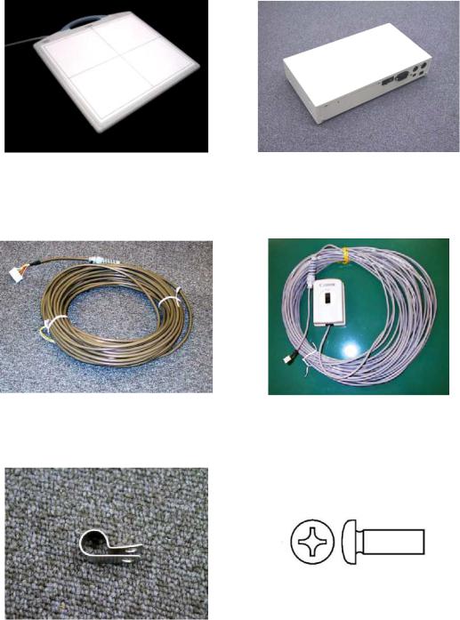
2.1 Product Configuration List
No. |
Item Name |
Qty |
Remarks |
1 |
CXDI-50G/50C Imaging Unit |
1 |
With Sensor cable (3/7m) |
2 |
Power Box |
1 |
100 - 120/230V |
3 |
X-ray I/F cable |
1 |
20m |
4 |
Remote switch |
1 |
20m |
5 |
Cable clump |
1 |
For fixing the sensor cable |
6 |
Screw (M4 x 6 mm) XB1-1400-603 |
1 |
For fixing the cable clump |
7 |
Sensor Information File (FD) |
1 |
|
8 |
Power supply cable (with AC plug) |
1 |
3m (100/120/230V) |
9 |
Attached documents for medical |
- |
(100V) |
|
Certifications |
|
|
10 |
(warranty registration, inspection |
- |
(100V) |
|
compliance, operation manual) |
|
|
11 |
Inspection compliance, operation manual |
- |
(120/230V) |
12 |
Packaging |
- |
|
LAN cable for connecting Control PC / Power Box and Network switch (Switching HUB) for connecting the multiple Imaging Units shall be procured at each sales company.
- LAN cable (Over category 5)\
When Control PC and Power Box are connected directly, Cross type is used, but when they are connected via Network switch, Straight type is used. However, this is not applied when Network switch has AUTO-MDI/MDI-X function*.
- Network switch (Switching HUB)
Sales companies adopt Network switch (Switching HUB) after conducting the test and the operation check for Switching HUB that meets the general standard.
* AUTO-MDI/MDI-X :
One of the functions of Network switch (Switching HUB) and Broadband-router.
They can detect Communication port of other side automatically and connect in proper procedure. MDI: Network-card, etc.
MDI-X: Network switch (Switching HUB) and Broadband-router, etc.
Since AUTO-MDI/AUTO-MDI-X functions can detect automatically in proper procedure, they do not require consideration to types of LAN cable (Straight of Cross cable).
- 2 -
2. Installation Manual
2.2 Configuration
No. |
1 |
No. |
2 |
|
Name |
CXDI-50G/50CImaging Unit |
Name |
Power Box |
|
Qty |
1 |
Qty |
1 |
|
Remarks |
3/7m |
Remarks |
I/F and Power supply (3/7m) |
|
|
|
|
|
|
No. |
3 |
No. |
4 |
|
Name |
X-ray I/F cable |
Name |
Remote switch |
|
Qty |
1 |
Qty |
1 |
|
Remarks |
Connection with X-ray |
Remarks |
Power Box power source |
|
generator |
ON/OFF |
|||
|
|
|||
|
|
|
|
|
No. |
5 |
No. |
6 |
|
Name |
Cable clump |
Name |
Screw (M4 x 6mm) |
|
Qty |
1 |
Qty |
1 |
|
Remarks |
For fixing the sensor cable |
Remarks |
For fixing the cable clump |
|
|
|
|
|
- 3 -
2. Installation Manual
No. |
7 |
No. |
8 |
Name |
Sensor Information file FD |
Name |
Power supply cable |
Qty |
1 |
Qty |
1 |
Remarks |
|
Remarks |
For Power Box |
|
(100/120/230V each type) |
||
|
|
|
|
|
|
|
|
- 4 -
2. Installation Manual
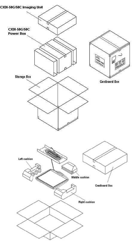
3 Packing Diagram
3.1 X-ray Digital Camera System (CXDI-50G/50C)
(1) CXDI-50G/50C assemble package
(2) CXDI-50G/50C Imaging Unit package
- 5 -

2. Installation Manual
(3) Power Box assemble package
(4) Grid (optional)
- 6 -
2. Installation Manual
4 Installation Procedures
4.1 Lists of Tool Needed for Installation
Tool needed for new installation.
No. |
Tool Name |
Unit |
Remarks |
|
1. |
General Tools |
1 set |
|
|
2. |
Note PC |
1 |
PC/AT compatible |
|
(OS: Microsoft Windows XP Professional recommend) |
||||
|
|
|
||
3. |
LAN Card |
1 |
For Note PC (as required) |
|
4. |
Mouse |
1 |
PS/2 type |
|
5. |
Keyboard |
1 |
PS/2 type |
|
6. |
HUB |
1 |
Connection between Control PC and Note PC |
|
7. |
10/100BASE-TX cable |
2 |
Straight type (Control PC to Note PC) |
|
8. |
CXDI Software version |
- |
|
|
compatibility table |
|
|||
|
|
|
||
9. |
Mirror, oil-based marker |
1 |
For adjusting the alignment with the X-ray tube. |
|
and paper etc. |
||||
|
|
|
- 7 -
2.Installation Manual
4.2System Installation Procedures
No. |
Step |
Conditions and Checkpoints |
Reference Section |
1 |
Unpacking and checking the |
-There must be no missing parts, damage, |
|
|
product’s constituent parts |
dents, etc. |
|
|
|
-There must no color changes in the shock |
|
|
|
sensor. |
|
2 |
Connect the Imaging Unit |
-Handle the instrument carefully, as it may |
|
|
and the Power Box |
be damaged if something is hit against it, |
|
|
|
dropped or receives the strong jolt. |
|
|
|
-The cable must be routed in such a way that |
|
|
|
no unreasonable loads are brought to bear |
|
|
|
upon them. |
|
3 |
Connect the Power Box and |
-The cable must be routed in such a way that |
|
|
the Control PC |
no unreasonable loads are brought to bear |
|
|
|
upon them. |
|
4 |
Connect the Power Box and |
-The manufacturer of the X-ray generators |
|
|
the X-ray generators |
must be asked to handle the connections |
|
|
|
with the generators. |
|
5 |
Check date and time |
- Date and time must be changed according |
“(1) Checking and |
|
|
to the area where the instrument is installed. |
Setting the Date and |
|
|
|
Time” in section 5.6. |
6 |
Check the software |
-The compatibility of the sensor unit and the |
“(2) Checking the |
|
program’s version |
Control PC must be checked on the |
Firmware Version” in |
|
|
compatibility list, and the software program |
section 5.6. |
|
|
must be installed or upgrade as required. |
|
7 |
Identifying the Imaging Unit |
|
“(6) Identifying the |
|
(input the sensor serial |
|
Sensor Units” in section |
|
numbers) |
|
5.6. |
8 |
Enter control PC serial |
|
“(7) Entering Control |
|
number. |
|
PC Serial Number” in |
|
|
|
section 5.6. |
(9) |
Adjusting the timing with X- |
-No required usually. |
|
|
ray generator |
|
|
10 |
Calibration |
-No error must be displayed. |
Operation Manual |
11 |
Setting the Fixed ROI Areas |
If necessary, set the ROI area. |
|
12 |
Set exposure parameter table |
-Set it in consultation with the technician. |
“(8) Table Setup |
|
|
|
Setting” in section 5.6. |
13 |
Set annotation |
-Set it in consultation with the technician. |
“(9) Performing the |
|
|
|
Annotation Setting” in |
|
|
|
section 5.6. |
14 |
Connect the network and set |
|
“(10) Network |
|
the output destination |
|
Connections” in section |
|
|
|
5.6. |
15 |
Startup settings |
|
“(5) Set Up Startup |
|
|
|
Menu” in section 5.6. |
16 |
Exposure testing |
-The data must be sent to the printer and |
Section 5.7 Image |
|
|
storage and the image quality must be |
Quality. |
|
|
checked. |
|
17 |
Check the linearity of the |
|
“(11) Linearity Check |
|
transferred image density. |
|
Image Density” in |
|
|
|
section 5.6. |
18 |
Operation unit Gamma |
|
“(12) Operation Unit |
|
correction |
|
Gamma Correction” in |
|
|
|
section 5.6. |
19 |
Body parts settings |
-The engineer in charge must be consulted |
Operation Manual |
|
|
prior to perform these settings. |
|
20 |
Check and set the system |
-The engineer in charge must be consulted |
Each section in section |
|
settings. |
prior to perform these settings. |
5.6 Settings. |
21 |
Total adjustments and delete |
-Conform according to the check sheet. |
Section 5.8 Post- |
|
the unnecessary data. |
-Delete the unnecessary data. |
installation check. |
22 |
Cleaning |
|
|
- 8 -
2. Installation Manual
23 |
Explain the operation to the |
|
Operation Manual |
|
user |
|
|
24 |
Final parameter adjustment |
-The engineer in charge must be consulted |
Operation Manual |
|
|
prior narrowing down the adjustments to the |
|
|
|
final values. |
|
25 |
Inserting the backup floppy |
-It must be confirmed at re-start that backup |
“(15) Backing up |
|
disk. |
files have been made. |
Setting Data to FD” in |
|
|
-No necessary for the system installed in |
section 5.6. |
|
|
vehicles. |
|
26 |
Back up valuable data |
|
“(14) Backing Up when |
|
|
|
Installing” in section |
|
|
|
5.6. |
- 9 -

2. Installation Manual
5 Installation
5.1 Connection to each unit
5.1.1Connection diagram
Control PC
CXDI-50G |
|
-50G/50C |
Remote switch |
POWER SUPPLY
PCBXRAY
POWER BOX
- 10 -
2. Installation Manual
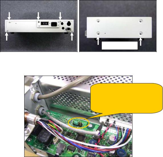
5.1.2Connecting to the Power Box
(1)Removing the cover
Remove the 5 screws from the back of the power box and the 2 screws on each side at the bottom of the power box.
Also remove screws on the far side
(2)Check the jumper pin settings on the PWB-40XRAY board in the power box. The power supplies for 7m and 3m are not compatible due to having different output voltages. This short pin is for determining the power, not for changing the voltage.
50 power unit setting
50 Power 7m : Short between JP1 6-8p 50 power 3m : Short between JP1 7-8p This setting is done when shipping
With changing the jumper pin settings, the signal sent to PLD (IC1) of the PWB-40XRAY board has either state High or Low. By using this state, the PBIF50XRAY PLD code which written in the PLD can distinguish whether the power supply is for 3m or 7m.
The Imaging unit determines the cable length based on the dip switch setting (SW1-7: OFF) on the PWB-50Di board. If cable connector P4 #1-#2 is open, cable length is 7m. If #1-#2 is connected, cable length is 3m.
- 11 -

2. Installation Manual
(3)Cable connections
1)Loosen the lock nut for each cable and connect the cables to the power box. Then fix the cables by tightening the lock nuts.
Sensor cable |
X-ray I/F cable |
Lock nut |
Remote cable |
Note: To avoid the risk of damage when the cables are removed with very large force, Check tightening torque of the bush (refer the following figure).
No gap
Gap 1.0 to 1.5mm
<Sensor cable> |
<X-RAY I/F cable, |
|
Remote cable> |
2)Attach the cable clamp to the sensor cable, and then fix it to the power box using the screw (M4 x 6 mm).
Clamp the cable’s shield portion
Cable clamp
Screw (M4×6mm)
- 12 -
")
2.Installation Manual
3)Connecting each cable connector.
Connected to
Sensor cable
X-ray I/F cable
Connected to
Remote cable
Connected to
4)After completing the connections, attach the power box cover.
5)Connect the LAN cable to the back of the power box.
LAN cable
- 13 -
Loading...