


 Loading...
Confidential
CXDI-1 System
 CXDI-31
Service Manual
Ver.06
Jun. 2009 |
Medical Products |
Copyright by |
|
Technical Service Dept |
Canon |
Manual Control No. |
: BY8-2251-0E6 |
Name of Product |
: CXDI-31 |
Distribution Control No. |
: |
Issued on |
: |
Service Manual
Introduction
This service manual belongs to a series of after-sales guides Canon Inc. publishes as part of its comprehensive product quality guarantee program, and will make a useful tool in promoting the sales of the product, let alone repairing it.
This service manual consists of nine chapters; General, Installation Manual, Imaging Unit, E/O Box, Parts Catalog, and Service Manual Report.
Please fully understand the procedure for installing the product indicated in “Installation Manual”, the features and specifications of the product indicated in “GENERAL” and principle of system and operation in “TECHNICAL INFORMATION”
Refer to “REPAIR GUIDE” in order to perform repairs properly, and “PARTS CATALOG” and “TOOLS” for ordering parts and tools.
If you are using nonstandard connections or settings, refer to the related items in the “Option Setup” chapter and then correct the connections or settings accordingly.
If the product undergoes a large modification, a new service manual of revised edition will be sent to you.
In other cases, service manual report will be sent to you to update the manual.
If needed, utilize the related information indicated in the last chapter of Appendix.
Note 1:
This service manual is published by Canon Inc. in accordance with Article 6 (Furnishing the Referring Materials) of the Service Assignment Contract concluded with your company.
The contract prohibits the exposure of the contents of this service manual in any form to the third party without a written consent of Canon Inc.
Note 2:
This service manual is property of Canon Inc. and the company may seek to have it returned, depending on circumstances. You are expected to keep it until then.
Note 3:
Your inquiries, suggestions etc. about the contents of this service manual should be addressed to: Medical Equipment Quality Administration Division,
Technical Service Department
Canon Inc.
30-2, Shimomaruko 3-chome, Ohta-ku, Tokyo 146-8501, Japan
1
1. General
This chapter is devoted to the description of the product’s features and specifications.
2. Installation Manual
This chapter indicates the procedure for installing the product.
3. Imagining Unit
This chapter describes unit composition, technical information and repair guide of Imaging Unit.
4. E/O Box
This chapter describes unit composition, technical information and repair guide of E/O Box.
5. Parts Catalog
This chapter consists of sections devoted to the product composition, disassembly diagrams, circuit diagrams and part number index.
5.1 Product Composition
The main unit and accessories of the product are described.
A.The accessories whose order numbers are listed in the section are available from the Sales Section as merchandise.
5.2Disassembly Diagram
The parts specified as repair part are described, classified into groups from the function standpoint.
A.Unit Part and Its Constituent Parts
Example
2
B. Part No. Column
A part number marking is as follows :
General Parts
Size number
Part number
Revision number
Characteristic number
Sorting number
Standard Parts (Screws, washers, resistors, capacitors, etc.) of Standard Specification
0 
 0
0 
 0
0
Supplementary number
Part number
Revision number
Sorting number
Size number: |
This number is used to classify adjustment parts by size. |
|
The marking is 000 for parts which need not be classified by size. |
Revision Number: |
This number is used to distinguish new parts from old ones. |
|
The number advances when they cease to be interchangeable due to |
|
modification. |
Supplementary number: |
This is simply used to ensure the general and standard part number of |
|
the same length. The marking is always 000. |
Standard number: |
This is used to indicate screw diameters, resistance values, etc. |
3

The size and supplementary number 000 marking is omitted.
The size number is given into ( ) below the part number for only adjustment parts.
Example … BA03415-000 … 020 : t= 0.2mm 050 : t= 0.5mm 100 : t =1.0mm
The parts whose part numbers are listed together and enclosed in ( ) are adjustment parts,
Example … |
XD1-1108-221 |
|
XD1-1108-222 |
|
XD1-1108-225 |
C. Q’ty Column
The number of units of parts used in the mechanism are indicated.
The marking is N for those adjustment parts which are not used in uniform quantities.
The marking is 1 for those parts whose length is not specified in the part number. Their length by standard specified is given in ( ) below the part number in the PARTS NO. column.
Example … BH-2184-000 … 1 …
( l = 20mm)
5.3 Circuit Diagram
Electrical repair parts which are difficult to be showed in disassembly diagrams are illustrated.
5.4 Part Number Index
Except for the standard parts all the repair parts showed in disassembly and circuit diagrams are listed in the order of the part number.
The page where the part is listed is found by referring its part number.
REVISION NO. – REPORT NO. Column
Informed of an advanced revision number by the Service Manual Report, the customer enters the new revision number and the report number in this column.
A.REVISION NO.-REPORT NO Column
Informed of an advanced revision number by the Service Manual Report, the customer enters the new revision and the report number in this column.
4
6. Service Manual Report
This report informs you of changes in the product design, etc., complete with information on the reason of the changes, their contents and repair instructions.
When you receive the Service Manual Report, you are advised to enter the necessary information in the service manual and keep the report in the report file according to the filing number.
5
CAUTION
Follow the safety instructions indicated below. Ignoring them may result in injury or accident.
1. Disassembly, Assembly, Adjustment and Maintenance
Disassembly, assembly, adjustment and maintenance must be done only by a service person who has attended a service training designated by Canon.
2. Removal of Covers
Be sure to turn OFF the power of the instrument before removing the covers for maintenance and repair. Also, do not touch the instrument with wet hands. Otherwise, you may get an electric shock that may result in death or serious injury.
3. Fuse
When the fuse is going to be replaced, be sure to turn OFF the power of the instrument and solve the problem which caused the fuse to blow. Be sure to replace the fuse with the specified type only. Otherwise, fire or electric shock may result.
4. Ground Wire
Be sure to ground the instrument to an indoor grounded connector. Otherwise, fire or electric shock may result due to leakage.
5. Modification
Never modify the product as it may result in fire or electric shock.
6. Waste control
The service provider is responsible for the disposal of used service parts, packing material, etc. resulting from the setup, repair or maintenance of the medical device However, the customer is responsible for the disposal of the medical device. Disposal activities must follow the regulations (=specially controlled industrial waste) of the country where the device is used.
VORSICHT
Befolgen Sie die unten angegebenen Sicherheitsanweisungen.
Mißachtung kann zu erletzungenoder Unfällen führen.
1.Zerlegung, Zusammenbau, Einstellung und Wartung
Zerlegung, Zusammenbau, Einstellung und Wartung dürfen nur von einem Wartungstechniker durchgeführt werden, der an einem von Canon vorgeschriebenen Wartungslehrgang teilgenommen hat.
2.Entfernen von Abdeckungen
Schalten Sie unbedingt die Stromversorgung des Instruments aus, bevor Sie die Abdeckungen zwecks Wartung und Reparatur entfernen.
Vermeiden Sie auch eine Berührung des Instruments mit nassen Händen.
Anderenfalls können Sie einen elektrischen Schlag erleiden, der zum Tod oder schwerer Verletzung führen kann.
3.Sicherung
Wenn die Sicherung ausgewechselt werden muß, schalten Sie unbedingt die Stromversorgung des Instruments aus, und beheben Sie die Ursache für das Durchbrennen der Sicherung.
Ersetzen Sie die Sicherung nur durch den vorgeschriebenen Typ. Anderenfalls kann es zu einem Brand oder elektrischen Schlag kommen.
4.Erdleiter
Erden Sie das Instrument unbedingt an einer Schukosteckdose.
Anderenfalls kann es zu einem Brand oder elektrischen Schlag durch Leckstrom kommen.
5.Umbau
Jeder Umbau des Produktes ist strengstens untersagt, da dies zu einem Brand oder elektrischen Schlag führen kann.
Labels and Markings
Labels and Markings
Safety Information(CXDI-31)
For U. S. A.
Do not make any changes or modifications to the equipment unless otherwise specified in the manual.
If such changes or modifications should be made, you could be required to stop operation of the equipment.
NOTE:
This equipment has been tested and found to comply with the limits for a Class A digital device, pursuant to Part 15 of the FCC rules.
These limits are designed to provide reasonable protection against harmful interference when the equipment is operated in a commercial environment.
This equipment generates, uses, and can radiate radio frequency energy and, if not installed and used in accordance with the instruction manual, may cause harmful interference to radio communications.
Operation of this equipment in a residential area is likely to cause harmful interference in which case the user will be required to correct the interference at his own expense.
Use of shielded cable is required to comply with class A limits in Subpart B of Part 15 of FCC rules.
i

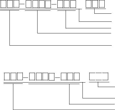
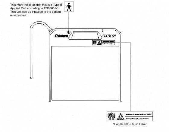
Labels and Markings
Labels and Markings on the Instrument
The CXDI-31 has a few labels and markings on it.
Contents of them and positions where they are attached are indicated below.
Front
ii
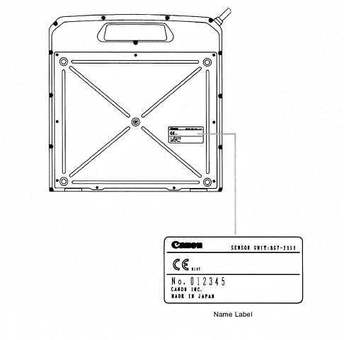
Labels and Markings
Rear
iii

Labels and Markings
For EU Countries
The following mark shows compliance of the instrument with Directive 93/42/EEC.
This instrument has been classified into EN55011 Group 1/Class A.
This instrument is a CLASS I EQUIPMENT according to EN 60601-1.
This instrument has been classified under EN60825-1:1994 and conforms to the following classes:
CLASS 1 LASER PRODUCT LASER KLASSE 1
APPAREIL A RAYONNEMENT LASER DE CLASSE 1 APPARECCHIO LASER DI CLASSE 1
PRODUCTO LASER DE CLASE 1 APARELHO A LASER DE CLASSE 1
iv
Labels and Markings
Labels and Markings on the Instrument
The CXDI-31 has a few labels and markings on it.
Contents of them and positions where they are attached are indicated below.
Front
v
Labels and Markings
Rear
vi
Labels and Markings
Safety Information(E/O Box)
For EU Countries
The E/O box has been classified under EN60825-1:1994 and conforms to the following classes:
CLASS 1 LASER PRODUCT LASER KLASSE 1
APPAREIL A RAYONNEMENT LASER DE CLASSE 1 APPARECCHIO LASER DI CLASSE 1
PRODUCTO LASER DE CLASE 1 APARELHO A LASER DE CLASSE 1
The E/O box has been classified into EN55011 Group 1/Class A.
For U. S. A.
Do not make any changes or modifications to the equipment unless otherwise specified in the manual.
If such changes or modifications should be made, you could be required to stop operation of the equipment.
NOTE:
This equipment has been tested and found to comply with the limits for a Class A digital device, pursuant to Part 15 of the FCC rules.
These limits are designed to provide reasonable protection against harmful interference when the equipment is operated in a commercial environment.
This equipment generates, uses, and can radiate radio frequency energy and, if not installed and used in accordance with the instruction manual, may cause harmful interference to radio communications.
Operation of this equipment in a residential area is likely to cause harmful interference in which case the user will be required to correct the interference at his own expense.
Use of shielded cable is required to comply with class A limits in Subpart B of Part 15 of FCC rules.
vii
Labels and Markings
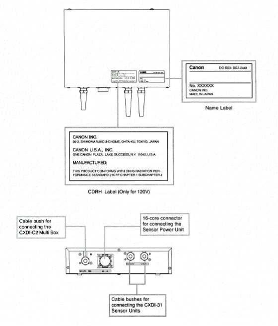
Labels and Markings on the Instrument
The E/O box has a few labels and markings on it.
Contents of them and positions where they are attached are indicated below.
viii

CXDI-31
1.General
Ver.01
August, 2001 |
Medical Products |
Copyright by |
|
Technical Service Dept |
Canon |
1 General
|
|
CONTENTS |
1.CXDI-1 System Block Diagram |
........................................................................ 1 |
|
2.CXDI Image Processing .................................................................................. |
2 |
|
2.1 |
Processing Flow........................................................................................ |
2 |
2.2 |
Image Types ............................................................................................. |
3 |

1.GENERAL
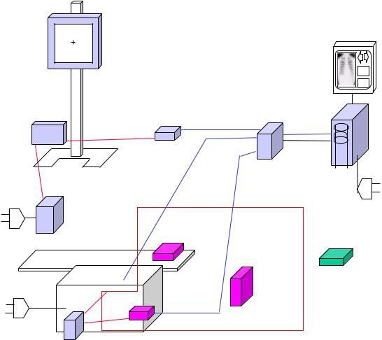
1.CXDI-1 SYSTEM BLOCK DIAGRAM (CXDI-31)
* 1. |
|
: Connector |
* 2. |
|
: Ferrite Core |
|
||
|
||
* 3. |
|
: Cord Bush |
* 4. |
|
: Option |
|
||
|
|
|
|
|
|
|
|
|
|
|
|
|
|
|
|
|
|
|
|
|
|
|
|
|
|
|
|
|
|
|
|
|
|
|
|
|
|
|
|
|
Table |
|
|
|
|
|
|
|
|
|
|
||||
|
|
|
|
|
|
|
|
|
|
|
|
|
|
|
|
|
|
|
|
|
Sensor Power |
|
|
|
|
|
|
|
|
|
|
|
|
|
|
|
|
|
|
|
|
|
|
|
|
|
|
|
|
|
||||
|
|
|
|
|
|
|
|
|
|
|
|
|
|
|
|
|
|
|
|
|
|
|
|
|
|
|
|
|
|
Imaging Unit |
|
|
|
|
|
|
|
|
|
|
||||||||||||||
|
|
|
|
|
|
|
|
|
|
|
|
|
|
|
|
|
|
|
|
|
|
Supply Unit |
|
|
|
|
|
|
|
|
|
|
|
|
|
|
|
|
|
|
|
|||||||||||||
AC100V/120V/220/240V |
|
|
|
|
CA4 |
|
|
|
|
|
|
SPW |
|
|
|
|
|
|
|
|
|
|
(CXDI-22) |
|
|
|
|
|
CA17 |
|||||||||||||||||||||||||
|
|
|
|
|
|
|
|
|
|
|
|
|
AC Power IN |
|
|
|
|
|
|
CA2 |
|
|
|
|
|
|
|
|
|
|
Ready |
|
|
|
|
|
||||||||||||||||||
|
(AC85-264V) |
|
|
|
|
|
|
CA3 |
|
|
|
|
|
|
|
|
OUT PUT 1 |
|
|
|
|
|
DC Power |
|
Lamp |
|
|
|
|
|
|
|
|
|
|
|||||||||||||||||||
|
|
|
|
|
|
|
|
|
|
|
|
|
|
|
|
|
|
|
|
|
|
|
|
|
|
|
|
|
|
|||||||||||||||||||||||||
|
|
|
|
|
|
|
|
|
|
|
|
|
|
FG |
|
|
|
(DC Power) |
|
|
|
|
|
|
|
|
|
|
|
|
CA3 |
|||||||||||||||||||||||
|
|
|
|
|
|
|
|
|
|
|
|
|
|
|
|
|
|
|
|
|
|
|
|
|
|
|
|
|
|
|
||||||||||||||||||||||||
|
|
|
|
|
|
|
|
|
|
|
|
|
|
|
|
|
|
OUT PUT 2 |
OUT PUT 3 |
|
|
|
|
|
|
|
|
|
|
METAL- |
|
|
FG |
|
|
|||||||||||||||||||
|
|
|
|
|
|
|
|
|
|
|
|
|
|
|
|
|
|
|
|
|
|
|
|
|
|
|
|
|
|
|
|
|
|
|
|
|
|
|
|
|||||||||||||||
|
|
|
|
|
|
|
|
|
|
|
|
|
|
|
|
|
|
|
|
|
|
|
|
|
|
|
|
|
|
|
|
|
|
|
|
|
|
|
|
|||||||||||||||
|
|
|
|
|
|
|
|
|
|
|
|
|
|
|
|
|
|
(DC Power) |
(DC Power) |
|
|
|
|
|
|
|
|
|
|
OPTICAL |
|
|
|
|
|
|
|
|
|
|
|
|
|
|||||||||||
|
|
|
|
|
|
|
|
|
|
|
|
|
|
|
|
|
|
|
|
|
|
|
|
|
|
|
|
|
|
|
|
|
|
|
|
|
|
|
|
|
|
|
|
|||||||||||
|
|
|
|
|
|
|
|
|
|
|
|
|
|
|
|
|
|
|
|
|
|
|
|
|
|
|
|
|
|
|
|
|
|
|
|
|
|
|
|
|
|
|
|
|
|
|
|
|
|
|
|
|
|
|
|
|
|
|
|
|
|
|
|
|
|
|
|
|
|
|
|
|
|
|
|
|
|
|
|
|
|
|
|
|
|
|
|
|
|
|
|
|
|
|
|
|
|
|
|
|
|
|
|
|
|
|
|
|
|
|
|
|
|
|
|
|
|
|
|
|
|
|
|
|
|
|
|
|
|
|
|
|
|
|
|
|
|
|
|
|
|
|
|
|
|
|
|
|
|
|
|
|
|
|
|
|
|
|
|
|
|
|
|
|
|
|
|
|
|
|
|
|
|
|
|
|
|
|
|
|
|
|
|
|
|
|
|
|
|
|
|
|
|
|
|
|
|
|
|
|
|
|
|
|
|
|
|
|
|
|
|
|
|
|
|
|
|
|
|
|
|
|
|
|
|
|
|
|
|
|
|
|
|
|
|
|
|
|
|
|
|
|
|
|
|
|
|
|
|
|
|
|
|
|
CA1 |
|
|
|
|
|
|
|
|
|
|
|
|
|
|
|
|
|||
|
|
|
|
|
|
|
|
|
|
|
|
|
|
|
|
|
|
|
|
|
|
|
|
|
|
|
|
|
|
|
|
|
|
|
|
|
|
|
|
|
|
|
|
|
|
|
|
|
|
|
||||
|
|
|
|
|
|
|
|
|
|
|
|
|
|
|
|
|
|
|
|
|
|
|
|
|
|
|
|
|
|
|
|
|
|
|
|
|
|
|
|
|
|
|
|
|
|
|
|
|
|
|
||||
|
|
|
|
|
|
|
|
|
|
|
|
|
|
|
|
|
|
|
|
|
|
|
|
|
|
|
|
|
|
|
|
|
|
|
|
|
|
|
|
|
|
|
|
|
|
|
|
|
|
|
|
|
|
|
|
|
|
|
|
|
|
|
|
|
|
|
|
|
|
|
|
|
|
|
|
|
|
|
|
|
|
|
|
|
|
|
|
|
|
|
|
|
|
|
|
|
|
|
|
|
|
|
|
|
|
|
|
|
|
|
|
|
|
|
|
|
|
|
|
|
|
|
|
|
|
|
|
|
|
|
|
|
|
|
|
|
|
|
|
|
|
|
|
|
|
|
|
|
|
|
|
|
|
|
|
|
|
|
|
|
|
|
|
|
|
|
|
|
|
|
|
|
|
|
|
|
|
|
|
|
|
|
DC Power |
|
|
|
|
|
|
|
|
|
|
|
|
|
METAL- |
|
|
|
|
MULTI- |
|
||||||||||||||||
|
|
|
|
|
|
|
|
|
|
|
|
|
|
|
|
|
|
|
|
|
|
|
|
|
|
|
|
|
|
|
|
|
|
|
|
OPTICAL 1 |
|
|
||||||||||||||||
|
|
|
|
|
|
|
|
|
|
|
|
|
|
|
|
|
|
|
|
|
|
|
|
|
|
|
|
|
|
|
|
|
|
|
|
(CXDI-22) |
|
|
|
|
METAL |
|
||||||||||||
|
|
|
|
|
|
|
|
I/F Board |
|
|
|
|
|
|
|
|
|
|
|
|
|
|
|
|
Multi Box |
MULTI- |
|
|||||||||||||||||||||||||||
|
|
|
|
|
|
|
SENSOR 2 |
|
|
|
|
|
|
|
|
|
|
|
|
|
|
|
|
|
|
|
|
|
|
|
|
|
|
|
|
|
||||||||||||||||||
|
|
|
|
|
|
|
|
|
|
|
|
|
|
|
|
|
|
|
|
|
|
|
|
|
|
|
|
|
|
|
|
|
|
|
OPTICAL |
|
||||||||||||||||||
|
|
|
|
|
|
|
(CXDI-31) |
|
|
|
|
|
METAL- |
|
|
|
|
|
|
|
|
|
|
|
METAL- |
|
|
|
|
|||||||||||||||||||||||||
|
|
|
|
|
|
|
|
|
|
|
|
|
|
|
|
|
|
|
|
|
|
|
|
|
|
|
|
|
|
|
|
|
|
|
|
|||||||||||||||||||
|
|
|
|
|
|
|
|
|
|
|
|
|
|
|
|
|
|
|
|
|
|
|
|
|
|
|
|
|
|
|
|
|
|
|
|
|
|
|
|
|
|
|
|
|
|
|||||||||
|
|
|
|
|
|
|
|
|
|
|
|
|
|
|
|
|
|
|
|
|
|
OPTICAL |
|
|
|
|
|
|
|
|
|
|
|
OPTICAL 2 |
|
|
|
|
|
|
|
|
|
|
|
|
|
|||||||
|
|
|
|
|
|
|
SENSOR 1 |
|
|
|
|
|
|
|
|
|
|
|
|
|
|
|
|
|
|
(CXDI-31,E/O Box) |
|
|
|
|
|
|
|
|
|
|
||||||||||||||||||
|
|
|
|
|
|
|
|
|
|
|
|
|
|
|
|
|
|
|
|
|
|
|
|
|
|
|
|
|
|
|
|
|
|
|||||||||||||||||||||
|
|
|
|
|
|
|
(CXDI-31) |
|
|
|
|
|
|
|
|
|
|
|
|
|
|
|
|
|
|
METAL- |
|
|
|
|
|
|
|
|
|
|
|
|
|
|||||||||||||||
|
|
|
|
|
|
|
|
|
|
|
|
|
|
|
|
|
|
|
|
|
|
|
|
|
|
|
|
|
|
|
|
|
|
|
|
|
||||||||||||||||||
|
|
|
|
|
|
|
|
|
|
|
|
|
|
|
|
|
|
|
|
|
|
|
|
|
|
|
|
|
|
|
|
|
|
|
OPTICAL 3 |
|
|
|
|
|
|
|
|
|
|
|
|
|
||||||
|
|
|
|
|
|
|
|
|
|
|
|
|
|
|
|
|
|
|
|
|
|
|
|
|
|
|
|
|
|
|
|
|
|
|
(E/O Box) |
|
|
|
|
|
|
|
|
|
|
|
|
|
||||||
|
|
|
|
|
|
|
|
|
|
|
|
|
|
|
|
|
|
|
|
31E/O Box |
|
|
|
|
|
|
|
|
|
|
|
|
|
|
|
|
|
|
|
|
|
|
|
|||||||||||
|
|
|
|
|
|
|
|
|
|
|
|
|
|
|
|
|
|
|
|
|
|
|
|
|
|
|
|
|
|
|
|
|
|
|
|
|
|
|
|
|
|
|
|
|
|
|
|
|
|
|||||
|
|
|
|
|
|
|
|
|
|
|
|
|
|
|
|
|
|
|
|
|
|
|
|
|
|
|
|
|
|
|
|
|
|
|
X-Ray |
Tube |
|
Tube |
|
|||||||||||||||
|
|
|
|
|
|
|
|
|
|
|
|
|
|
|
|
|
|
|
|
|
|
|
|
|
|
|
|
|
|
|
|
|
|
|||||||||||||||||||||
|
|
|
|
|
|
|
|
|
|
|
|
|
|
|
|
|
|
|
|
|
|
|
|
|
|
|
|
|
|
|
|
|
|
|
I/F |
Sync 1 |
|
Sync 2 |
|
|||||||||||||||
|
|
|
|
|
|
|
|
|
|
|
|
|
|
|
|
|
|
|
|
|
|
|
|
|
|
|
|
|
|
|
|
|
|
|
|
|
||||||||||||||||||
Imaging Unit |
|
|
|
|
|
|
|
|
|
|
|
|
|
|
|
|
|
|
|
|
|
|
|
|
|
|
|
|
|
|
|
|
|
|
|
|
|
|
|
|
|
|
|
|
|
|
|
|
|
|
|
|||
|
|
|
|
|
|
|
|
|
|
|
|
|
|
|
|
|
|
|
|
|
|
|
|
|
|
|
|
|
|
|
|
|
|
|
|
|
|
|
|
|
|
|
|
|
|
|
|
|
|
|
||||
|
|
|
|
|
|
|
|
|
|
|
|
|
|
|
|
|
|
|
|
|
|
|
|
|
|
|
|
|
|
|
CA5 |
|
|
|
|
|
|
|
|
|
|
|
|
|
|
|
|
|
|
|||||
(CXDI-31) |
|
|
|
|
|
|
|
|
|
|
|
|
|
|
|
|
|
|
|
|
|
|
|
|
|
|
|
|
|
|
|
|
|
|
|
|
|
|
|
|
|
|
|
|
|
|
|
|
|
|||||
|
|
|
|
|
|
|
|
|
|
|
|
|
|
|
|
|
|
|
|
|
|
|
|
|
|
|
|
|
|
|
|
|
|
|
|
|
|
|
|
|
|
|
|
|
|
|
|
|
|
|
||||
|
|
|
|
|
|
|
|
|
|
|
|
|
|
|
|
|
|
|
|
|
|
|
|
|
|
|
|
|
|
|
|
|
|
|
|
|
|
|
|
|
|
|
|
|
|
|
|
|
|
|
|
|
|
|
|
|
|
|
|
|
|
|
|
|
|
|
|
|
|
|
|
|
|
|
|
|
|
|
|
|
|
|
|
|
|
|
|
|
|
|
|
|
|
|
|
|
|
|
|
|
|
|
|
|
|
|
|
|
|
X-Ray Generator
AC120V
AC230V
Ready
Lamp
|
|
|
|
|
|
|
|
|
|
|
|
|
|
|
|
|
|
|
|
|
|
DC12V |
|
|
|
|
|
|
|
|
|
OPERATION |
|
|
|
|
CA9 |
|
|
|
Operation |
||||||||||
|
|
|
|
|
|
|
|
|
|
|
|
|
|||||||||||||
|
|
|
Control PC |
|
|
|
|
|
|
|
|
|
|
|
|
|
RS232C |
Unit |
|||||||
|
|
|
|
|
|
|
|
|
|
CA8 |
|
||||||||||||||
|
|
|
|
|
VGA |
|
|
|
|
|
VGA |
|
|
||||||||||||
|
|
|
(CXDI-C2) |
|
|
|
|
|
|
|
|
|
|
|
|
|
|
|
|
|
|||||
|
|
|
|
|
|
|
|
|
|
|
|
|
|
|
|
|
|
||||||||
|
|
|
|
|
|
|
|
|
|
|
|
|
|
|
|
|
|
|
|
|
|
|
|
|
|
|
|
|
|
|
|
|
|
|
|
|
|
|
|
|
|
|
|
|
|
||||||
|
CA11 |
|
MULTI- |
SERIAL1 |
|
|
|
|
|
|
|
|
|
|
|
|
|
RS232C |
ID Unit |
||||||
|
|
|
|
|
|
|
|
|
|
|
|
|
|
|
|||||||||||
|
|
|
|
|
|
|
|
|
|
|
|
||||||||||||||
|
CA12 |
|
METAL |
|
|
|
|
|
|
|
|
|
|
|
|
|
|
|
|
|
|
(Option) |
|||
|
|
|
|
|
|
|
|
|
|
|
|
|
|
|
|
|
|
|
|
|
|
|
|
|
|
|
|
|
|
|
|
|
|
|
|
|
|
|
|
|
|
|
|
|
|
||||||
|
|
MULTI- |
|
MOUSE |
|
|
|
|
|
|
|
|
|
|
|
|
|
|
Mouse |
|
|||||
|
|
|
|
|
|
|
|
|
|
|
|
|
|
|
|
|
|
||||||||
|
|
|
OPTICAL |
KEY BOARD |
|
|
|
|
|
|
|
|
|
|
|
|
|
|
|
|
|
||||
|
|
|
|
|
|
|
|
|
|
|
|
|
|
|
|
|
|
|
|
||||||
|
|
|
|
|
|
|
|
|
|
|
|
|
|
|
|
|
|
|
|
|
|
|
|||
|
|
|
|
|
|
|
|
|
|
|
|
|
|
|
|
|
|
|
|
Key Board |
|
||||
|
|
|
|
|
|
|
|
|
|
|
|
|
|
|
|
|
|
|
|
|
|||||
|
|
|
|
|
|
|
|
|
|
|
|
|
|
|
|
|
|
|
|
|
|
|
|
||
|
|
|
|
|
|
|
|
|
|
|
|
|
|
|
|
|
|
|
|
|
|
|
|
|
|
|
|
|
|
|
|
|
|
|
|
|
|
|
|
|
|
|
|
|
|
|
|
|
|
|
|
|
|
|
|
|
|
|
|
LAN |
|
|
|
|
CA10 |
|
|
|
|
|
|||||||
|
|
|
|
|
|
|
|
|
|
|
|
|
|
||||||||||||
|
|
|
|
|
|
|
SCSI |
|
|
|
|
|
|
Printer |
|||||||||||
|
|
|
|
|
|
|
|
|
|
|
|
|
|
|
|
|
|
|
|
|
|||||
|
|
|
|
|
|
|
|
|
|
|
|
|
|
|
|
|
|
|
|
|
|||||
|
|
|
|
|
|
|
|
|
|
|
|
|
|
|
|
|
|
|
|
||||||
|
|
|
|
|
SERIAL2(COM3) |
|
|
|
|
|
|
|
|
|
|
|
|
|
|
||||||
|
|
|
|
|
|
|
|
|
|
|
|
|
|
|
|
|
|
|
|||||||
|
|
|
|
|
|
|
|
|
|
|
|
|
|
|
|
|
|
|
|
|
|
|
|||
|
|
|
|
|
SERIAL2(COM4) |
|
|
|
|
|
|
|
|
|
|
|
|
|
Image diagnosis |
||||||
|
|
|
|
|
|
|
|
|
|
|
|
|
|
|
|
|
|
||||||||
|
|
|
FG |
AC Power IN |
|
|
|
|
|
|
|
|
|
|
|
|
|
||||||||
|
|
|
|
|
|
|
|
|
|
|
|
|
|
|
|
||||||||||
|
|
|
|
|
|
|
|
|
|
|
|
|
|
|
|
|
|
W/S |
|||||||
|
|
|
|
|
|
|
|
|
|
|
|
|
|
|
|
|
|
|
|
|
|
|
|
||
|
|
|
|
|
|
|
|
|
|
|
|
|
|
|
|
|
|
|
|
|
|
|
|
|
|
CA7
CA6
Image file device
AC120V±10% 60Hz 2A |
|
AC230V±10% 50/60Hz 1.5A |
Network |
|
|
|
Ethernet |
|
(100/10bese-T) |
1

1. GENERAL
2. CXDI Image Processing
2.1Processing flow
|
|
|
Born image |
|
Offset correction |
|
|
|
|
|
|
|
|
|
|
|
|
|
|
|
|
|
|
Correction |
Gain correction |
|
|
|
|
|
processing |
|
|
|
|
|
|
|
|
|
|
MTF improvement |
|
|
Raw image |
|
Defect correction |
dtstore |
|
|
|
|
|
||
(Frequency |
|
|
|
|
|
|
|
Pre- |
|
|
|||
improvement |
|
|
|
|||
|
processing |
|
|
|||
processing) |
|
Seamless |
|
|||
|
|
|
|
|
||
|
|
|
Original image |
|
correction |
|
|
|
|
|
|
|
|
|
|
|
|
QA processing |
|
|
|
|
|
|
|
||
|
|
|
|
|
Characteristic |
|
|
|
|
QA image |
|
|
|
|
|
|
|
extraction |
|
|
|
|
|
|
|
|
|
|
|
|
DICOM output |
Sharpening |
|
|
|
|
|
|
|
|
|
|
|
|
|
|
|
|
|
|
|
Diag. image |
|
DEP |
|
|
|
|
|
|
|
|
|
|
|
|
|
Gradation |
|
|
|
|
|
|
processing |
|
|
|
|
Processed image |
|
|
|
|
|
|
|
|
|
|
|
|
|
|
|
|
|
2
1. GENERAL
2.2Image types
(1)Born image
The image obtained with LANMIT before any correction is made.
Outside distribution of these images is prohibited, including dtstore images.
(2)Raw image
Born image after offset processing, gain correction, and splice processing. This is the image with LANMIT specific characteristics corrected.
(3)Original image
Raw image after preprocessing.
(4)QA image
Original image after gradation processing, sharpening, and other processing. The CXDI performs image processing up to this point.
(5)Diagnosis image
QA image after further image processing necessary for diagnosis. Image processed by the user for diagnostic purposes.
(6)Processing image
Diagnosis image after post-processing.
Image modified by the user or the default processed image.
3

CXDI-31
2. Installation Manual
Ver.03
|
Aug, 2005 |
Medical Products |
Copyright by |
|
|||
|
|||
|
|||
|
|||
|
Technical Service Dept |
Canon |
|
|
|||
|
|
|
|
|
|
|
|
2 Installation Manual
|
|
|
CONTENTS |
|
System Overview ............................................................................................................ |
1 |
|||
1. |
Caution during operating ....................................................................................... |
2 |
||
2. |
Installation................................................................................................................ |
3 |
||
2.1. List of Tools Needed for Installation ............................................................................. |
3 |
|||
2.2. CXDI-31 system installation procedure......................................................................... |
4 |
|||
3. |
Unpacking ................................................................................................................ |
6 |
||
3.1. |
Product configuration..................................................................................................... |
6 |
||
|
3.1.1. |
|
Digital X-ray camera CXDI-31.............................................................................. |
6 |
|
3.1.2. |
|
Grid (Optional) ....................................................................................................... |
6 |
|
3.1.3. |
|
Product configuration guide ................................................................................... |
7 |
3.2. |
Packing diagram............................................................................................................. |
9 |
||
|
3.2.1. |
|
Digital X-ray camera ............................................................................................. |
9 |
|
3.2.2. |
|
Imaging unit ........................................................................................................... |
9 |
|
3.2.3. |
|
E/O box ................................................................................................................ |
10 |
|
3.2.4. |
|
Accessories (storage box)..................................................................................... |
10 |
4. |
Installation.............................................................................................................. |
11 |
||
4.1. |
Connecting the units .................................................................................................... |
11 |
||
|
4.1.1. |
|
Connecting block diagram.................................................................................... |
11 |
|
4.1.2. |
|
Imaging unit and E/O box .................................................................................... |
12 |
|
4.1.3. |
|
Imaging Unit and Multi box................................................................................. |
14 |
|
4.1.4. |
|
Control PC Rear Panel Connectors ...................................................................... |
15 |
|
4.1.5. |
|
Attaching photocoupler cable to the control PC unit ........................................... |
16 |
4.2. Methods for Securing the E/O Box.............................................................................. |
18 |
|||
|
4.2.1. |
|
Simple set-up for a general-purpose table for over including Pausch’s table ...... |
18 |
|
4.2.2. |
|
Set up for the storage box..................................................................................... |
19 |
4.3. |
Settings........................................................................................................................ |
21 |
||
|
4.3.1. |
|
Checking and Setting the Date and Time............................................................ |
21 |
|
4.3.2. |
|
LANMIT Image Correction ................................................................................ |
22 |
|
4.3.3. |
|
Checking the Firmware Version.......................................................................... |
25 |
|
4.3.4. |
|
Installing A/D Board Exposure Code.................................................................. |
29 |
|
4.3.5. |
|
Checking the Sensor Serial No............................................................................ |
31 |
|
4.3.6. |
|
Set Up Startup Menu ........................................................................................... |
35 |
|
4.3.7. |
|
Identifying the sensor units and setting the number of units to be connected..... |
38 |
|
4.3.8. |
|
Entering Control PC Serial Number.................................................................... |
42 |
|
4.3.9. |
|
TABLE SETUP Settings..................................................................................... |
44 |
|
4.3.10. |
Performing the annotation settings...................................................................... |
45 |
|
|
4.3.11. |
Network connections........................................................................................... |
46 |
|
|
4.3.12. |
Linearity Check of Transfer Image Density........................................................ |
78 |
|
|
4.3.13. |
Operation Unit Gamma Correction ..................................................................... |
87 |
|
|
4.3.14. |
Changing the Total Image Count ........................................................................ |
91 |
|
|
4.3.15. |
Backing Up When Installing ............................................................................... |
93 |
|
|
4.3.16. |
Backing up Important Setting Data ..................................................................... |
97 |
|
|
4.3.17. |
Tool Modes ......................................................................................................... |
99 |
|
2 Installation Manual
5. |
X-ray Controller Interface.................................................................................. |
104 |
||
5.1. |
Interface Signal Description ....................................................................................... |
104 |
||
5.2. Signal Names and Functions in X-ray Generator Connections .................................. |
105 |
|||
5.3. Ratings and Performance for Relays and Photocouplers............................................ |
106 |
|||
5.4. Adjusting the Timing with the X-ray Generator......................................................... |
110 |
|||
6. |
Image Quality Check ........................................................................................... |
117 |
||
7. |
Post-installation checks ....................................................................................... |
122 |
||
7.1. |
Check sheet................................................................................................................. |
122 |
||
8. |
External Dimensional Diagram .......................................................................... |
124 |
||
8.1. |
CXDI-31 ..................................................................................................................... |
124 |
||
|
8.1.1. |
Imaging unit ........................................................................................................ |
124 |
|
|
8.1.2. |
E/O Box............................................................................................................... |
124 |
|
|
8.1.3. |
Storage Box ......................................................................................................... |
125 |
|
8.2. |
Option ......................................................................................................................... |
126 |
||
|
8.2.1. |
Grid...................................................................................................................... |
126 |
|
9. |
Specifications & Standards ................................................................................. |
127 |
||
9.1. |
Specifications.............................................................................................................. |
127 |
||
|
9.1.1. |
9.1.1 Imaging unit................................................................................................ |
127 |
|
|
9.1.2. |
E/O box................................................................................................................ |
127 |
|
|
9.1.3. |
Grid (optional)..................................................................................................... |
128 |
|
|
9.1.4. |
Shooting environment ......................................................................................... |
128 |
|
|
9.1.5. |
Environment-related operating parameters ......................................................... |
128 |
|
9.2. |
Standards .................................................................................................................... |
128 |
||
|
9.2.1. |
Limit of Load....................................................................................................... |
128 |
|
2. Installation Manual
System Overview
CXDI-11
OPU
11 Sensor |
Power Supply |
11 E/O Box |
Control PC |
||||
|
|
|
|
|
|
|
|
|
|
|
|
|
|
|
|
|
|
|
|
|
|
|
|
|
|
|
|
|
|
|
|
Multi Box
Upright Stand
Power Transformer
CXDI-31
CXDI-22
Imaging Unit
Density: 60/cm 4:1, 8:1, 10:1 110cm
Storage Box
31 E/O Box
22 Sensor Power Supply
[Fig.1]
- 1 -
2.Installation Manual
1.Caution during operating
Please pay attention to the following points when installing the machine.
(1)If the equipment is hoisted, lowered or transported, it must be supported at both sides by a minimum of two people so there is no danger of it falling.
(2)If a forklift, etc. is used to transport the equipment, make sure there is nothing that could impede the forklift on its route to the final destination.
(3)When installing the equipment, be sure the site meets the following criteria:
1)There must be no dripping water in the area.
2)The environment must be free of harmful elements, such as humid or acidic air, air with a saline or sulfur content, where there is poor ventilation, or where air pressure or temperature is abnormal.
3)The equipment must not be placed at an angle or subjected to vibration or shock (this includes during transportation).
4)The equipment must not be kept where chemical products are stored or where gasses are generated
5)The site’s power supply must be of the correct voltage and frequency for the equipment.
6)The site must be connected to a fully earthed cable with sufficient ground resistance to meet standard values.
(4)After installation, be sure to dispose of waste product packaging with care and with full respect for the environment.
(5)As the imaging unit is easily portable, take special care that it is not knocked, dropped or subjected to strong shocks.
(6)Use clamps to secure any excess cable for the imaging unit.
- 2 -
2. Installation Manual
2. Installation
2.1. List of Tools Needed for Installation
Tools needed for new installation
No. |
Tools name |
Qty |
|
Remarks |
1 |
General tools |
1 set |
|
|
|
|
|
|
PC/AT compatible |
2 |
Laptop PC |
1 |
|
[OS:Windows 9X/ |
|
|
|
|
WindowsNT workstation 4.0 or later] |
3 |
LAN card |
1 |
|
For laptop PC [If necessary] |
4 |
Flash1 |
1 |
|
Flash1 unit, accessory cable, |
|
accessory software |
|||
|
|
|
|
|
|
|
|
|
Straight type |
5 |
RS-232C cable |
1 |
|
[For connection between Laptop PC to |
|
|
|
|
Flash1] |
6 |
Capture board I/F cable |
1 |
|
BY9-6484-000 |
7 |
Mouse |
1 |
|
PS/2 type |
8 |
Keyboard |
1 |
|
PS/2 type |
9 |
Hub |
1 |
|
For connection between control PC to |
|
Laptop PC |
|||
|
|
|
|
|
|
|
|
|
Straight type |
10 |
10BASE-T cable |
2 |
|
[For connection between Laptop PC to |
|
|
|
|
control PC] |
11 |
Software for service |
1 |
|
BY9-6489-000 |
maintenance |
|
|||
|
|
|
|
|
12 |
Capture board firmware |
1 |
|
Floppy disk, Ver.xxxxxx |
[Imaging codes] |
|
|||
|
|
|
|
|
13 |
Capture board firmware |
1 |
|
Floppy disk, Ver.xxxxxx |
(Boot loader) |
|
|||
|
|
|
|
|
14 |
A/D board firmware |
1 |
|
Floppy disk, Ver.xxxxxx |
(Imaging codes) |
|
|||
|
|
|
|
|
15 |
A/D board firmware |
1 |
|
Floppy disk, Ver.xxxxxx |
(Boot loader) |
|
|||
|
|
|
|
|
16 |
CXDI application |
1 |
|
Floppy disk, Ver.xxxxxx |
17 |
CXDI software version |
1 |
|
|
compatibility table |
|
|
||
|
|
|
|
|
18 |
Resolution chart |
1 |
|
BY9-7007-000 |
19 |
Metal net |
1 |
|
BY9-6486-000 |
20 |
Mirror, oil-based marker, etc. |
1 |
|
For adjusting the alignment |
|
with the X-ray |
|||
|
|
|
|
|
21 |
Electric drill |
1 |
|
For opening 11 mm holes |
|
|
[Table.1] |
|
|
- 3 -
2.Installation Manual
2.2.CXDI-31 system installation procedure
No. |
Step |
Conditions and checkpoints |
Reference |
1 |
Unpacking and |
There must be no missing parts, damage, |
Instruction |
|
checking the product’s |
dents, etc. |
Manual |
|
constituent parts |
|
|
2 |
To connect the image |
- Handle the instrument carefully, as it may |
Instruction |
|
Unit and the E/O box |
be damaged if something is hit against it, |
Manual |
|
|
dropped, or receives a strong jolt. |
|
|
|
- The cables must be routed in such a way |
|
|
|
that no unreasonable loads are brought to |
|
|
|
bear upon them. |
|
3 |
To connect the E/O box |
- The cables must be routed in such a way |
The CXDI-C1 |
|
and the sensor unit |
that no unreasonable loads are brought to |
Service Manual |
|
|
bear upon them. |
|
4 |
To connect the E/O box |
- The cables must be routed in such a way |
Instruction |
|
and the multi box |
that no unreasonable loads are brought to |
Manual |
|
|
bear upon them. |
|
5 |
To connect the multi |
- The cables must be routed in such a way |
The CXDI-C1 |
|
box and the control PC |
that no unreasonable loads are brought to |
Service Manual |
|
|
bear upon them. |
|
6 |
To connect the multi |
- The cables must be routed in such a way |
Instruction |
|
box and X-ray |
that no unreasonable loads are brought to |
Manual |
|
generators |
bear upon them. |
|
|
|
- The manufacturer of the X-ray generators |
|
|
|
must be asked to handle the connections with |
|
|
|
the generators. |
|
7 |
Checking the software |
- The compatibility of the sensor unit and the |
Instruction |
|
program’s version |
control PC must be checked on the |
Manual |
|
|
compatibility list, and the software program |
|
|
|
must be installed or upgraded as required. |
|
10 |
Installing the LANMIT |
|
Instruction |
|
Image correction data |
|
Manual |
11 |
Identifying the imaging |
|
Instruction |
|
units and setting the |
|
Manual |
|
number of units to be |
|
|
|
connected (inputting the |
|
|
|
sensor serial numbers) |
|
|
12 |
Adjusting the timing |
-To support a 2-tube configuration, the |
Instruction |
|
with the X-ray |
timing must be adjusted with each of the |
Manual |
|
generators |
generators. |
|
- 4 -
Loading...