


 Loading...
Printed by Canon
Feb. 2009 Rev. 01
Confidential
CXDI-40G
COMPACT
Service Manual
Canon Inc. Japan
Copyright(C) Canon Inc. Medical Technical Service Dept. All rights reserved.
Manual Control No. |
: BY8-2287-0E2 |
Name of Product |
: CXDI-40G COMPACT |
Distribution Control No. |
|
Issued on |
|
Service Manual Introduction
This service manual belongs to a series of after-service guides Canon Inc. publishes as part of its comprehensive product quality guarantee program.
This service manual consists of nine chapters; “General”, “Installation Manual”, “Functions”, “Repair Guide”, “Parts Catalog”, “Troubleshooting”, “Service Manual Report”, “Tools” and “Appendix”. It describes an overview of the product, its functions, product configuration, installation procedures, dimensions, specifications, and notes.
If the product undergoes a large modification, a revised edition of the service manual will be sent to you. In other cases, a service manual report will be sent to you to update the manual.
Note 1:
This service manual is published by Canon Inc. in accordance with Article 6 (Furnishing the Referring Materials) of the Service Assignment Contract it has concluded with your company.
Note 2:
This service manual is the property of Canon Inc. and the company may seek to have it returned, depending on the circumstances. You are expected to keep it until then.
Note 3:
You inquiries, suggestions, etc. about the contents of this service manual should be addressed to:
Medical Products Technical Service Dept.
Canon Inc. Headquarters
30-2, Shimomaruko 3-chome, Ohta-ku, Tokyo 146-8501, Japan
Caution Regarding Service
This product was precisely assembled under strict manufacturing process control. There are several hazardous locations inside of this product. Careless work while the cover is removed can result in the pinching of fingers or electrical shock. Please perform the work with the following important points in mind:
1.Setup, Repair, and Maintenance
In order to ensure safety, the best performance, setup, repair, and maintenance work can only be performed by technicians who have received service training specified by Canon Inc. If there are order required certificates or restrictions specified by the law or ordinances, those regulations of the country must be observed.
2.Removing the external cover
When removing the cover during maintenance, repair, etc., perform the work after switching the power off. Never touch the device with wet hands, as there is a risk of electric shock.
3.Fuse
When replacing the fuse, first resolve the reason for its failure and then replace the fuse with the specified type. Never use a fuse other than the specified type.
4.Connecting the grounding wire
The provided ground wire must be connected to the ground terminal indoors. Make sure that the device is properly grounded.
5.Alternation prohibition
Never modify the medical device in any way.
6.Waste control
The service provider is responsible for the disposal of used service parts, packing material, etc. resulting from the setup, repair, or maintenance of the medical device. However, the customer is responsible for the disposal of the medical device. Disposal activities must follow the regulations (especially controlled industrial waste) of the country where the device is used.
VORSICHT
Befolgen Sie die unten angegebenen Sicherheitsanweisungen.
Mißachtung kann zu erletzungenoder Unfällen führen.
1.Zerlegung, Zusammenbau, Einstellung und Wartung
Zerlegung, Zusammenbau, Einstellung und Wartung dürfen nur von einem Wartungstechniker durchgeführt werden, der an einem von Canon vorgeschriebenen Wartungslehrgang teilgenommen hat.
2.Entfernen von Abdeckungen
Schalten Sie unbedingt die Stromversorgung des Instruments aus, bevor Sie die Abdeckungen zwecks Wartung und Reparatur entfernen.
Vermeiden Sie auch eine Berührung des Instruments mit nassen Händen.
Anderenfalls können Sie einen elektrischen Schlag erleiden, der zum Tod oder schwerer Verletzung führen kann.
3.Sicherung
Wenn die Sicherung ausgewechselt werden muß, schalten Sie unbedingt die Stromversorgung des Instruments aus, und beheben Sie die Ursache für das Durchbrennen der Sicherung.
Ersetzen Sie die Sicherung nur durch den vorgeschriebenen Typ. Anderenfalls kann es zu einem Brand oder elektrischen Schlag kommen.
4.Erdleiter
Erden Sie das Instrument unbedingt an einer Schukosteckdose.
Anderenfalls kann es zu einem Brand oder elektrischen Schlag durch Leckstrom kommen.
5.Umbau
Jeder Umbau des Produktes ist strengstens untersagt, da dies zu einem Brand oder elektrischen Schlag führen kann.
6.Bewegliche Teile
Dieses Instrument enthält bewegliche Teile.
Führen Sie während der Bewegung der Teile keine unachtsame Tätigkeit aus. Anderenfalls können Sie verletzt werden.
7.Schnittstellenanschluß
Wenn andere Geräte über den Schnittstellenanschluß an das Instrument angeschlossen werden, prüfen Sie nach dem Anschluß, daß der Leckstrom innerhalb des zulässigen
Bereichs liegt.
8.Lithiumbatterie
Ersetzen Sie die Lithiumbatterie nur durch den vorgeschriebenen Typ.
Verbrauchte Batterien dürfen nicht ins Feuer geworfen und weder zerlegt noch geladen werden. Entsorgen Sie verbrauchte Batterien umweltschonend gemäß den Gesetzen
oder Vorschriften des Landes, in dem das Instrument benutzt wird.

Caution Regarding the Setup
According to “IEC60601-1-1:2000”, devices installed in the patient environment are restricted to “electric medical devices conforming to IEC60601-1”.
The Control PC and operation unit are classified under the data processing device standard (IEC60950), therefore these items should not be installed in the patient environment.
The patient environment described below is an example cited from “IEC60601-1-1:2000” – the measurements are only guidelines. However, the “IEC60601-1-1:2000” example must be treated as the standard.
Therefore, the Control PC and operation unit must be installed in a location further than the measurements below (outside of the patient environment).
*Areas where the patient moves (not only during imaging but when entering and leaving the room, etc.) are also considered as part of the patient environment, therefore the installation location should be determined upon consultation with the user regarding areas outside of the patient environment.
Example of patient environment
Note: These measurements are only guidelines.

Printed by Canon
Feb. 2009 Rev. 01
CXDI-40G COMPACT
1. General
Canon Inc. Japan
Copyright(C) Canon Inc. Medical Technical Service Dept. All rights reserved.
|
|
CONTENTS |
|
1.General .......................................................................................................................... |
1 |
||
2. |
CXDI-1 System Block Diagram .................................................................................. |
2 |
|
|
2.1 |
Standard................................................................................................................... |
2 |
|
2.2 |
Plural Connection.................................................................................................... |
3 |
3. |
System Diagram ........................................................................................................... |
4 |
|
|
3.1 |
Stand-alone System ................................................................................................. |
4 |
|
3.2 |
Total System (CXDI-40G Compact + Plural Connection) .................................... |
5 |
4. |
CXDI Image Processing............................................................................................... |
6 |
|
|
4.1 |
Processing Flow ...................................................................................................... |
6 |
|
4.2 |
Image Types ............................................................................................................ |
7 |
5. |
Specifications ............................................................................................................... |
8 |
|
1. General
1.General
CXDI-40G COMPACT
CXDI-40G COMPACT is a large-size sensor unit (430 mm×430 mm) that can be easily installed to a Bucky unit, stand or table and it can be installed without modification to Bucky units compatible with the Liebel-Flarsheim Bucky unit. The CXDI-40G COMPACT also has the same functions as the CXDI-40EG (modifications to reading circuit) and supports Ethernet connections.
Please note that the CXDI-40G COMPACT cannot be used for the following purposes as it is not designed for.
Portable usage, being separated from Bucky unit, stand or table
Installation in the vehicle
Taking images with the sensor directly contacted with a patient.
CXDI System Software |
Compatible with version 7.1 and later, or next- |
|
generation software |
||
|
||
40G COMPACT imaging unit serial |
100001 and higher |
|
number |
|
- 1 -

1. General
2. CXDI-1 System Block Diagram
2.1 Standard
|
|
|
|
Patient Environment |
|
|
|
|
Ready Lamp |
||||
|
|
|
|
|
|
|
|
|
|
||||
|
|
|
|
|
|
|
|
|
|
|
|
|
|
|
|
|
|
|
|
|
|
|
|
|
|
|
|
|
|
|
|
|
Power Box |
|
|
|
|
|
|
|
|
|
CA1 |
|
|
|
|
|
Imaging Unit |
|
|||||
|
|
|
|
|
|
|
|
|
|
|
|||
|
|
|
|
|
|
|
|
|
|
(CXDI-40G |
|
||
|
|
|
AC Power IN |
|
|
|
CA2 |
|
COMPACT) |
|
|||
AC100V 50/60Hz 1.5A |
|
|
|
|
|
|
OUT PUT 1 |
|
|
Control/Signal |
|
||
|
|
|
|
|
|
|
|
|
|
||||
|
|
|
|
|
|
Control/Signal |
|
|
|
|
|
||
|
|
|
|
|
|
|
|
|
|
|
|||
AC120V 60Hz 1.5A |
|
|
|
|
|
|
|
|
|
|
|
|
|
AC230V 50/60Hz 0.8A |
|
|
|
X-Ray |
OUT PUT 2 |
|
|
|
|
|
|||
|
|
|
|
|
I/F |
Control/Signal |
|
|
|
|
|
||
|
|
|
|
|
|
|
|
|
|
|
|
|
|
CA4
CA3
CA5
X-Ray Generator
|
|
|
Printer |
|
|
|
Sign |
Name |
Remarks |
Image diagnosis |
|
|
|
CA1 |
AC Cable |
3m |
|
|
|
|
W/S |
|
|
||||
|
|
|
||||
CA2 |
40E Sensor Cable |
7m |
|
|
|
|
|
|
|
|
|
|
|
CA3 |
X-Ray I/F Cable |
20m |
Image file device |
|
|
|
CA4 |
LAN Cable (Category 5) |
10m |
|
|
|
|
CA5 |
LAN Cable (Category 5) |
10m |
Network |
|||
CA6 |
Serial Cable (Touch Panel) |
10m/2m |
|
|
Ethernet |
|
CA7 |
VGA Cable |
10m/2m |
(100/10base-T) |
|||
|
|
|
|
|||
CA8 |
AC Cable |
1.8m/3m |
|
|
|
|
Outside of the patient environment
SERIA1(COM1) |
|
|
|
CA6 |
|
|
|
RS232C |
Operation |
|
CA8 |
|
|
|
|
|
|
|
|
Unit |
|
||||
|
|
|
|
|
|
|
|
|
|
|||
|
|
|
|
|
|
|
|
|
|
|||
Control PC |
|
|
CA7 |
|
|
|
VGA |
|||||
|
|
|
|
|
|
|||||||
|
|
|
|
|
|
|
|
|
||||
|
|
|
|
|
|
|
|
|
||||
VGA |
|
|
|
|
|
|
|
|
|
AC100/120V/230V |
||
|
|
|
|
|
|
|
||||||
|
|
|
|
|
|
|
|
|
|
|
||
SERIAL(COM2)
LAN1
|
MOUSE |
Mouse |
LAN2 |
KEY BOARD |
Key Board |
|
||
|
|
SCSI 

SERIAL(COM3)
SERIAL(COM4)
AC Power IN
CA8
AC100V±10% 50/60 Hz±2Hz 2.5A
AC120V±10% 50/60 Hz±2Hz 2.0A
AC230V±10% 50/60 Hz±2Hz 1.5A
- 2 -

1. General
2.2 Plural Connection
|
Patient Environment |
Ready Lamp |
|
|
|
|
|
|
|
|
|
|
|
|
|
|
|
||
|
Power Box |
|
|
|
Outside of the patient environment |
|
|||
|
|
Imaging Unit |
|
|
|
|
|
|
|
|
CA1 |
|
|
|
|
|
|
|
|
|
|
(CXDI-40G |
|
|
|
|
|
|
|
|
AC Power IN |
CA2 |
COMPACT) |
|
|
|
|
|
|
|
|
|
|
|
|
|
|
|
|
AC100V 50/60Hz 1.5A |
|
OUT PUT 1 |
Control/Signal |
|
|
|
|
|
|
|
Control/Signal |
|
|
|
|
|
|
|
|
AC120V 60Hz 1.5A |
|
|
|
|
|
|
|
|
|
AC230V 50/60Hz 0.8A |
X-Ray |
OUT PUT 2 |
|
|
|
|
|
Operation |
|
|
I/F |
Control/Signal |
|
|
SERIA1(COM1) |
CA6 |
RS232C |
CA8 |
|
|
|
|
|
|
|
Unit |
|||
|
|
|
|
|
|
|
|
||
|
|
|
|
Control PC |
CA7 |
VGA |
|
|
|
|
|
|
|
|
VGA |
|
|
AC100/120V/230V |
|
|
|
|
Network |
|
|
|
|
|
|
|
|
|
|
|
|
|
|
|
|
|
CA3 |
|
CA4 |
CA4 |
SERIAL(COM2) |
|
|
|
|
|
|
Switch |
|
|
|
|
|||
|
|
|
|
LAN1 |
|
|
|
|
|
|
|
Power Box |
CA4 |
|
|
|
|
|
|
|
|
|
|
MOUSE |
|
Mouse |
|
||
|
|
|
|
|
|
|
|||
|
|
Power Box |
CA4 |
|
KEY BOARD |
|
|
|
|
|
X-Ray Generator |
|
|
|
Key Board |
|
|||
|
|
|
|
|
|
|
|||
|
|
|
|
|
|
|
|
|
|
|
|
|
|
|
SCSI |
|
|
|
|
|
|
|
CA5 |
LAN2 |
SERIAL(COM3) |
|
|
|
|
|
|
|
|
|
|
|
|
||
Sign |
Name |
Remarks |
|
|
|
|
|
|
|
SERIAL(COM4) |
|
|
|
|
|
|
|
|
|
|
|
|
|
|
|||||
|
|
|
|
|
|
|
AC Power IN |
|
|
|||||
CA1 |
AC Cable |
3m |
Printer |
|
|
|
|
|
|
|
||||
|
|
|
|
|
|
|
|
|
|
|||||
|
|
|
|
|
|
|
|
|
|
|||||
CA2 |
40E Sensor Cable |
7m |
|
|
|
|
|
|
|
|
|
|
||
|
|
|
|
|
|
|
|
|
|
|||||
|
|
|
|
|
|
CA8 |
||||||||
|
|
|
|
|
|
|
|
|||||||
CA3 |
X-Ray I/F Cable |
20m |
|
|
|
|
|
|
|
|
||||
Image diagnosis |
|
|
|
|
|
|
|
|
|
|
|
|||
CA4 |
LAN Cable (Category 5) |
10m |
|
|
|
|
|
|
|
|
|
|
||
|
|
|
|
|
|
|
|
|
|
|||||
W/S |
|
|
|
|
|
|
|
|
|
|
||||
CA5 |
LAN Cable (Category 5) |
10m |
|
|
|
|
|
AC100V±10% 50/60 Hz±2Hz 2.5A |
||||||
|
|
|
|
|
|
|
||||||||
CA6 |
Serial Cable (Touch Panel) |
10m/2m |
|
|
|
|
|
|
|
|||||
Image file device |
|
|
|
|
|
AC120V±10% 50/60 Hz±2Hz 2.0A |
||||||||
|
|
|
|
|||||||||||
CA7 |
VGA Cable |
10m/2m |
|
|
|
|
|
|
|
AC230V±10% 50/60 Hz±2Hz 1.5A |
||||
|
|
|
|
|
|
|||||||||
|
|
|
|
|
|
|
|
|
|
|
|
|||
CA8 |
AC Cable |
1.8m/3m |
|
|
Network |
|||||||||
|
|
|
|
|
||||||||||
|
|
|
|
|
Ethernet |
|||||||||
|
|
|
|
|
(100/10base-T) |
|||||||||
- 3 -
1. General
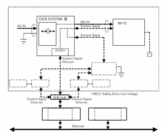
3.System Diagram
3.1Stand-alone System
Stand Alone System Block Diagram (Example)
Patient Environment or Medical room
|
SELV* |
|
|
|
|
50G Power |
|
40G COMPACT |
(7m) |
|
Imaging Unit |
Protective Grounding |
|
|
1st/2nd |
|
|
AC230V |
|
|
Insulation with |
|
|
reinforcement |
|
|
Basic Insulation
X-Ray Generator
(601 Compatible)
FC-E21A or
Recommendation General
PC
- 4 -
1.General
3.2Total System (CXDI-40G COMPACT + Plural Connection (Other Imaging Unit)
Total System Block (Example)
Patient Environment or Medical Room
50G Power
(7m)
Protective Grounding
1st/2nd
AC230V
Insulation with reinforcement
|
|
|
Basic Insulation |
|
Ready |
||
|
|
|
|
|
|
|
Lamp |
|
|
|
|
|
|
X-ray Generator |
|
|
|
|
|
|
|
601 Compatible |
|
CXDI-40E |
Power Box |
|
Power Box |
CXDI-50 |
|||
Sensor Unit |
|
Sensor Unit |
|||||
|
|
|
|
|
|||
|
|
|
|
|
|
|
|
|
|
|
General HUB |
|
|
||
|
|
|
|
|
|
|
|
|
|
|
FC-E21A or |
|
Image examination WS |
|
|
|
|
Recommendation General |
|
Image File Equipment |
|
||
|
|
|
PC |
|
Printer etc |
|
|
|
|
|
|
|
|
|
|
- 5 -

1.General
4.CXDI Image Processing
4.1 Processing Flow
Born image |
|
Offset correction |
|
|
|
|
|
|
|
|
|
Correction |
Gain correction |
|
|
processing |
|
|
|
|
|
|
|
Raw image |
|
Defect correction |
dtstore |
|
|
|
|
Pre |
|
|
|
processing |
Sensitivity correction |
|
|
|
|
|
|
Original image |
|
|
|
|
QA processing |
|
|
|
|
|
|
|
|
Characteristic extraction |
|
QA image |
|
||
|
|
|
|
|
|
|
|
DICOM output |
: Gradation processing |
|
|
|
|
: Sharpening |
|
Diag. image |
|
: DEP |
|
|
|
: MTF enhancement |
|
|
|
|
|
|
|
(Frequency enhancement) |
|
|
|
: Grid stripe reduction |
|
Processed image |
|
|
|
|
: High density clipping request |
||
|
|
||
- 6 -
1. General
4.2Image Types
(1)Born image
The image obtained with LANMIT before any correction is made.
Outside distribution of these images is prohibited, including dtstore images.
(2) Raw image
Born image after offset processing, gain correction.
This is the image with LANMIT specific characteristics corrected.
(3) Original image
Raw image after preprocessing.
(4) QA image
Original image after gradation processing, sharpening, and other processing. The CXDI performs image processing up to this point.
(5) Diagnosis image
QA image after further image processing necessary for diagnosis. Image processed by the user for diagnostic purposes.
(6) Processing image
Diagnosis image after post-processing.
Image modified by the user or the default processed image.
- 7 -
1. General
5. Specifications
The CXDI-40G COMPACT has a secondary scanning drive unit, data reading unit, and A/D conversion unit on one side of the LANMIT, and it is a sensor unit that reads image data from one direction for a single panel.
The X-ray image is converted to photoelectric signals by the sensor unit, and the scanned electrical signals (image signals) undergo A/D conversion, pass through the power box, and are transferred to the control PC over an Ethernet cable.
|
|
Item |
|
|
40G COMPACT |
|
|
Remarks |
|
||
|
|
|
|
|
|
|
|
|
|
|
|
|
Operational format |
|
|
Upright stand, table, universal stand |
|
Installation on a motor vehicle |
|||||
|
|
|
|
is not possible. |
|
|
|
||||
|
|
|
|
|
|
|
|
|
|
||
|
Effective exposure range |
430 x 430 mm |
|
|
|
|
|
|
|||
|
|
|
|
|
|
|
|
|
|
||
|
Total number of pixels |
|
2706 x 2700 pixels |
|
|
|
|
|
|
||
|
|
|
|
|
|
|
|
|
|
||
|
Number of effective pixels |
|
7.2 million (2688 x 2688 pixels) |
|
|
|
|
|
|
||
|
|
|
|
|
|
|
|
|
|
|
|
|
Pixel pitch |
|
|
160 µm x 160 µm |
|
|
|
|
|
|
|
|
|
|
|
|
|
|
|
|
|||
|
Fluorescent substance |
|
|
GOS |
|
LANMIT sensor |
|
|
|||
|
|
|
|
|
|
|
|
|
|
|
|
|
Sensor sensitivity |
|
|
Same as CXDI-40EG |
|
|
|
|
|
|
|
|
|
|
|
|
|
|
|
|
|
|
|
|
Exposure time |
|
|
0 ms to 1 sec., 1 to 3 sec. |
|
|
|
|
|
|
|
|
|
|
|
|
|
|
|
|
|
||
|
Output gradations |
|
12 bits (4096 gradations), A/D 14 bits |
|
|
|
|
|
|
||
|
|
|
|
|
|
|
|
|
|
|
|
|
Transfer method |
|
|
Ethernet between sensor unit and PC (via |
|
|
|
|
|
|
|
|
|
|
power box) |
|
|
|
|
|
|
||
|
|
|
|
|
|
|
|
|
|
|
|
|
Preview time |
|
Approx. 3 sec |
|
|
|
|
|
|
||
|
|
|
|
|
|
|
|
|
|
|
|
|
Exposure cycle time |
|
|
15 sec. (typ.) |
|
|
|
|
|
|
|
|
|
|
|
|
|
|
|
|
|
||
|
External |
dimensions |
(Sensor |
|
470(W)×548(L)×32(H) mm |
|
Not |
including |
insulation |
||
|
unit) |
|
|
|
|
|
sheet |
|
|
|
|
|
External |
dimensions |
(Power |
|
358(W)×212(L)×75(H) mm |
|
|
|
|
|
|
|
box) |
|
|
|
|
|
|
|
|
|
|
|
Color of sensor unit exterior |
|
Black (Cathodic electrodeposition coating) |
|
|
|
|
|
|
||
|
|
|
|
|
|
|
|
|
|
|
|
|
Mass (Sensor unit) |
|
|
11.0 kg |
|
Not |
including |
cables |
or |
||
|
|
|
|
ready lamp |
|
|
|
||||
|
|
|
|
|
|
|
|
|
|
||
|
Mass (Power box) |
|
|
4.2 kg |
|
|
|
|
|
|
|
|
|
|
|
|
|
|
|
|
|
||
|
Distance from exterior CFRP |
|
6.6±0.5 mm |
|
|
|
|
|
|
||
|
surface to sensor surface (glass |
|
|
|
|
|
|
|
|||
|
surface) |
|
|
|
|
|
|
|
|
|
|
|
Patient contact surface |
|
None |
|
|
|
|
|
|
||
|
|
|
|
|
|
|
|
||||
|
Exterior |
strength |
(imaging |
|
Excess local weight: 12 kg (118 N) with |
|
Incoming X-ray surface |
||||
|
unit) |
|
|
|
15 mm diameter for 1 minute |
|
only |
|
|
|
|
|
Exterior strength (imaging |
|
Excess local weight: 20 kg (196 N) with |
|
Locations |
other |
than |
||||
|
unit, power box) |
|
|
15 mm diameter for 1 minute |
|
incoming X-ray surface |
|
||||
- 8 -
1. General
|
Item |
|
|
40G COMPACT |
|
|
|
Remarks |
|
||||
|
|
|
|
|
|
|
|
|
|
|
|
|
|
|
Drop |
|
Not applicable |
|
|
|
|
|
|
|
|
|
|
|
|
|
|
|
|
|
|
|
|
|
|
|
|
|
Water-proofing |
|
Not applicable |
|
|
|
|
|
|
|
|
|
|
|
|
|
|
|
|
|
|
|
|
|
|
|
|
|
Resistance to chemicals |
|
Not applicable |
|
|
|
|
|
|
|
|
|
|
|
|
|
|
|
|
|
|
|
|
|
|
||
|
IC X-ray protection |
No protective lead |
|
|
|
|
|
|
|
|
|
||
|
|
|
|
|
|
|
|
|
|
|
|
||
|
Back-scattering prevention |
Not considered |
|
|
|
|
|
|
|
|
|
||
|
|
|
|
|
|
|
|
|
|
|
|
||
|
|
|
|
*The imaging unit can be installed to a |
|
Imaging |
unit |
securing |
|||||
|
|
|
|
|
components |
are |
obtained |
||||||
|
|
|
|
Bucky unit, stand or table. |
|
|
|
from the respective dealer. |
|||||
|
Imaging unit installation |
|
*The imaging unit can be installed without |
|
The attachment |
of |
the |
||||||
|
|
|
|
modification to the Liebel-Flarsheim |
|
imaging unit uses M5 screw |
|||||||
|
|
|
|
Bucky unit and compatible Bucky units. |
|
holes (10 locations) in the |
|||||||
|
|
|
|
|
|
|
|
|
imaging unit. |
|
|
|
|
|
|
|
|
*Fixed grid |
|
|
|
|
Grid and the grid securing |
||||
|
|
|
|
*Installation inside imaging unit is not |
|
||||||||
|
Grid |
|
|
possible |
|
|
|
|
components |
are |
obtained |
||
|
|
|
|
*Installed in a Bucky unit, stand or table. |
|
from the respective dealer. |
|||||||
|
|
|
|
*Same specifications as 40EG grid |
|
|
|
|
|
|
|
||
|
Grid attachment/removal |
|
Can be performed |
by service staff |
only. |
|
|
|
|
|
|
||
|
|
Cannot be performed by users. |
|
|
|
|
|
|
|
||||
|
|
|
|
|
|
|
|
|
|
|
|||
|
|
|
|
*Installation inside imaging unit is not |
|
|
|
|
|
|
|||
|
|
|
|
possible |
|
|
|
|
Phototimer |
and |
the |
||
|
Phototimer |
|
|
*Installed in a Bucky unit, stand or table. |
|
phototimer |
|
securing |
|||||
|
|
|
*Except for the external dimensions, the |
|
components |
are |
obtained |
||||||
|
|
|
|
|
|||||||||
|
|
|
|
specifications are identical to the 40EG |
|
from the respective dealer. |
|||||||
|
|
|
|
phototimer |
|
|
|
|
|
|
|
|
|
|
Calibration |
|
|
Can be performed |
by service staff |
only. |
|
Users |
can |
conduct |
a |
||
|
|
|
Cannot be performed by users. |
|
|
self-diagnostic test. |
|
|
|||||
|
|
|
|
|
|
|
|
||||||
|
Environmental |
friendliness |
|
Supported |
|
|
|
|
|
|
|
|
|
|
(RoHS supported) |
|
|
|
|
|
|
|
|
|
|
|
|
|
Compatible control PC |
|
*FC-E21A for CXDI Control Station |
|
|
|
|
|
|
|
|||
|
|
*General-purpose |
PC |
with |
same |
|
|
|
|
|
|
||
|
|
|
|
performance as FC-E21A |
|
|
|
|
|
|
|
|
|
|
Compatible operating system |
Windows XP SP3 (or SP2) |
|
|
|
|
|
|
|
|
|||
|
|
|
|
|
|
|
|
|
|
|
|
||
|
Power ON/OFF control |
None |
|
|
|
|
|
|
|
|
|
||
|
|
|
|
|
|
|
|
|
|
||||
|
Stand |
|
Dedicated stand, table or universal stand |
|
|
|
|
|
|
||||
|
|
|
|
|
|
|
|
|
|
|
|||
|
|
|
|
*Up to four units can be connected to a |
|
|
|
|
|
|
|||
|
|
|
|
single control PC (using a hub) |
|
|
|
|
|
|
|
||
|
Connectability |
|
|
*Up to three identical imaging units are |
|
|
|
|
|
|
|||
|
|
|
|
possible |
|
|
|
|
|
|
|
|
|
|
|
|
|
*Imaging unit and power box are paired |
|
|
|
|
|
|
|||
|
X-ray exposure delay |
|
Less than 0.3 sec. |
|
|
|
|
|
|
|
|
|
|
|
|
|
|
|
|
|
|
|
|
|
|
||
|
Exposure preparation time |
|
Normal exposure mode: 10 sec. |
|
|
|
|
|
|
|
|||
|
|
Long time exposure mode: 30 sec. |
|
|
|
|
|
|
|
||||
|
|
|
|
|
|
|
|
|
|
|
|||
|
Full image preview time |
|
Approx. 12 sec. |
|
|
|
|
|
|
|
|
|
|
|
|
|
|
|
|
|
|
|
|
||||
|
Exposure cycle time |
|
15 sec. or less in normal exposure mode |
|
|
|
|
|
|
||||
|
|
|
|
|
|
|
|
|
|
|
|
|
|
|
System control unit |
|
|
Control PC, power box |
|
|
|
|
|
|
|
|
|
|
|
|
|
|
|
|
|
|
|
|
|
|
|
- 9 -
1. General
|
Item |
|
40G COMPACT |
|
Remarks |
|
|
|
|
|
|
|
Sensor DC/DC power supply |
|
Inside power box |
|
|
|
|
|
|
|
|
|
Sensor cable |
Overall length of 7 meters, one type |
|
|
|
|
|
|
|
|
|
|
X-ray monitor |
|
None |
|
|
|
|
|
|
|
|
|
Grid detection |
None |
|
|
|
|
|
|
|
|
|
|
Remote switch |
|
None |
|
|
|
|
|
|
|
|
|
Imaging unit status display |
External ready lamp |
|
|
|
|
|
|
|
|
|
|
Temperature sensor |
|
Included (error when temperature exceeds |
|
|
|
|
49°C) |
|
|
|
|
|
|
|
|
|
|
Power consumption (when one |
|
Approx. (17) W |
Sleep mode/Standby mode |
|
|
unit is connected) |
|
|
|
|
|
Heat generation |
|
Approx. 35 kcal/h |
|
15-sec. exposure cycle time |
|
|
|
|
|
|
|
|
Approx. 15 kcal/h |
|
During sleep, standby |
|
|
|
|
|
||
|
|
|
|
|
|
|
Environmental conditions |
|
|
|
|
|
1) Transportation and storage |
|
|
|
|
|
Temperature |
|
–30 to +60°C |
|
|
|
|
|
|
|
|
|
Humidity |
10% to 60% (no condensation) |
|
|
|
|
|
|
|
|
|
|
Atmospheric pressure |
|
700 to 1060 hPa |
|
|
|
|
|
|
|
|
|
2) Operating environment |
|
|
|
|
|
|
|
|
|
|
|
Temperature |
+10 to +35°C |
|
|
|
|
|
|
|
|
|
|
Humidity |
30% to 75% (no condensation) |
|
|
|
|
|
|
|
|
|
|
Atmospheric pressure |
|
700 to 1060 hPa |
|
|
|
|
|
|
|
|
|
|
|
|
|
|
- 10 -

Printed by Canon
Feb. 2009 Rev. 01
CXDI-40G COMPACT
2. Installation
Canon Inc. Japan
Copyright(C) Canon Inc. Medical Technical Service Dept. All rights reserved.
|
CONTENTS |
|
1. Caution............................................................................................................................ |
1 |
|
1.1 |
Caution during Operating........................................................................................ |
1 |
1.2 |
Installation Restrictions........................................................................................... |
1 |
1.3 |
Installation Notes..................................................................................................... |
2 |
2. Unpacking and List of Materials .................................................................................... |
3 |
|
2.1 |
Packaging Diagram ................................................................................................. |
3 |
2.2 |
Product Configuration ............................................................................................. |
5 |
3 Installation Procedure ...................................................................................................... |
8 |
|
3.1 |
Required Tool.......................................................................................................... |
8 |
3.2 |
System Installation Procedure................................................................................. |
9 |
4. Connection to Units ........................................................................................................ |
11 |
|
4.1CXDI-40G COMPACT Instalation Flowchart......................................................... |
11 |
|
4.2 |
Affixing the Insulation Sheets................................................................................. |
12 |
4.3 |
Attaching the Sensor Cable and Ready Lamp Cable............................................... |
15 |
4.4 |
Connecting to the Power Box.................................................................................. |
19 |
4.5 |
Connection Diagram for Control PC Rear Panel .................................................... |
23 |
4.6 |
Imaging Unit Securing Screws................................................................................ |
24 |
5. Adjusting the Alignment................................................................................................. |
25 |
|
5.1Overview .................................................................................................................. |
25 |
|
5.2 |
Tools........................................................................................................................ |
25 |
5.3 |
Adjustment .............................................................................................................. |
25 |
5.3.1. Stand................................................................................................................. |
25 |
|
5.3.2. Table................................................................................................................. |
28 |
|
6. Installing the Phototimer................................................................................................. |
31 |
|
6.1 |
Overview ................................................................................................................. |
31 |
6.2 |
Notes ....................................................................................................................... |
31 |
7.Starting up and Shutting Down the System ..................................................................... |
33 |
|
8. X-ray Controller Interface .............................................................................................. |
34 |
|
8.1 |
Interface Signal Description.................................................................................... |
34 |
8.2 |
When Normal Imaging............................................................................................ |
35 |
8.3 |
When Timeout due to RX_REQ not Negating........................................................ |
36 |
8.4 |
Signal Names and Functions in the Connection with the X-ray Generator............. |
37 |
8.5 |
The Connection with X-ray Generator Equipment ................................................. |
38 |
8.6 |
Rating and Characteristics for Relay and Photo Coupler........................................ |
39 |
9. Network Settings ............................................................................................................ |
41 |
|
9.1. Overview ................................................................................................................ |
41 |
|
9.2. Preparation ............................................................................................................. |
41 |
|
9.3. Setup Method ......................................................................................................... |
41 |
|
9.3.1. TCP/IP Setting for the Control PC Network Card ........................................... |
41 |
|
9.3.2. Network Setting for Screwcap.ini .................................................................... |
42 |
|
9.3.3. Network Setting Stored in Imaging Unit.......................................................... |
43 |
|
9.3.4. Connection Setup for a Multiple Number of Sensor Units .............................. |
44 |
|
|
9.3.4.1. General Flow for Setup Procedure ............................................................. |
44 |
|
9.3.4.2. Detailed Setup Procedures.......................................................................... |
45 |
10.Adjusting the Photo Timer............................................................................................. |
46 |
|
10.1. Overview .............................................................................................................. |
46 |
|
10.2. Preparation ........................................................................................................... |
46 |
|
10.3. Adjustment ........................................................................................................... |
47 |
|
11. Setting the Fixed ROI Area .......................................................................................... |
48 |
|
12. Settings ......................................................................................................................... |
51 |
|
12.1 Checking and Setting the Date and Time .............................................................. |
51 |
|
12.2 Checking the Firmware Version............................................................................ |
52 |
|
12.3 Installing Firmware and PLD Code....................................................................... |
54 |
|
12.4 Checking the Sensor Serial No.............................................................................. |
55 |
|
12.5 Set Up Startup Menu ............................................................................................. |
56 |
|
12.6 Identifying the Sensor Units .................................................................................. |
59 |
|
12.7 Entering Control PC Serial Number ...................................................................... |
60 |
|
12.8 Table Setup Settings .............................................................................................. |
61 |
|
12.9 Performing the Annotation Settings ...................................................................... |
62 |
|
12.10 |
Network Connections.......................................................................................... |
63 |
12.11 |
Linearity Check of Transfer Image Density........................................................ |
88 |
12.12 |
Operation Unit Gamma Correction ..................................................................... |
96 |
12.13 |
Changing the Total Image Count ........................................................................ |
99 |
12.14 |
Backing Up When Installing ............................................................................... |
101 |
12.15 |
Backing up Setting Data to FD ........................................................................... |
102 |
12.16 |
Tool Modes (/np mode)....................................................................................... |
104 |
13. Installing the Grid ......................................................................................................... |
107 |
|
13.1 Overview ............................................................................................................... |
107 |
|
13.2 Notes...................................................................................................................... |
107 |
|
13.3 Checking the Grid Angular Misalignment ............................................................ |
107 |
|
14. Image Quality ............................................................................................................... |
110 |
|
15. Post-installation Checks................................................................................................ |
112 |
|
16. Dimensional Drawing ................................................................................................... |
114 |
|
16.1 CXDI-40G COMPACT Imaging Unit .................................................................. |
114 |
|
16.2 Power Box............................................................................................................. |
115 |
|
18.4 Ready Lamp Unit .................................................................................................. |
116 |
|
2. Installation
1. Caution
1.1 Caution during Operating
Please pay attention to the following points when installing the equipment.
(1) If the equipment is hoisted, lowered or transported, it must be supported at both sides by a minimum of two people so there is no danger of it falling.
(2) When transporting the equipment with a forklift, lower the load to the lowest possible position that does not impede the running of the forklift.
(3)When installing the equipment, be sure the site meets the following criteria:
1)There must be no dripping water in the area.
2)The environment must be free of harmful elements, such as humid or acidic air, air with a saline or sulfur content, where there is poor ventilation, or where air pressure or temperature is abnormal.
3)The equipment must not be placed at an angle or subjected to vibration or shock (this includes during transportation).
4)The equipment must not be kept where chemical products are stored or where gasses are generated.
5)The site’s power supply must be of the correct voltage and frequency for the equipment.
6)The site must be connected to a fully earthed cable with sufficient ground resistance to meet standard values.
(4)After installation, be sure to dispose of waste product packaging with care and with full respect for the environment.
(5)As the imaging unit is easily portable, take special care that it is not knocked, dropped or subjected to strong shocks.
1.2Installation Restrictions
(1)Install so that the distance between the imaging unit and power box is at least 300 mm from the imaging unit sides (in four directions) and at least 150 mm from locations other than the imaging unit sides.
(2)Except for the sensor cable connected to the imaging unit and the cable for the ready lamp unit, the cables must not be used with moving parts.
(3)Before starting the installation work, discharge any static charge that has built up on your body. Also, be sure that the static charge has been discharged before touching (removing) the PCBs and cable connectors.
(4)Install the imaging unit, grid, and phototimer to a Bucky unit, stand or table. The parts that secure the imaging unit, grid, and phototimer are obtained from the distributor.
(5)Do not remove the imaging unit from the Bucky unit, stand or table for cassette-type portable usage.
-1 -
2.Installation
(6)The patient must not directly touch the imaging unit when taking exposures.
(7)Do not install on a motor vehicle.
1.3Installation Notes
(1)Noise and artifacts tend to appear on the image in environments with strong electromagnetic fields. Therefore, try to select an installation location that is not near electronic devices.
Examples of applicable devices:
CRT monitors, X-ray generators, medical electronic devices
(2)Before starting the installation work, discharge any electrostatic charge that has accumulated on your body.
(3)Calibration imaging can be performed by service staff only. It cannot be performed by users.
(4)Do not perform calibration imaging with the grid installed.
Except for grid, phototimer and other parts that are located in the X-ray entrance surface must be installed when calibration imaging is performed.
(5)After installing the imaging unit in the Bucky unit, stand or table, if the user cannot confirm the cross lines of the imaging unit surface, attach an indicator mark after adjusting the X-ray tube position if necessary.
(6)Routing of the cables for the table, upright stand, and universal stand is based on the table, upright stand, and universal stand specifications. However, the bending radius R of the cable (radius of inner cable circumference) is based on the following conditions that incorporate the bending durability and other factors.
R at stationary parts (radius of cable inner circumference) = 25 mm or more
R at moving parts (radius of cable inner circumference) = 50 mm or more
Do not forcibly bend, fold over, or pull out the cable, and secure the cable so that no excessive loads are applied to it in any state.
(7)Install so that there is sufficient space for maintenance and other work. Imaging unit dimensions: 470 (W)×548 (L)×32 (H) mm
(8)Do not apply load of over 12kg(118N) to the X-ray entrance surface of the imaging unit outer cover.
- 2 -

2.Installation
2.Unpacking and List of Materials
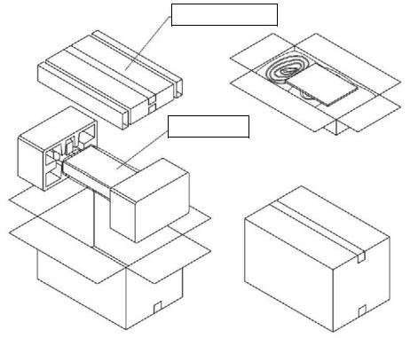
2.1 Packaging Diagram
1) CXDI 40G COMPACT Sensor Unit Assembly Packaging
Accessories Box
CXDI 40G COMPACT
Imaging Unit
- 3 -
2. Installation
2) CXDI SYSTEM III Assembly Packaging
Accessories Box
Power Box
- 4 -
2. Installation
2.2 Product Configuration
(1)Product Configuration List
1)CXDI-40G COMPACT
No. |
Item Name |
Qty |
Remarks |
|
1 |
CXDI-40G COMPACT Imaging Unit |
1 |
|
|
2 |
Sensor cable |
1 |
7m |
|
3 |
Ready lamp |
1 |
|
|
4 |
Ready lamp mounting shaft |
1 |
|
|
5 |
Insulation sheet |
16 |
|
|
6 |
Cable tie |
3 |
|
|
7 |
Screw (M3x8mm) |
4 |
|
|
8 |
Operation manual (For imaging unit) |
- |
|
|
9 |
Attached documents for medical |
- |
(JPN) |
|
10 |
Warranty registration |
- |
(JPN) |
|
11 |
Warranty card |
- |
(US) |
|
12 |
Safety Booklet for German (WEEE |
- |
(EU) |
|
directive) |
||||
|
|
|
||
13 |
Installation Report |
- |
(US/EU) |
|
2) CXDI SYSTEM III |
|
|
||
No. |
Item Name |
Qty |
Remarks |
|
1 |
Power Box |
1 |
|
|
2 |
X-ray I/F cable |
1 |
20m |
|
3 |
Power supply cable (with AC plug) |
1 |
3m (100/120/230V) |
|
4 |
Cable clamp |
1 |
|
|
5 |
Screw (M4x6mm) |
1 |
|
|
6 |
Operation manual (Power box) |
- |
|
|
LAN cable for connecting Control PC / Power Box and Network switch (Switching HUB) for connecting the multiple Imaging Units shall be procured at each sales company.
- LAN cable (Over category 5)
Recommended length of the cable is 30m or less.
When Control PC and Power Box are connected directly, Cross type is used, but when they are connected via Network switch, Straight type is used. However, this is not applied when Network switch has AUTO-MDI/MDI-X function*.
- Network switch (Switching HUB)
Sales companies adopt Network switch (Switching HUB) after conducting the test and the operation check for Switching HUB that meets the general standard.
- 5 -

2. Installation
(2) Configuration
- CXDI-40G COMPACT
No. |
1 |
No. |
2 |
Name |
Imaging Unit |
Name |
Sensor Cable |
Qty |
1 |
Qty |
1 |
Remarks |
|
Remarks |
Imaging Unit / Power Box |
|
|
|
|
No. |
3 |
No. |
4 |
Name |
Ready lamp unit |
Name |
Ready lamp mounting shaft |
Qty |
1 |
Qty |
1 |
Remarks |
|
Remarks |
|
|
|
|
|
No. |
5 |
No. |
6 |
Name |
Insulation sheet |
Name |
Cable tie |
Qty |
16 |
Qty |
3 |
Remarks |
t =0.4mm |
Remarks |
|
|
|
|
|
- 6 -

2. Installation
- CXDI-CXDI SYSTEM III
No. |
1 |
No. |
2 |
Name |
Power box |
Name |
X-ray I/F cable |
Qty |
1 |
Qty |
1 |
Remarks |
I/F and Power Supply |
Remarks |
To connect with X-ray generator |
|
|
|
|
No. |
3 |
No. |
4 |
Name |
Power supply cable |
Name |
Cable clamp |
Qty |
1 |
Qty |
1 |
Remarks |
For Power Box (100/120/230V) |
Remarks |
|
|
|
|
|
No. |
|
No. |
|
Name |
|
Name |
|
Qty |
|
Qty |
|
Remarks |
|
Remarks |
|
|
|
|
|
- 7 -
2. Installation
3 Installation Procedure
3.1 Required Tool
No. |
Tools name |
Qty |
Remarks |
|
|
|
|
|
|
1 |
General tools |
1 set |
JIS Screw Driver Set |
|
|
|
|
|
|
2 |
Laptop PC |
1 |
PC/AT compatible |
|
(OS: Windows XP) |
||||
|
|
|
||
3 |
LAN card |
1 |
For laptop PC (If necessary) |
|
|
|
|
|
|
4 |
Mouse |
1 |
PS/2 type |
|
|
|
|
|
|
5 |
Keyboard |
1 |
PS/2 type |
|
|
|
|
|
|
6 |
Hub |
1 |
For connection between control PC |
|
and Laptop PC |
||||
|
|
|
||
|
|
|
Straight type |
|
7 |
10/100 BASE-Tx cable |
2 |
(For connection between Laptop PC |
|
|
|
|
and control PC) |
|
8 |
Software for |
1 |
BY9-6538-XXX (Check the version of the |
|
service maintenance |
software) |
|||
|
|
|||
9 |
CXDI application and firmware |
1 |
|
|
|
|
|
|
|
10 |
CXDI software |
1 |
|
|
version compatibility table |
|
|||
|
|
|
||
11 |
Mirror, oil-based marker, etc. |
1 |
For adjusting the alignment with the X-ray |
|
tube |
||||
|
|
|
||
12 |
Tester |
1 |
Used to verify the electrical isolation between |
|
the Bucky unit (stand or table) and imaging |
||||
|
|
|
unit |
|
|
|
|
|
|
|
|
|
|
- 8 -
2.Installation
3.2System Installation Procedure
No. |
Step |
Conditions and checkpoints |
Reference |
|
|
|
|
1 |
Unpack and check the |
- There are no missing parts, damage, |
|
product’s constituent parts |
scratches, or other imperfections. |
|
|
|
|
||
|
Affix the insulation sheets to |
- Affix to the specified locations on the |
|
2 |
the sensor unit |
imaging unit without making any raised or |
|
|
|
bent sections. |
|
|
Install the imaging unit |
- Install and secure in place in the Bucky unit, |
|
3 |
|
stand or table. Obtain the imaging unit |
|
|
fixture pieces from a distributor. |
|
|
|
|
|
|
|
|
- Be careful not to drop the imaging unit. |
|
|
Connect the imaging unit and |
- The cables must be routed so that no |
|
|
power box |
unreasonable loads are placed on them. |
|
4 |
|
- R at stationary parts (radius of cable inner |
|
|
circumference) = 25 mm or more |
|
|
|
|
|
|
|
|
- R at moving parts (radius of cable inner |
|
|
|
circumference) = 50 mm or more |
|
5 |
Connect the power box and the |
- The cables must be routed in such a way that |
|
control PC |
no unreasonable loads are brought to bear |
|
|
|
|
upon them. |
|
|
Attach and connect the |
- The cables must be routed in such a way that |
|
6 |
operation unit |
no unreasonable loads are brought to bear |
|
|
|
upon them. |
|
7 |
Adjust the alignment |
- Be careful not to scratch the imaging unit. |
|
|
|
|
|
|
|
|
|
8 |
Install the phototimer |
- Install in the Bucky unit, stand or table. |
|
|
- Be careful not to scratch the sensor. |
|
|
|
|
|
|
9 |
Start the system |
|
|
|
|
|
|
|
|
|
|
|
Identifying the imaging units |
|
“Identifying the |
10 |
and setting the number of units |
|
Sensor Unit” in |
to be connected (inputting the |
|
“Setting” |
|
|
|
||
|
sensor serial numbers) |
|
|
|
Install control PC unit serial |
|
“Entering |
11 |
number. |
|
Control PC |
|
|
Serial Number” |
|
|
|
|
|
|
|
|
in “Setting” |
|
Check the software program’s |
- The compatibility of the sensor unit and the |
“Checking the |
12 |
version |
control PC must be checked on the |
Firmware |
|
compatibility list, and the software program |
Version” in |
|
|
|
||
|
|
must be installed or upgraded as required. |
“Setting” |
|
Check date and time |
- Date and time must be changed according to |
“Checking and |
13 |
|
the area where the instrument is installed. |
Setting the Date |
|
|
|
and Time”. |
14 |
Connect the power box and |
- The manufacturer of the X-ray generators |
|
X-ray generators |
must be asked to handle the connections |
|
|
|
|
with the generators. |
|
15 |
Adjusting the timing with the |
- This is generally not necessary. |
|
X-ray generators |
|
|
|
|
|
|
|
|
Perform calibration imaging |
- No errors must be displayed. |
|
16 |
|
- Calibration imaging must be performed by |
|
|
|
service staff only. |
|
- 9 -
2. Installation
No. |
|
Step |
|
Conditions and checkpoints |
Reference |
||
|
|
|
|
||||
17 |
Set the Fixed ROI areas |
- If necessary, to set the ROI area. |
“Set the Fixed |
||||
|
|
|
|
ROI areas” |
|||
|
|
|
|
|
|||
18 |
Set exposure parameter table |
- Set it in consultation with the technician. |
“Table Setup |
||||
|
|
|
|
Setting” |
|
||
|
|
|
|
|
|
||
19 |
Set annotation |
|
- Set it in consultation with the technician. |
“Performing the |
|||
|
|
|
|
Annotation |
|||
|
|
|
|
|
Setting” |
|
|
20 |
Connect the network and set |
|
“Network |
|
|||
the output destination |
|
|
Connections” in |
||||
|
|
|
|
|
“Setting” |
|
|
|
Startup settings |
|
|
“Set Up Startup |
|||
21 |
|
|
|
|
Menu” in |
|
|
|
|
|
|
|
“Setting” |
|
|
|
Check the linearity of the |
|
“Linearity |
||||
|
transferred image density |
|
Check of |
|
|||
22 |
|
|
|
|
Transfer Image |
||
|
|
|
|
|
Density” in |
||
|
|
|
|
|
“Setting” |
|
|
|
Correct operation unit gamma |
|
“Operation Unit |
||||
23 |
|
|
|
|
Gamma |
|
|
|
|
|
|
Correction” in |
|||
|
|
|
|
|
|||
|
|
|
|
|
“Setting” |
|
|
|
Install the grid |
|
- Install in the Bucky unit, stand or table. |
|
|
|
|
24 |
|
|
|
- Check the grid installation angle. |
|
|
|
|
|
|
|
- Use as a fixed grid. |
|
|
|
25 |
Self-diagnostic testing |
|
- No errors must be displayed. |
|
|
|
|
|
|
|
|
|
|
|
|
|
|
|
|
|
|||
26 |
Radiographic testing |
|
- Check the image quality and transfer |
“Image Quality |
|||
|
|
|
operation to printer and storage. |
Check” |
|
||
|
|
|
|
|
|||
27 |
Body parts settings |
|
- The engineer in charge must be consulted |
Operation |
|
||
|
|
|
prior to performing these settings. |
Manual |
|
||
|
|
|
|
|
|||
28 |
Check and perform the system |
- The engineer in charge must be consulted |
“Setting” |
|
|||
settings |
|
|
prior to performing these settings. |
|
|||
|
|
|
|
|
|
||
|
Perform |
the |
overall |
- Check according to the check sheet. |
“Post |
|
|
29 |
adjustment |
and |
delete |
- Delete unneeded data. |
Installation |
||
unneeded data |
|
|
Check” in |
|
|||
|
|
|
|
||||
|
|
|
|
|
“Setting” |
|
|
30 |
Clean |
|
|
|
|
|
|
|
|
|
|
|
|
|
|
|
|
|
|
|
|||
31 |
Explain operation to the user |
|
Operation |
|
|||
|
|
|
|
Manual |
|
||
|
|
|
|
|
|
||
|
Adjust final parameters |
|
- The engineer in charge must be consulted |
Operation |
|
||
32 |
|
|
|
prior to narrowing down the adjustments to |
|
||
|
|
|
Manual |
|
|||
|
|
|
|
the final values. |
|
||
|
|
|
|
|
|
|
|
|
Backing up valuable data |
- Back up when setting, and back up the |
“Backing |
Up |
|||
|
|
|
|
setting data to FD. |
when |
Setting” |
|
33 |
|
|
|
|
and |
“Backing |
|
|
|
|
|
Up Setting Data |
|||
|
|
|
|
|
|||
|
|
|
|
|
to |
FD” |
in |
|
|
|
|
|
“Setting” |
|
|
- 10 -
Loading...