


OPERATING AND INSTALLATION MANUAL
CONVERTER
SE 56

SE 56
 INDEX
INDEX
qIntroduction ________________________________________________________________________________pag.3
§ Symbol Used on the manual________________________________________________________________pag.3
qTechnical characteristics _____________________________________________________________________pag.4
§ Electrical characteristics ___________________________________________________________________pag.4 § Environmental conditions of use ____________________________________________________________pag.4 § Operative temperature ____________________________________________________________________pag.4
§Overall dimensions _______________________________________________________________________pag.5
Electrical connections ________________________________________________________________________pag.6 § Grounding instructions ____________________________________________________________________pag.6 § Power supply converter ___________________________________________________________________pag.6 § Terminal block M1 for compact, separate and panel version ______________________________________pag.7 § Electrical connections sensor-converter _______________________________________________________pag.8
qInputs/outputs ______________________________________________________________________________pag.9
§ Expansion modules (no rele module)________________________________________________________ pag.10 § Expansion modules (rele module) __________________________________________________________ pag.11 § Digital Input ___________________________________________________________________________ pag.12 § On/Off output wiring (up to 1250 Hz) - low frequency __________________________________________ pag.15 § On/Off output wiring (up to 12500 Hz) - high frequency ________________________________________ pag.15 § Analogical output - 0\4÷20 mA____________________________________________________________ pag.15
qStart up and maintenance of the instruments _________________________________________________ pag.16
qHow to access at the instrument functions ____________________________________________________ pag.17
§ Converter visualization pages _____________________________________________________________ pag.17 § Converter visualization pages with currency enable ____________________________________________ pag.17 § Flags interpretation and led _______________________________________________________________ pag.18
§Converter key board _____________________________________________________________________ pag.19
§ Converters menues _____________________________________________________________________ pag.20
§Functions description ____________________________________________________________________ pag.21
§ Access codes ___________________________________________________________________________ pag.24 § Block levels ____________________________________________________________________________ pag.26 § Access the configuration menu_____________________________________________________________ pag.26
qProgramming functions _____________________________________________________________________ pag.27
qBatch ______________________________________________________________________________________ pag.35
§ Enable batch ___________________________________________________________________________ pag.35 § Programming batch______________________________________________________________________ pag.35
§Start / stop batch _______________________________________________________________________ pag.36
§Important notes ________________________________________________________________________ pag.36
qAlarm messages ___________________________________________________________________________ pag.37
§Causes and actions to be taken ____________________________________________________________ pag.37
§Anomalies codes _______________________________________________________________________ pag.37
APPENDIX 1
qDisplay rotation ______________________________________________________________________________ pag.38
2 |
|
210_EN_BU_4_3_5X.d |
|
||
|
|
oc |
SE 56
INTRODUCTION
This manual is integral part of the product. Read carefully the instructions contained since they give important indications for the safe use and maintenance.
Technical information and relative products in this manual could undergo modifications without any previous notice.
The flow meter must be used for what it has been built for. The improper use, possible tampering of the instrument or parts of it and substitutions of any not original components, make the warranty to decay automatically.
The manufacturer is considered responsible only if the instrument it’s used in his original configuration.
Reproduction of the present manual and of any possible software supplied with the instrument is strictly forbidden.
Symbols Used in the manual


 ATTENTION


 DANGER ELECTRIC SHOCK

 WARNING


 PRECAUTIONS
3 |
|
210_EN_BU_4_3_5X.d |
|
||
|
|
oc |
SE 56
TECHNICAL CHARACTERISTICS
ELECTRIC CHARACTERISTICS
Classification of the instrument: class I, IP 67, category of installation II
Power supply |
Power supply |
Power supply |
|
Pmax |
current |
|||
|
|
|
versions |
voltage |
frequency |
|
max |
|
|
|
|
|
|
||||
|
|
|
HV |
90÷265 Vac |
44÷66 Hz |
|
20W/25VA |
0,25 A |
|
|
|
LV |
18÷45 Vac/dc |
0-44÷66 Hz |
|
20W/25VA |
1,6 A |
|
|
|
LLV |
10÷35 Vdc |
|
|
20 W |
1,5 A |
|
|
|
|
|
|
|
|
|
|
|
|
|
|
|
|
|
|
INPUT/OUTPUT ISOLATION
 Input/output are insulated up to 500V
q The output 4÷20 mA and the output 24 Vdc are electrically connected


 ENVIRONMENTAL CONDITIONS OF USE
 The instrument can be installed inside or outside buildings
 Altitude: from –200 a 6000 m (from -656 to 19685 feet)
 Humidity range: 0÷100% (IP 67)
q Line voltage range: (see table on technical characteristics)
OPERATING TEMPERATURE
CONVERTER
Ambient Temp.
Min. |
Max |
||
°C |
°F |
°C |
°F |
-20* |
-4* |
60 |
140 |
* For discontinuous use, the installation of a heating resistance is necessary
4 |
|
210_EN_BU_4_3_5X.d |
|
||
|
|
oc |
SE 56
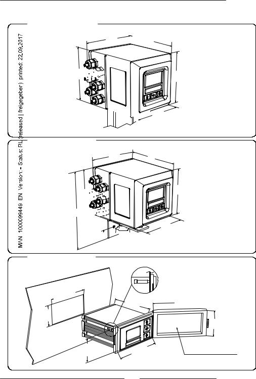
OVERALL DIEMENSIONS
COMPACT VERSION
146
146 


 170
170
138

 138
138
SEPARATE VERSION
146
170
146 


 230
230 


25 

PANEL VERSION
138
138
.0  137
137
|
145. |
0 |
0 |
. |
|
67 |
|
72.0 |
144 |
|
.0 |
5
160.0
0 . 80
IP65 (OPTIONAL)
210_EN_BU_4_3_5X.d oc

SE 56
GROUNDING INSTRUCTIONS
For the correct operation of the meter it’s NECESSARY that sensor and liquid are equipotential, so ALWAYS connect sensor and converter to the ground
|
|
CONVERTER POWER SUPPLY |
|
Wall version |
q Before connecting the power supply, verify that |
||
the mains voltage falls between the limits |
|||
|
|
||
|
|
indicated on the tag plate |
|
|
|
q ATTENTION: the converters on dc power |
|
|
M3 |
supply line are not protected against the |
|
|
inversions of polarity. |
||
L |
N |
q For the wiring use only approved conductors, |
|
with fireproof properties. |
|||
(+) |
(-) |
||
q The power supply line must be equipped with |
|||
|
|
||
Panel version |
an external protection for current overload (fuse |
||
|
|
or automatic line breaker with limiting capacity |
|
|
|
not greater than 10 A). |
|
|
|
q In the proximity of the instrument Provide a |
|
M3 |
|
circuit breaker that must be easily accessible |
|
|
from the operator and clearly identified. |
||
|
|
|
|
|
|
|
|
L |
N |
|
|
|
NOTE: characteristics of meter’s power supply, see |
||
(+) |
(-) |
|
|
|
|
||
|
|
|
|||||
page 4
6 |
|
210_EN_BU_4_3_5X.d |
|
||
|
|
oc |
SE 56
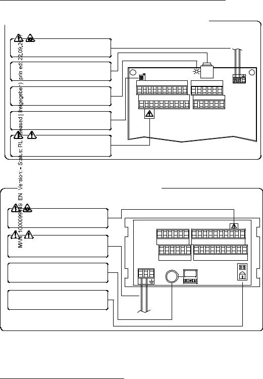
ELECTRICAL CONNECTIONS
 TERMINAL BLOCK M1 FOR COMPACT/SEPARATE VERSIONS
Power supply
IF2 socket
Signalling LED with light: interpretation at page 18
Dip switch for block levels enabling
Dangerous voltage on block 12-13:
-60 Vdc Max
-250 V Max on commutation coils
LOCK |
|
|
|
|
|
|
|
|
|
|
1 |
2 |
3 |
4 |
5 |
6 |
7 |
8 |
9 |
10 |
21 22 23 24 25 26 |
|
|
|
|
|
|
|
|
|
|
M3 |
11 12 13 14 15 16 17 18 19 20 |
27 28 29 30 31 32 |
|||||||||
|
||||||||||
|
|
|
|
M1 |
|
|
|
|
|
M2 |
TERMINAL BLOCK M1 FOR PANEL VERSIONS
Power supply
Dangerous voltage on blocks 12-13:
-60 Vdc Max
-250 V Max on commutation coils
IF2 socket
Dip switch for block levels enabling
M2 |
|
M1 |
|
|
|
|
|
|
|
|
26 25 24 23 22 21 |
20 19 |
18 17 16 15 14 13 12 11 |
||||||||
32 31 30 29 28 27 |
10 |
9 |
8 |
7 |
6 |
5 |
4 |
3 |
2 |
1 |
M3 |
|
|
|
|
|
|
|
|
|
|
7 |
|
210_EN_BU_4_3_5X.d |
|
||
|
|
oc |

SE 56
ELECTRICAL CONNECTIONS SENSOR TO CONVERTER
SEPARATE VERSION |
TERMINAL BLOCK M1 |
C015 |
1 |
E1 |
|
2 |
E2 |
||
|
|||
|
3 |
C |
|
|
4 |
SH |
|
|
11 |
SH |
|
|
12 |
B1 |
C016  13
13

 B2
B2
Sudden movements of the electrodes cable, can cause noises on measure
Max length of cable: m 20
ELECTRODES |
INPUT |
RS485 |
4-20mA |
|||
E1 E2 C SH |
+ |
- |
B |
A |
+ |
- |

 1
1 

 2
2 

 3
3 

 4
4 

 5
5 

 6
6 

 7
7 

 8
8 

 9
9 

 10
10 


 11
11 

 12
12 

 13
13 

 14
14 

 15
15 

 16
16

 17
17 

 18
18 

 19
19 

 20
20 

SH B1 B2 SH |
+ |
C |
E |
C |
E |
- |
COILS |
24V |
OUT1 |
OUT2 |
24V |
||
PREAMPLIFER VERSION
 From pin 1 to pin 5 cables
  connected to the sensor
Cavo 1 |
1 |
|
Cavo 2 |
2 |
|
Cavo 3 |
3 |
|
Cavo 12 |
5 4 |
|
Cavo 13 |
C014 |
|
Cavo 6 |
6 |
|
Cavo 7 |
7 |
|
Cavo 8 |
8 |
|
Cavo 9 |
9 |
|
Cavo 10 |
10 |
|
From pin 6 to pin 10 cables connected to the converter
10 (preamp.) |
1 |
1 |
|
(E1) |
9 (preamp.) |
2 |
2 |
(E2) |
|
8 (preamp.) |
3 |
3 |
(C) |
|
|
4 |
4 |
(SH) |
|
|
11 |
11 |
(SH) |
|
7 (preamp.) |
12 |
12 |
(B1) |
|
6 (preamp.) |
13 |
13 |
(B2) |
|


 Max length of the cable C014 : 500 m
8 |
|
210_EN_BU_4_3_5X.d |
|
||
|
|
oc |
SE 56
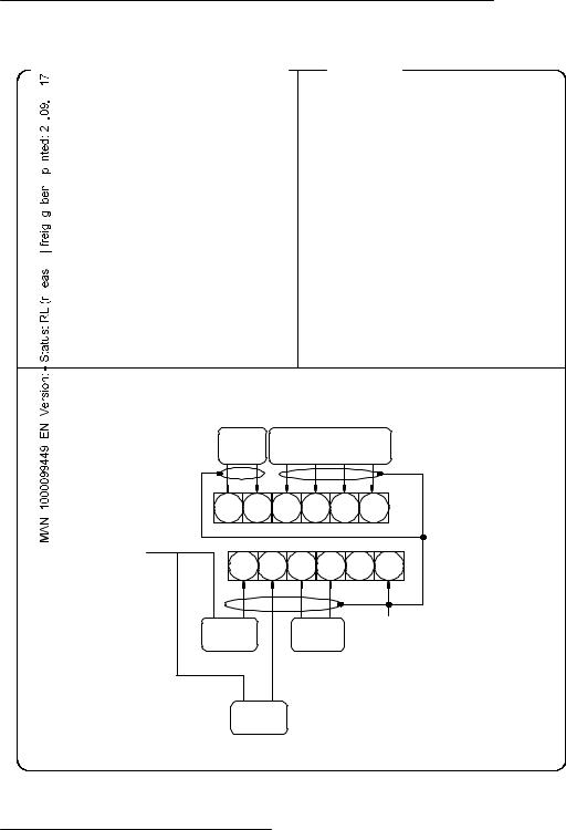
INPUT/OUTPUT
OPTIONAL MODULE (NO RELE MODULE)
q  ME200: 2 programmable on/off outputs
q  ME201: 1 programmable on/off output + 1 high frequency output
q  ME202: 1 0/4…20mA output + 2
  programmable on/off output
q  ME203: 1 RS232 port + 2 programmable
  on/off outputs
qME204: 1 RS232 port + 2 programmable
 on/off outputs + 1 0/4…20mA out
q  ME220: see the manual
LEGENDA
SC: Cable shield, electrically connected to ground and to the casing
CTS: Input terminal of the signal “CLEAR TO SEND” of the RS232 port
RD: Input terminal of the signal “RECEIVE DATA” RS232 port
TD: Output terminal of the signal “TRASMIT DATA” of the RS 232 port
SG: Terminal “SIGNAL GROUND” common to all signals of the RS232 port
C: Terminal connected with the COLLECTOR of the transistor of the on/off output
|
OUT 3 |
|
RS 232 |
|
|
E C CTS RD TD SG |
|||
|
21 22 23 24 25 26 |
|||
20 |
|
|
|
|
(M1) |
27 28 29 30 31 32 |
|||
|
||||
- |
+ |
E |
C |
SC |
INP2 |
OUT 4 |
|
||
|
- |
+ |
|
|
|
4..20mA |
|
|
|
9 |
|
210_EN_BU_4_3_5X.d |
|
||
|
|
oc |
SE 56
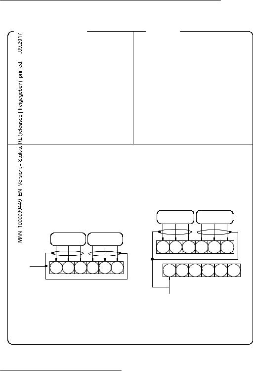
INPUT/OUTPUT
OPTIONAL RELE’ MODULE
ME205: 2 relay outputs with 1 NO contact + 1 NC contact each, 2A 60Vac, 60W/125Va
ME207: 2 relay outputs with 1 NO contact + 1 NC contact each, 2A 250Vac, 60W/125Va
LEGENDA
qSC: Cable shield, electrically connected to ground and to the casing
qC: relay – common
qNC: Normally closed contact
q NO: Normally open contact
OUT 3 |
OUT 4 |
NO NC C |
NO NC C |
14 |
21 22 23 24 25 26 |
(M1) |
OUT 4 |
OUT 3 |
C NC NO C |
NC NO |
26 25 24 23 22 21 |
32 31 30 29 28 27 |
SC |
10 |
|
210_EN_BU_4_3_5X.d |
|
||
|
|
oc |
 External power supply
10 K |
5 (+) |
3/40 Vdc (ON) |
0/1,5 Vdc (OFF) |
6 (-) |
SE 56
DIGITAL INPUT
 Internal power supply
+24 |
15 |
|
5 |
10 K |
|
|
6 |
0 |
20 |
The functions referring to the inputs could be divided in three groups:
 1) only assignable functions to the input 1 (page 12)
 2) Functions that act directly on the inputs independently from the select input (page 13)
 3) only assignable functions to the input 1 and only to the input 2 which they
  interact between them (some examples to page 14)
Remember that the activation of any functions of batch automatically disable the other. The list of such functions is suitable in the tab at page 36.
11 |
|
210_EN_BU_4_3_5X.d |
|
||
|
|
oc |
SE 56
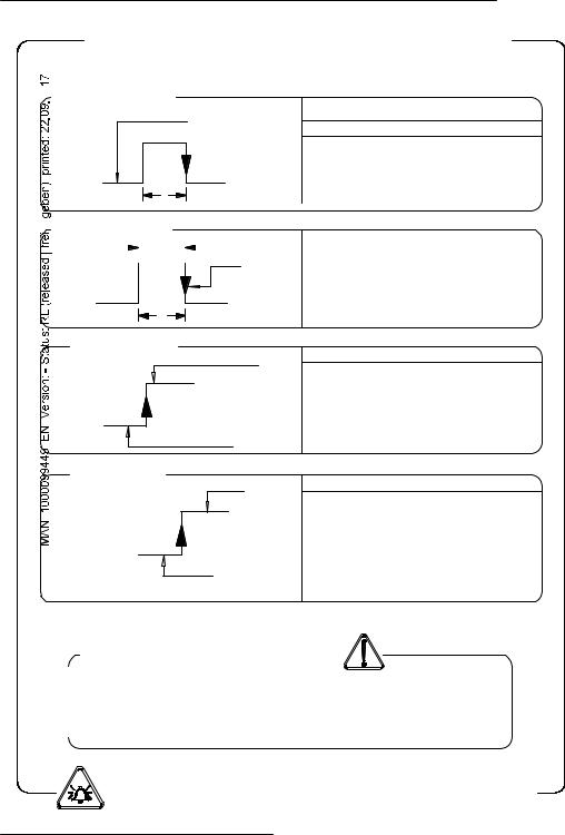
OPERATION ON INPUT ON/OFF
INPUT OPERATION STAGE (GENERIC FUNCTIONS)

 Auto-calibration
AUTOCALIB. OFF
3-40 V
0-1,5 V
T
Tmin<T<1sec. = autocalibration
T > 1 sec. = Auto zero
Necessary conditions for enabling the function
POS. 5.7 ENABLED
POS. 5.9 (batch on input 1) DISABLED
POS. 5.10 batch functions assign to input 2 (optional) DISABLED
 Reset totalizes
|
|
|
|
|
Necessary conditions for enabling the function |
|
|
BLOCK |
|
RESET |
|
3-40 V |
|
||||
|
|
||||
|
|||||
|
|
|
|
|
POS. 5.1 ÷ 5.4 ENABLED at least one |
N.B.: This function is even assignable to the input 2
0-1,5 V |
|
|
|
T |
Tmin = 100ms |
|
|
Block totalizes |
|
Necessary conditions for enabling the function |
|
Block totalizes |
|||
|
|||
3-40 V |
|
POS. 5.6 ENABLED |
|
|
|
||
|
|
POS. 12.5 (auto-batch) DISABLED |
|
0-1,5 V |
|
POS. 12.7 (batch consent) DISABLED |
|
|
|
||
Totalizers active |
|
||
Range change
Scale 2
3-40 V
0-1,5 V
Scale 1
Necessary conditions for enabling the function
POS. 5.8 ENABLE
POS. 5.9 (batch on input 1) DISABLED
POS. 5.10 batch functions assign to input 2 (optional) DISABLED
POS. 6.1-6.4 end-batch functions assign to output 2 1 e/o 2 DISABLED
|
|
Speed rate |
|
|
Tmin |
|
|
|
|
|
|
|
|
|
|
|
|
|
|
|
|
|
|
|
|
10 Hz |
220 ms |
|
|||
|
|
20 Hz |
110 ms |
|
|||
|
|
50 Hz |
45 ms |
|
|||
|
|
80 Hz |
30 ms |
|
|||
|
|
150 Hz |
15 ms |
|
|||
ATTENTION: time T must be ³ to Tmin
N.B.: THE FUNCTIONS ABOVE INDICATED ARE ENABLED ONLY ON INPUT 1
12 |
|
210_EN_BU_4_3_5X.d |
|
||
|
|
oc |
 Loading...