


6014
Type 6014
3/2-Way Solenoid Valve
3/2-Wege-Magnetventil
Électrovanne à 3/2 voies
Bedienungsanleitung
Manuel d‘utilisation
Operating Instructions
www.burkert.com
International address
www.burkert.com → Bürkert → Company → Locations
Manuals and data sheets on the Internet : www.burkert.com
Bedienungsanleitungen und Datenblätter im Internet: www.buerkert.de
Instructions de service et fiches techniques sur Internet: www.buerkert.fr
© 2012 Bürkert Werke GmbH
Operating Instr uctions 1308/18_EU-ML _00803455 / Original DE
Bürkert Fluid Control Systems
Sales Center
Christian-Bürkert-Str. 13-17
D-74653 Ingelfingen
Tel. + 49 (0) 7940 - 10 91 111
Fax + 49 (0) 7940 - 10 91 448
E-mail: info@de.buerkert.com
2
1. OPERATING INSTRUCTIONS
The operating instructions contain important information.
▶ Read the operating instructions carefully and follow the safety instruc-
tions in particular, and also observe the operating conditions.
▶ Operating instructions must be available to each user.
▶ The liability and warranty for the product / device are void if the oper-
ating instructions are not followed.
1.1. Symbols
▶ Designates an instruction to prevent risks.
→ designates a procedure which you must carry out.
Warning of injuries:
DANGER!
Imminent danger! Serious or fatal injuries.
WARNING!
Potential danger! Serious or fatal injuries.
CAUTION!
Danger! Minor or moderately severe injuries.
Warns of damage to property:
NOTE!
2. INTENDED USE
Incorrect use of the solenoid valve Type 6014 can be dangerous
to people, nearby equipment and the environment.
• The device is designed for blocking, dosing, filling and venting neutral
gaseous and liquid media.
• Do not use the device outdoors.
• Use according to the permitted data, operating conditions and
conditions of use specified in the contract documents and operating instructions. These are described in the chapter entitled “5.
Technical data”.
• The device may be used only in conjunction with third-party devices
and components recommended and authorised by Bürkert.
• Correct transportation, correct storage and installation and careful
use and maintenance are essential for reliable and problem-free
operation.
• Use the device only as intended.
2.1. Restrictions
If exporting the product / device, observe any existing restrictions.
english
3
2.4. Ex approval
The Ex approval is only valid if you use the modules and components
authorized by Bürkert as described in these operating instructions.
You may use the electronic modules only in combination with the pneumatic valve types released by Bürkert, otherwise the Ex approval will be
void!
If you make unauthorized changes to the system, the modules or components, the Ex approval will also be void.
2.2. Definition of term
In these operating instructions, the term “device” or “product” always
refers to the solenoid valve Type 6014.
2.3. Approvals
The approval mark indicated on the Bürkert type labels refers to the
Bürkert products.
e 1
03 5791
Devices which must bear the type approval mark were approved at the
Kraftfahrtbundesamt under the type approval number
e1*72/245*2006/96*5791*00
and are put into circulation with the indicated type approval mark. You
can obtain an extract of the type approval from the address below.
Bürkert Werke GmbH
Zulassungsbeauftragter,
Christian-Bürkert-Str. 13-17,
D-74653 Ingelfingen
english
4
3. BASIC SAFETY INSTRUCTIONS
These safety instructions do not make allowance for any contingencies
and events which may arise during installation, operation and maintenance.
Risk of injury from high pressure in the equipment/device.
▶ Before working on equipment or device, switch off the pressure and
deaerate/drain lines.
Risk of electric shock.
▶ Before working on equipment or device, switch off the power supply
and secure to prevent reactivation.
▶ Observe applicable accident prevention and safety regulations for
electrical equipment!
Risk of burns/Risk of fire if used continuously through hot
device surface.
▶ Keep the device away from highly flammable substances and media
and do not touch with bare hands.
General hazardous situations.
To prevent injury, ensure that:
▶ The system cannot be activated unintentionally.
▶ Installation and repair work may be carried out by authorized techni-
cians only.
▶ After an interruption in the power supply or pneumatic supply, ensure
that the process is restarted in a defined or controlled manner.
▶ The device may be operated only when in perfect condition and in
consideration of the operating instructions.
▶ The general rules of technology apply to application planning and
operation of the device.
To prevent damage to property of the device, ensure:
▶ Supply the media connections only with those media which are speci-
fied as flow media in the chapter entitled “5. Technical data” .
▶ Do not put any loads on the device (e.g. by placing objects on it or
standing on it).
▶ Do not make any modifications to the device. Do not paint the body
parts or screws.
3.1. Versions with explosion protection
DANGER!
Danger of explosion.
Improper use in the potentially explosive area may result in an explosion.
▶ Also follow the specifications in the certificate of conformity.
▶ If versions have ATEX approval, also follow the specifications in the
ATEX instructions.
english
Type 6014
5
4. PRODUCT DESCRIPTION
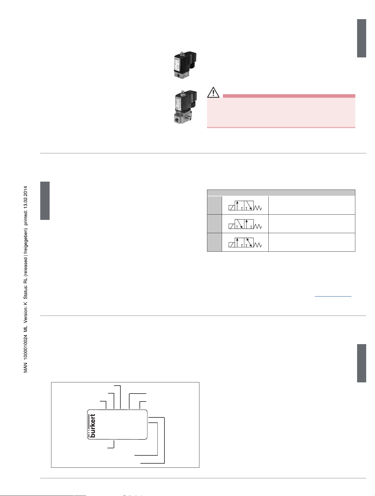
The direct-acting solenoid valve Type 6014 is available in two designs.
Type 6014 is used for the blocking, dosing, filling and
venting of neutral gaseous and liquid media, in particular for controlling single-acting pneumatic actuators
or technical vacuum. The modular designed valve can
be installed individually or in a block on the multiple
manifold.
Type 6014P is used as a special pilot valve for direct
installation on the externally controlled pneumatic actuators. It consists of the magnetic actuator Type 6014
and a special body with hollow screw which can be connected directly to the pilot air port of the actuator. The
valve features manual actuation as standard.
5. TECHNICAL DATA
5.1. Conformity
In accordance with the EC Declaration of conformity, the solenoid valve
Type 6014 is compliant with the EC Directives.
5.2. Standards
The applied standards, which verify conformity with the EC Directives,
can be found on the EC-Type Examination Certificate and / or the EC
Declaration of Conformity.
5.3. Operating conditions
WARNING!
Risk of injury from discharge of medium and pressure.
▶ If the device is used outdoors, do not expose it unprotected to the
weather conditions.
▶ Avoid heat sources which may cause the allowable temperature
range to be exceeded.
Ambient temperature -10 – +55 °C
Degree of protection IP65 in accordance with EN 60529 with
cable plug
english
6
5.4. Mechanical data
Dimensions See data sheet
Materials
Body Type 6014 brass, stainless steel 1.4305,
polyamide (PA, flange)
Type 6014P brass, polyamide (PA)
Hollow screw Type 6014P brass nickel-plated
aluminium anodized
Base plate Type 6014P aluminium anodized or IXEF
Sealing Type 6014 FKM, EPDM on request
Type 6014P FKM
Port connection Type 6014 G1/8, G1/4, flange
Type 6014P G1/8, G1/4
Hollow screw G1/8, G1/4
5.5. Fluidic data
Circuit functions
C
(NC)
2(A)
1(P)
3(R)
3/2-way valve, direct-acting,
normal output A unloaded
D
(NO)
2(B)
1(P)
3(R)
3/2-way valve, direct-acting, normal
output B pressurized
T
2(A)
1(P)
3(R)
3/2-way valve, direct-acting,
universal valve
Tab. 1: Circuit functions
Pressure range see type label
Media neutral gaseous and liquid media (e.g. compressed
air, town gas, natural gas, water, hydraulic fluid,
petrol, technical Vacuum), which do not attack body
and sealing materials
(see Chemical Resistance Chart www.burkert.com)
english
7
Medium temperature
FKM -10 – +100 °C (PA coil)
-10 – +120 °C (Epoxid coil)
Viscosity max. 21 mm²/s
5.6. Type label
Made in Germany
00450000
W14UN
CE
6014 C 1,5 FKM MS
G1/8 PN 0-16 bar
24V 50 Hz 8W
Identifications number
Voltage / frequency / power
Port connection / nominal pressure
Type
Circuit function
Orifice
Sealing material
Body material
Fig. 1: Type label (example)
5.7. Electrical data
Connection DIN EN 175301-803 (DIN 43 650), form A
for cable plug Type 2508
Operating voltage 24 V DC ± 10 % - max. residual ripple 10 %
24 V / 50 Hz
230 V / 50 Hz
Voltage tolerance ± 10 %
Nominal output 8 W
Impulse version 7 W
Nominal operating mode 100 % continuous operation
for block installation 5 W continuous operation on request
8 W intermittent operation 60 % (30 min)
english
Type 6014
8
6. INSTALLATION
6.1. Safety instructions
DANGER!
Risk of injury from high pressure in the equipment/device.
▶ Before working on equipment or device, switch off the pressure and
deaerate/drain lines.
Risk of electric shock.
▶ Before working on equipment or device, switch off the power supply
and secure to prevent reactivation.
▶ Observe applicable accident prevention and safety regulations for
electrical equipment.
Risk of injury from improper installation.
▶ Installation may be carried out by authorized technicians only and
with the appropriate tools!
▶ Secure system from unintentional activation.
▶ Following installation, ensure a controlled restart.
6.2. Fluid installation
DANGER!
Risk of injury from high pressure in the equipment/device.
▶ Before working on equipment or device, switch off the pressure and
deaerate/drain lines.
Installation position: any, coil preferably upwards.
Procedure:
→ Before installation, clean any possible dirt off the pipelines and flange
connections.
→ If required, install a dirt trap to prevent malfunctions.
Mesh size:
0,2 – 0,4 mm
Pay attention to the flow direction of the valve.
from 1(P) → 2(A) (Circuit function C) or
from 1(P) → 2(B) (Circuit function D)
english
9
Valve with threaded connection:
→ Use PTFE tape as sealing material.
NOTE!
Caution risk of breakage.
▶ Do not use the coil as a lifting arm.
→ Hold the device with a suitable tool (open-
end wrench) on the body and screw into
the pipeline.
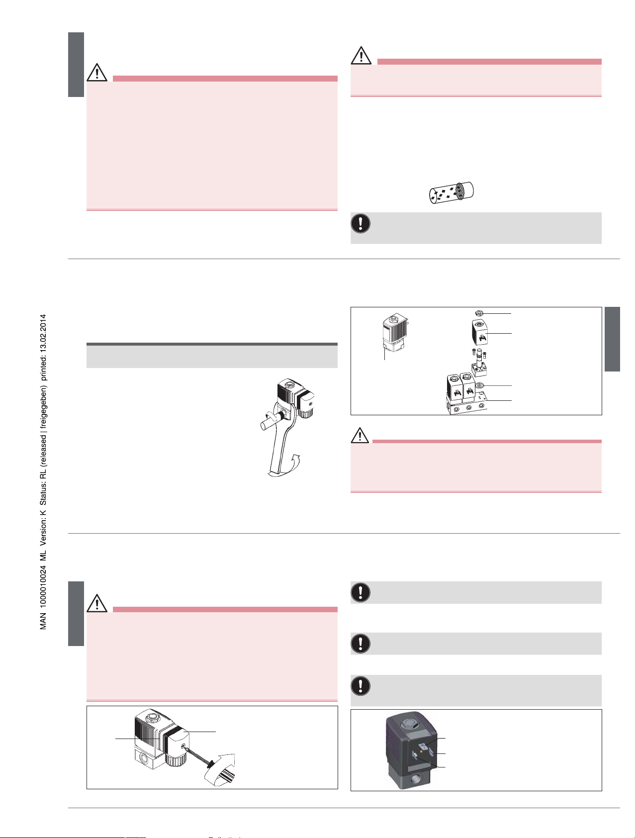
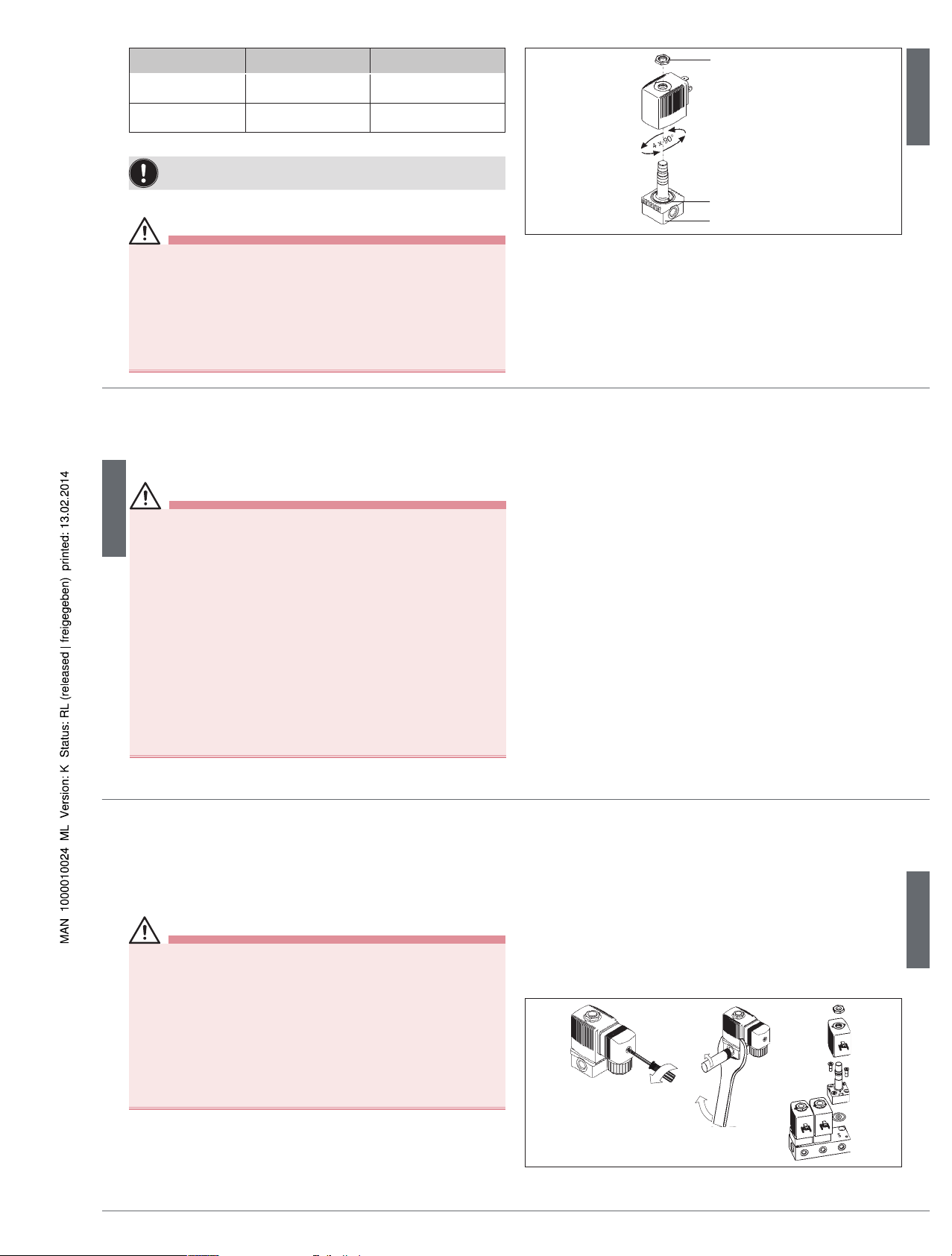
Valve with flanged connection:
→ Remove the cover plate.
→ Loosen the nut on the coil and remove coil.
Seal
Nut
Coil
Cover plate
Manifold
Fig. 2: Valve with flanged connection
WARNING!
Risk of injury due to escaping medium.
▶ Make certain the seals included with delivery are properly seated in
the valve.
▶ Ensure that the manifold is even.
▶ Ensure that the surface quality of the manifold is adequate.
→ Insert the seal into the body.
→ Screw the body onto the manifold (tightening torque: max. 1.5 Nm).
→ Attach the coil and screw on the nut (tightening torque: max. 5 Nm).
english
10
6.3. Electrical connection with cable plug
DANGER!
Risk of electric shock.
▶ Before working on equipment or device, switch off the power supply
and secure to prevent reactivation.
▶ Observe applicable accident prevention and safety regulations for
electrical equipment.
If the protective conductor contact between the coil and body is
missing, there is danger of electrical shock.
▶ Always connect protective conductor.
▶ Check electrical continuity between coil and body.
Seal
max. 1 Nm
Type 2508
Fig. 3: Electrical connection with cable plug
Note the voltage and current type as specified on the type label.
→ Check that seal is fitted correctly.
→ Connect and tighten the cable plug (tightening torque: max. 1 Nm).
The cable plug can be turned by 4 x 90°.
Control of pulse version
Correct polarity is essential to ensure that the device functions:
Note identification on the upper side of the coil.
Pulse duration at least 50 ms.
switch ON +
+
switch OFF
Terminal 1
Terminal 2
Protective conductor connection
Fig. 4: Pulse version
english
Type 6014
11
Polarity Specifications Terminal connections
- Switch ON +
Valve (P seat)
will be opened
(+) on terminal 2,
(–) on terminal 1
+ Switch OFF -
Valve (P seat)
will be closed
(+) on terminal 1,
(–) on terminal 2
Tab. 2: Control of pulse version
Use only cable plug without electrical wiring for pulse versions.
6.4. Rotation of coil
WARNING!
Risk of electric shock.
If the protective conductor contact between the coil and body is
missing, there is danger of electrical shock.
▶ Check protective conductor contact after installing the coil.
Overheating, risk of fire.
Connection of the coil without pre-assembled valve will result in
overheating and destroy the coil.
▶ Connect the coil with assembled fitting only.
Nut
max. 5 Nm
O-ring
Fitting
Fig. 5: Rotation of coil
The coil can be turned by 4 x 90° (for block installation only 2 x 180°).
→ Loosen nut.
→ Turn coil.
→ Tighten nut with suitable tool (open-end wrench, tightening torque:
max. 5 Nm).
english
12
7. MAINTENANCE, TROUBLESHOOTING
DANGER!
Risk of injury from high pressure in the equipment/device.
▶ Before working on equipment or device, switch off the pressure and
deaerate/drain lines.
Risk of electric shock.
▶ Before working on equipment or device, switch off the power supply
and secure to prevent reactivation.
▶ Observe applicable accident prevention and safety regulations for
electrical equipment.
Risk of burns/Risk of fire if used continuously through hot
device surface.
▶ Keep the device away from highly flammable substances and media
and do not touch with bare hands.
Risk of injury from improper maintenance.
▶ Maintenance may be carried out by authorized technicians only and
with the appropriate tools.
▶ Secure system from unintentional activation.
▶ Following maintenance, ensure a controlled restart.
7.1. Malfunctions
If malfunctions occur, check:
→ the line connectors,
→ the operating pressure,
→ the power supply and valve control.
If the valve still does not switch, please contact your Bürkert Service.
english
13
8. DISASSEMBLY
8.1. Safety instructions
DANGER!
Risk of injury from high pressure in the equipment/device.
▶ Before working on equipment or device, switch off the pressure and
deaerate/drain lines.
Risk of electric shock.
▶ Before working on equipment or device, switch off the power supply
and secure to prevent reactivation.
▶ Observe applicable accident prevention and safety regulations for
electrical equipment.
Risk of injury from improper disassembly.
▶ Disassembly may be carried out by authorized technicians only and
with the appropriate tools.
8.2. Disassembly
→ Turn off the pressure and vent the lines.
→ Switch off the power supply.
→ Loosen the cable plug.
Valve with threaded connection:
→ Hold the device with a suitable tool (Open-end wrench) on the
body and screw off the pipeline.
Valve with flanged connection:
→ Loosen the nut on the coil and remove coil.
→ Loosen the body from the manifold
Fig. 6: Disassembly
english
Type 6014
14
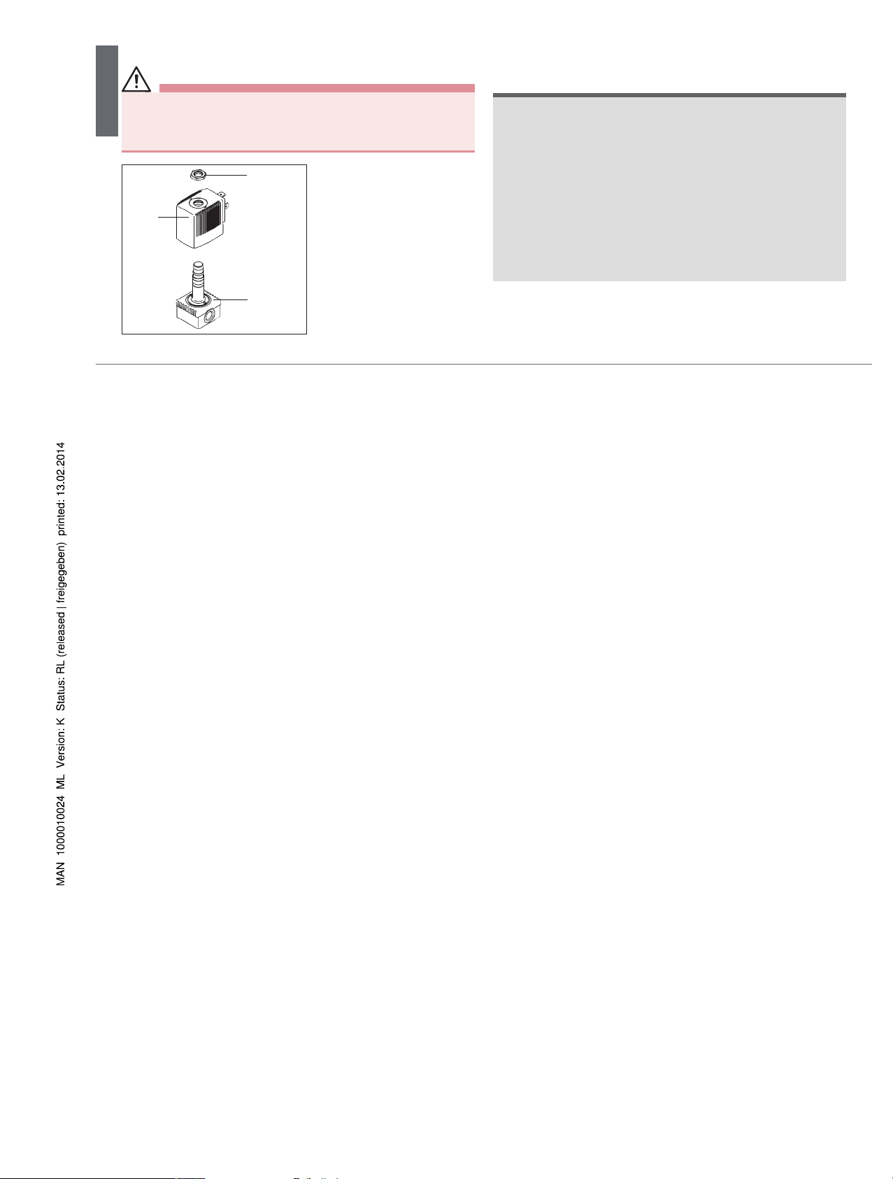
9. SPARE PARTS
CAUTION!
Risk of injury and/or damage by the use of incorrect parts!
Incorrect accessories and unsuitable spare parts may cause injuries
and damage the device and the surrounding area.
▶ Use only original accessories and original spare parts from Bürkert.
Fitting
Coil
Nut
Coil and fitting can be ordered
complete by quoting the identification number of the device.
(see type label)
Wearing part set on request.
Fig. 7: Spare parts
10. PACKAGING, TRANSPORT, STORAGE,
DISPOSAL
NOTE!
Transport damages.
Inadequately protected equipment may be damaged during transport.
▶ During transportation protect the device against wet and dirt in shock-
resistant packaging.
▶ Avoid exceeding or dropping below the allowable storage temperature.
Incorrect storage may damage the device.
▶ Store the device in a dry and dust-free location!
▶ Storage temperature: -40 - 80 °C.
Damage to the environment caused by device components contaminated with media.
▶ Observe applicable regulations on disposal and the environment.
english
Type 6014
 Loading...