


 Loading...
Type 8640
AirLINE
Modular valve terminal
Operating Instructions
Bedienungsanleitung Manuel d‘utilisation

We reserve the right to make technical changes without notice. Technische Änderungen vorbehalten.
Sous réserve de modifications techniques.
© Bürkert Werke GmbH, 2000–2014
Operating Instructions 1405/23_EU-en_00800665 / Original DE

Type 8640
|
|
Valve terminal type 8640 |
|
Table of Contents |
|
||
1. |
OPERATING INSTRUCTIONS........................................................................................................................................................ |
6 |
|
|
1.1. |
Symbols....................................................................................................................................................................................... |
6 |
2. |
AUTHORIZED USE.............................................................................................................................................................................. |
7 |
|
|
2.1. |
Restrictions................................................................................................................................................................................ |
7 |
3. |
BASIC SAFETY INSTRUCTIONS.................................................................................................................................................. |
8 |
|
4. |
GENERAL INFORMATION............................................................................................................................................................. |
10 |
|
|
4.1. |
Contact addresses.............................................................................................................................................................. |
10 |
|
4.2. |
Warranty.................................................................................................................................................................................... |
10 |
|
4.3. Information on the Internet............................................................................................................................................ |
10 |
|
5. |
PRODUCT DESCRIPTION............................................................................................................................................................. |
11 |
|
|
5.1. |
Application area................................................................................................................................................................... |
11 |
|
5.2. |
General description............................................................................................................................................................ |
11 |
|
5.3. Structure of the system................................................................................................................................................... |
12 |
|
6. |
TECHNICAL DATA............................................................................................................................................................................. |
13 |
|
|
6.1. |
Operating conditions......................................................................................................................................................... |
13 |
|
6.2. |
Conformity............................................................................................................................................................................... |
13 |
|
6.3. |
Standards................................................................................................................................................................................ |
13 |
|
6.4. |
General technical data...................................................................................................................................................... |
14 |
7. |
MODULES FOR CONVENTIONAL ELECTRICAL CONNECTION TECHNOLOGY............................................. |
15 |
|
8. |
FIELD BUS MODULE PROFIBUS DP/V1.............................................................................................................................. |
18 |
|
|
8.1. |
PROFIBUS DP/V1, IP20 - overview........................................................................................................................... |
18 |
|
8.2. |
PROFIBUS DP/V1, IP54 - overview........................................................................................................................... |
20 |
|
8.3. DIP switch (PROFIBUS address)................................................................................................................................ |
21 |
|
|
8.4. |
LED status display.............................................................................................................................................................. |
22 |
9. |
CONFIGURATION AND PARAMETER SETTINGS FOR PROFIBUS DP................................................................ |
24 |
|
|
9.1. Representation of the PROFIBUS-DP communication process................................................................ |
24 |
|
|
9.2. |
Start-Up.................................................................................................................................................................................... |
25 |
|
9.3. |
Mode inputs............................................................................................................................................................................ |
42 |
|
9.4. |
Input filter................................................................................................................................................................................ |
43 |
|
9.5. |
Special parameterization functions........................................................................................................................... |
43 |
|
9.6. |
Diagnosis................................................................................................................................................................................. |
44 |
|
9.7. |
Configuration and parameterization errors........................................................................................................... |
45 |
3
english

Type 8640
10. BUS MODULE RIO SLAVE (RIO/VA)...................................................................................................................................... |
46 |
|
|
10.1. Power supply (Power) RIO slave................................................................................................................................ |
47 |
|
10.2. Field bus connection RIO slave................................................................................................................................... |
47 |
|
10.3. LED Status Display............................................................................................................................................................. |
48 |
|
10.4. DIP switch settings............................................................................................................................................................. |
49 |
11. |
FELDBUS MODULE DEVICENET.............................................................................................................................................. |
52 |
|
11.1. DeviceNet, IP20 - overview............................................................................................................................................ |
52 |
|
11.2. DeviceNet, IP54 - overview............................................................................................................................................ |
54 |
|
11.3. Position of the DIP switches......................................................................................................................................... |
55 |
|
11.4. LED status display.............................................................................................................................................................. |
56 |
|
11.5. Applications object............................................................................................................................................................. |
58 |
12. CONFIGURATION AND PARAMETER SETTINGS FOR DEVICENET...................................................................... |
59 |
|
|
12.1. Configuration of process data...................................................................................................................................... |
59 |
|
12.2. Configuration of the safety position of solenoid valves if bus error....................................................... |
59 |
|
12.3. Mode inputs............................................................................................................................................................................ |
60 |
|
12.4. Input filter................................................................................................................................................................................ |
61 |
13. |
FELDBUS MODULE CANOPEN................................................................................................................................................. |
62 |
|
13.1. CANopen, IP20 - overview.............................................................................................................................................. |
62 |
|
13.2. CANopen, IP54 - overview.............................................................................................................................................. |
63 |
|
13.3. Position of the DIP switches......................................................................................................................................... |
65 |
|
13.4. LED status display.............................................................................................................................................................. |
66 |
14. CONFIGURATION AND PARAMETER SETTINGS FOR CANOPEN......................................................................... |
68 |
|
|
14.1. Description of the CANopen field bus node......................................................................................................... |
68 |
|
14.2. Object overview.................................................................................................................................................................... |
68 |
|
14.3. Detailed description of the supported objects.................................................................................................... |
69 |
|
14.4. Input filter................................................................................................................................................................................ |
72 |
|
14.5. Mode inputs............................................................................................................................................................................ |
72 |
|
14.6. Outputs..................................................................................................................................................................................... |
74 |
|
14.7. Example for start-up.......................................................................................................................................................... |
75 |
15. FIELD BUS MODULES PROFINET IO, ETHERNET/IP AND MODBUS TCP....................................................... |
77 |
|
|
15.1. PROFINET IO, EtherNet/IP and MODBUS TCP, IP20 - overview............................................................... |
77 |
|
15.2. LED status display.............................................................................................................................................................. |
79 |
|
15.3. Mode inputs............................................................................................................................................................................ |
81 |
|
15.4. Input filter................................................................................................................................................................................ |
82 |
|
15.5. Fault Action and Fault Value......................................................................................................................................... |
83 |
|
15.6. Web server.............................................................................................................................................................................. |
83 |
16. CONFIGURATION AND PARAMETER SETTINGS FOR PROFINET IO.................................................................. |
86 |
|
|
16.1. Hardware configuration by GSDML based on the example of Siemens STEP 7............................. |
86 |
4 |
16.2. Parameter settings for the PROFINET IO slave.................................................................................................. |
89 |
english

Type 8640
17. |
CONFIGURATION AND PARAMETER SETTINGS FOR ETHERNET/IP................................................................. |
91 |
|
17.1. Addressing.............................................................................................................................................................................. |
91 |
|
17.2. EDS file..................................................................................................................................................................................... |
91 |
|
17.3. Object model......................................................................................................................................................................... |
91 |
|
17.4. Configuration of process data...................................................................................................................................... |
93 |
|
17.5. Applications object............................................................................................................................................................. |
94 |
18. |
CONFIGURATION AND PARAMETER SETTINGS FOR MODBUS TCP................................................................. |
95 |
|
18.1. Modbus application protocol........................................................................................................................................ |
95 |
|
18.2. Modbus data model........................................................................................................................................................... |
96 |
|
18.3. Mapping to TCP/IP............................................................................................................................................................. |
96 |
|
18.4. Connection-oriented structure..................................................................................................................................... |
96 |
|
18.5. 8640 objects........................................................................................................................................................................... |
97 |
19. |
ELECTRICAL BASE MODULE OUTPUT................................................................................................................................. |
99 |
|
19.1. Collective socket................................................................................................................................................................. |
99 |
|
19.2. Valve outputs...................................................................................................................................................................... |
100 |
|
19.3. Valve outputs with manual / automatic switching......................................................................................... |
101 |
|
19.4. Valve outputs with external switch-off................................................................................................................. |
103 |
20. |
ELECTRICAL BASE MODULE INPUT................................................................................................................................... |
104 |
|
20.1. Terminal inputs for repeaters (initiators)............................................................................................................. |
104 |
|
20.2. Plug inputs (M8 circular plugs) for repeaters (initiators)........................................................................... |
105 |
21. |
PNEUMATIC BASE MODULE................................................................................................................................................... |
106 |
|
21.1. General description......................................................................................................................................................... |
106 |
|
21.2. Pneumatic base module with integrated P shut-off...................................................................................... |
107 |
22. |
VALVES................................................................................................................................................................................................ |
109 |
|
22.1. General description......................................................................................................................................................... |
109 |
23. |
INSTALLATION OF AIRLINE QUICK..................................................................................................................................... |
112 |
|
23.1. Safety instructions........................................................................................................................................................... |
112 |
|
23.2. Installation on standard rail........................................................................................................................................ |
113 |
|
23.3. Installation of AirLINE Quick...................................................................................................................................... |
113 |
|
23.4. Dimensions of the flange images for AirLINE Quick.................................................................................... |
115 |
24. |
PACKAGING, TRANSPORT....................................................................................................................................................... |
117 |
25. |
STORAGE........................................................................................................................................................................................... |
117 |
26. |
DISPOSAL.......................................................................................................................................................................................... |
117 |
5
english

Type 8640
Operating instructions
1.OPERATING INSTRUCTIONS
The operating instructions describe the entire life cycle of the device. Keep these instructions in a location which is easily accessible to every user, and make these instructions available to every new owner of the device.
 WARNING!
The operating instructions contain important safety information!
Failure to observe these instructions may result in hazardous situations.
• The operating instructions must be read and understood.
1.1.Symbols
 DANGER!
Warns of an immediate danger!
• Failure to observe the warning will result in a fatal or serious injury.
 WARNING!
Warns of a potentially dangerous situation!
• Failure to observe the warning may result in serious injuries or death.
 CAUTION!
Warns of a possible danger!
• Failure to observe this warning may result in a moderate or minor injury.
NOTE!
Warns of damage to property!
• Failure to observe the warning may result in damage to the device or the equipment.
 Indicates important additional information, tips and recommendations.
 Refers to information in these operating instructions or in other documentation.
→→designates a procedure which you must carry out.
6
english
Type 8640
Authorized use
2.AUTHORIZED USE
Use of the valve terminal type 8640 for purposes other than those for which it is intended may represent a hazard to persons, nearby equipment and the environment.
•Do not use the device outdoors unprotected.
•Use according to the authorized data, service and operating conditions specified in the contract documents and operating instructions. These are described in the chapter on “Technical data”.
•The device may be used only in conjunction with third-party devices and components recommended and authorized by Bürkert.
•Correct transportation, storage, and installation, as well as careful use and maintenance are essential for reliable and faultless operation.
•Use the device only as intended.
The pneumatic modular valve terminal type 8640 was developed in compliance with accepted safety regulations and is state-of-the-art. Nevertheless, dangerous situations may occur.
2.1.Restrictions
If exporting the system/device, observe any existing restrictions.
7
english

Type 8640
Basic safety instructions
3.BASIC SAFETY INSTRUCTIONS
These safety instructions do not make allowance for any:
•Contingencies and events which may arise during the installation, operation and maintenance of the devices.
•Local safety regulations – the operator is responsible for observing these regulations, also with reference to the installation personnel.
Danger – high pressure!
• Before dismounting pneumatic lines and valves, turn off the pressure and vent the lines.
Risk of electric shock!
• Before reaching into the device or the equipment, switch off the power supply and secure to prevent reactivation!
• Observe applicable accident prevention and safety regulations for electrical equipment!
Risk of burns/risk of fire if used continuously through hot device surface!
• Keep the device away from highly flammable substances and media and do not touch with bare hands.
General Hazardous Situations.
To prevent injuries:
• Do not supply the medium connectors of the system with aggressive or flammable media.
• Do not physically stress the body (e.g. by placing objects on it or standing on it).
• Note that pipes and valves must not become detached in systems which are under pressure.
• Before any work is done on the system, always switch off the power supply.
• Design the pressure supply with the largest possible volume to prevent a pressure drop when the system is switched on.
• Ensure that the system cannot be activated unintentionally.
• Installation and maintenance work may be carried out only by authorized technicians with the appropriate tools.
• After an interruption in the power supply or pneumatic supply, ensure that the process is restarted in a defined or controlled manner.
• The device may be operated only when in perfect condition and in consideration of the operating instructions.
• The general rules of technology must be observed for application planning and operation of the device.
8
english

Type 8640
Basic safety instructions
NOTE!
Prevent a pressure drop!
To prevent a pressure drop, design the system pressure supply with the largest possible volume.
Electrostatic sensitive components/modules!
The device contains electronic components, which react sensitively to electrostatic discharge (ESD). Contact with electrostatically charged persons or objects is hazardous to these components. In the worst case scenario, they will be destroyed immediately or will fail after start-up.
•Observe the requirements in accordance with EN 61340-5-1 and 5-2 to minimize/avoid the possibility of damage caused by a sudden electrostatic discharge!
•Also, ensure that you do not touch electronic components when the power supply voltage is present!
9
english

Type 8640
General information
4.GENERAL INFORMATION
4.1.Contact addresses
Germany
Bürkert Fluid Control Systems
Sales Center
Christian-Bürkert-Str. 13-17
D-74653 Ingelfingen
Tel. + 49 (0) 7940 - 10 91 111
Fax + 49 (0) 7940 - 10 91 448
E-mail: info@de.buerkert.com
International
Contact addresses can be found on the final pages of the printed operating instructions.
And also on the Internet at:
www.burkert.com
4.2. Warranty
The warranty is only valid if the device is used as intended in accordance with the specified application conditions.
4.3. Information on the Internet
The operating instructions and data sheets for Type 8640 can be found on the Internet at:
www.buerkert.com
10
english
Type 8640
Product description
5.PRODUCT DESCRIPTION
5.1.Application area
The valve terminal type 8640 is intended for use in an industrial environment. The valves can be combined very easily and efficiently thanks to the modular design.
 DANGER!
Risk of electric shock!
•Before reaching into the device or the equipment, switch off the power supply and secure to prevent reactivation.
•Observe applicable accident prevention and safety regulations for electrical equipment.
5.2.General description
Thanks to its strictly modular construction in terms of the pneumatic and electrical interfaces the type 8640 valve terminal is suitable for a wide range of tasks, including complex ones. By aligning pneumatic modules in sequence with varying numbers of valves it is possible to configure up to 24 valve functions on one valve terminal.
The electrical connection technology can be implemented as required via field bus interfaces, collective sockets (parallel connection technology) or multi-pole interfaces. The valves are designed for various usage scenarios. The body and connection modules are manufactured using high quality plastic (polyamide) and can be connected and released easily thanks to an integrated attachment mechanism.
Figure 1: Example of usage for pneumatic modular valve terminal type 8640
11
english

Type 8640
Product description
5.3.Structure of the system
Each valve terminal is configured according to customer requirements. To ensure optimal performance for the task in question a large range of electrical and fluid-related components is available.
Electric cable termination module
Terminal module for feedback indicator
|
|
|
|
|
|
|
Extension module for electrical inputs |
||||||||
|
|
|
|
|
|
|
|||||||||
Electric cable |
|
|
|
|
|
|
|
|
|
|
|
Multipole feedback indicator inputs (initiators) |
|||
|
|
|
|||||||||||||
|
|
|
|
|
|
|
|
|
|
|
|||||
|
|
|
|
|
|
|
|
|
|
|
|
|
|
||
termination module |
|
|
|
|
|
|
|
|
|
|
|
||||
|
|
|
|
Electric base module |
|||||||||||
|
|
|
|
||||||||||||
|
|
|
|
|
|
|
|
|
Field bus module |
||||||
|
|
|
|
|
|
|
|
||||||||
Pneumatic connection |
|
|
|
|
|
|
|
|
Multipole valve outputs |
||||||
|
|
|
|
|
|
|
|
||||||||
|
|
|
|
|
|
|
|
||||||||
|
|
|
|
|
|
|
|
|
|
Multiple connection module |
|||||
module |
|
|
|
|
|
|
|
|
|
|
|
|
|
||
|
|
|
|
|
|
|
|
|
|
|
|
|
|||
|
|
|
|
|
|
|
|
|
|
|
|
|
|
||
|
|
|
|
|
|
|
|
|
|||||||
|
|
|
|
Pneumatic base module |
|||||||||||
|
|
|
|
||||||||||||
|
|
|
|
|
|
|
|
|
Pneumatic |
||||||
|
|
|
|
|
|
|
|
|
|||||||
|
|
|
|
|
|
|
|
|
|||||||
|
|
|
|
|
|
|
|
|
connection module |
||||||
Valves of type 6525 (5/2-way)
Figure 2: Example for the configuration of the modular electric valve terminal type 8640
12
english
Type 8640
Technical data
6.TECHNICAL DATA
6.1.Operating conditions
Ambient temperature: |
0 ... +50 °C |
Storage temperature: |
-20 ... +60 °C |
Nominal operating mode: |
Long-term operation (100% ED) |
Operating voltage: |
24 V / DC ± 10 %, residual ripple for field bus interface 1 Vss |
Protection class: |
3 in accordance with VDE 0580 |
Power consumption: |
Power consumption is dependent on the type of electrical connection technology. |
1.For the collective socket (parallel connection technology), and multi-pole interfaces power consumption is determined by the valve type used, but limited to a total current of 3 A maximum. For a multi-pole solution combined with repeaters there is a further summed current, also limited to a maximum of 3 a.
2.For the field bus interface the total current can be determined according to the equation:
l total = I base + (n x I valve) + (m x l repeater)
I base
n m
I valve
l repeater
NOTE!
base current dep. on field bus system
PROFIBUS-DP V1 |
200 mA |
DeviceNet |
200 mA |
CANopen |
200 mA |
number of valves number of repeaters
nominal current of valve type
power consumption of repeater (m x I repeater) = max. 650 mA
Always use safety low voltage according to protection class 3 VDE 0580!
6.2.Conformity
Type 8640 conforms with the EC Directives according to the EC Declaration of Conformity.
6.3.Standards
The applied standards, which verify conformity with the EC Directives, can be found on the EC-Type Examination Certificate and / or the EC Declaration of Conformity.
13
english

Type 8640
Modules for conventional electrical connection technology
6.4.General technical data
6.4.1.Add-on dimension 11 mm
Add-on dimension |
|
|
|
|
|
|
11 mm |
|
|
|
||
|
|
|
|
|
|
|
|
|
|
|
|
|
Operating principle |
|
C/D (3/2-way) |
|
|
|
2xC (2x3/2-way) |
|
|
LN (5/3-way) |
|||
Valve |
|
|
Type 6524 |
|
|
|
Type 6524 |
|
|
Type 0460 |
||
|
|
|
|
|
|
|
|
|
|
|
|
|
Operating principle |
|
H (5/2-way) |
|
|
|
|
|
|
|
H (5/2-impulse) |
||
Valve |
|
|
Type 6525 |
|
|
|
|
|
|
|
Type 0460 |
|
|
|
|
|
|
|
|
|
|
|
|
|
|
Flow rate [l/min] |
300 |
|
|
|
300 |
|
200 |
|||||
|
|
|
|
|
|
|
|
|
|
|
|
|
Pressure range [bar] |
2.5 ... 7 |
|
|
|
2.5 ... 7 |
|
2.5 ... 7 |
|||||
|
|
2,5 ... 10 |
|
|
|
2,5 ... 10 |
|
|
|
|||
|
|
|
|
|
|
|
|
|
|
|
|
|
Power rating [W] |
1 |
|
|
|
|
2 x 0.25 |
|
|
2 x 0.9 |
|||
|
|
|
|
|
|
|
|
|
|
|
|
|
Current before/after power |
43/28 |
|
|
|
2 x 43/18 |
|
|
2 x 41/- |
||||
reduction [mA] |
|
|
|
|
|
|
|
|
|
|
|
|
|
|
|
|
|
|
|
|
|
|
|
|
|
Valve locations |
|
max. 24 |
|
|
|
max. 12 |
|
|
max. 12 |
|||
Repeater |
|
|
max. 32 |
|
|
|
max. 32 |
|
|
max. 32 |
||
|
|
|
|
|
|
|
|
|
|
|||
Electrical modules |
|
6-fold*, 8-fold, 12-fold |
|
6-fold*, 8-fold, 12-fold |
|
|
6-fold*, 8-fold, 12-fold |
|||||
|
|
|
|
|
|
|
|
|
|
|
|
|
Pneumatic modules |
|
2-fold, 8-fold |
|
|
|
2-fold, 8-fold |
|
|
2-fold, 8-fold |
|||
|
|
|
|
|
|
|
|
|
|
|
|
|
Protection class in terminal |
|
IP40 |
|
|
|
IP40 |
|
|
IP40 |
|||
design |
|
|
IP20 |
|
|
|
IP20 |
|
|
IP20 |
||
|
|
|
|
|
|
|
|
|
|
|
|
|
* Configuration with 6-fold modules on request |
|
|
|
|
|
|
|
|
||||
6.4.2. |
Add-on dimension 16.5 mm and 19 mm |
|
|
|
||||||||
|
|
|
|
|
|
|
|
|
|
|
||
Add-on dimension |
|
|
16,5 mm |
|
|
|
|
|
|
19 mm |
||
|
|
|
|
|
|
|
|
|||||
Operating principle |
|
C/D (3/2-way) |
|
|
C/D (3/2-way) |
|||||||
Valve |
|
|
Type 6526 |
|
|
|
|
|
Type 5470 |
|||
|
|
|
|
|
|
|
|
|
|
|||
Operating principle |
|
H (5/2-way) |
|
|
|
|
G (4/2-way) |
|||||
Valve |
|
|
Type 6527 |
|
|
|
|
|
Type 5470 |
|||
|
|
|
|
|
|
|
|
|
|
|
||
Flow rate [l/min] |
|
700 |
|
|
|
|
|
300 |
||||
|
|
|
|
|
|
|
|
|
|
|
||
Pressure range [bar] |
|
2 ... 10 |
|
|
|
|
|
2 ... 8 |
||||
|
|
|
|
|
|
|
|
|
|
|||
Power rating [W] |
|
1 |
|
|
2 |
|
1 |
|
2 |
|||
|
|
|
|
|
|
|
|
|
||||
Current before/after power |
|
42/33 |
|
85/52 |
|
42/- |
|
|
84/- |
|||
reduction [mA] |
|
|
|
|
|
|
|
|
|
|
|
|
|
|
|
|
|
|
|
|
|
|
|
|
|
Valve locations |
|
|
max. 24 |
|
|
|
|
|
|
|
max. 24 |
|
|
|
|
|
|
|
|
|
|
|
|
|
|
Repeater |
|
|
|
max. 32 |
|
|
|
|
|
|
|
max. 32 |
|
|
|
|
|
||||||||
Electrical modules |
|
4-fold, 6-fold, 8-fold |
|
2-fold, 5-fold, 6-fold |
||||||||
|
|
|
|
|
|
|
|
|||||
Pneumatic modules |
|
2-fold, 4-fold |
|
|
|
|
2-fold, 3-fold |
|||||
Protection class in terminal |
|
|
IP54 |
|
|
|
|
|
|
|
IP54 |
|
design |
|
|
|
IP20 |
|
|
|
|
|
|
|
IP20 |
|
|
|
|
|
|
|
|
|
|
|
|
|
14
english
Type 8640
Modules for conventional electrical connection technology
7.MODULES FOR CONVENTIONAL ELECTRICAL CONNECTION TECHNOLOGY
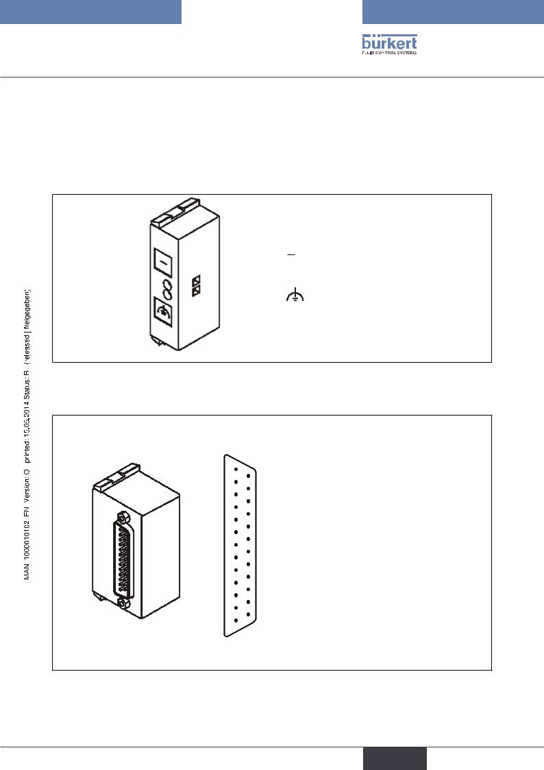
7.4.1.Collective socket module
The collective socket module serves as a central connecting element for ground and functional earth.
Allocation plan
Ground
Functional earth
Figure 3: Collective socket module for valve outputs
7.4.2. Multi-pole connection for valve outputs
|
|
Pin 1 |
Valve 1 |
|
|
|
Pin 2 |
Valve 2 |
|
|
|
Pin 3 |
Valve 3 |
|
|
|
Pin 4 |
Valve 4 |
|
13 |
|
Pin 5 |
Valve 5 |
|
25 |
Pin 6 |
Valve 6 |
||
12 |
Pin 7 |
Valve 7 |
||
11 |
24 |
Pin 8 |
Valve 8 |
|
|
||||
23 |
Pin 9 |
Valve 9 |
||
10 |
||||
22 |
Pin 10 |
Valve 10 |
||
|
||||
9 |
Pin 11 |
Valve 11 |
||
8 |
21 |
Pin 12 |
Valve 12 |
|
7 |
20 |
Pin 13 |
Valve 13 |
|
19 |
Pin 14 |
Valve 14 |
||
6 |
||||
|
18 |
Pin 15 |
Valve 15 |
|
5 |
Pin 16 |
Valve 16 |
||
4 |
17 |
Pin 17 |
Valve 17 |
|
3 |
16 |
Pin 18 |
Valve 18 |
|
15 |
Pin 19 |
Valve 19 |
||
2 |
||||
14 |
Pin 20 |
Valve 20 |
||
1 |
Pin 21 |
Valve 21 |
||
|
|
Pin 22 |
Valve 22 |
|
|
|
Pin 23 |
Valve 23 |
|
|
|
Pin 24 |
Valve 24* |
|
|
|
Pin 25 |
Ground |
Figure 4: Multi-pole module for valve outputs D-SUB IP54 and allocation of the D-SUB plug
* Multi-pole for manual automation only 23 bit, as Pin 24 used for permanent 24 V.
15
english
Type 8640
Modules for conventional electrical connection technology
Accessories
D-SUB plug |
25-pin |
IP54 5 m cable |
Id.-No. 917 494 |
D-SUB plug |
25-pin |
IP54 10 m cable |
Id.-No. 917 495 |
|
|
|
|
Colour code for D-SUB cable
The wires are soldered 1:1 to the D_SUB plug, i.e. wire 1 ws to Pin 1 D-SUB etc.
Pin/Wire |
Wire colour |
Code |
|
|
|
1 |
white |
ws |
|
|
|
2 |
brown |
br |
|
|
|
3 |
green |
gn |
|
|
|
4 |
yellow |
ge |
|
|
|
5 |
grey |
gr |
|
|
|
6 |
pink |
rs |
|
|
|
7 |
blue |
bl |
|
|
|
8 |
red |
rt |
|
|
|
9 |
black |
sw |
|
|
|
10 |
violet |
vi |
|
|
|
11 |
grey-pink |
grrs |
|
|
|
12 |
red-blue |
rtbl |
|
|
|
13 |
white-green |
wsgn |
|
|
|
Pin/Wire |
Wire colour |
Code |
|
|
|
14 |
brown-green |
brgn |
|
|
|
15 |
white-yellow |
wsge |
|
|
|
16 |
yellow-brown |
gebr |
|
|
|
17 |
white-grey |
wsgr |
|
|
|
18 |
grey-brown |
grbr |
|
|
|
19 |
white-pink |
wsrs |
|
|
|
20 |
pink-brown |
rsbr |
|
|
|
21 |
white-blue |
wsbl |
|
|
|
22 |
brown-blue |
brbl |
|
|
|
23 |
white-red |
wsrt |
|
|
|
24 |
brown-red |
brrt |
|
|
|
25 |
white-black |
wssw |
|
|
|
|
|
|
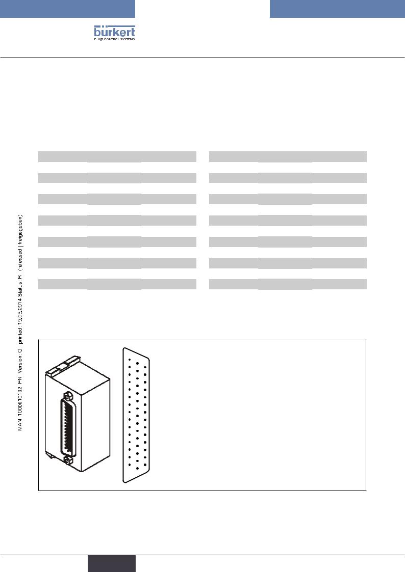
7.4.3.Multi-pole connection with repeater inputs (initiators)
15
14 30 44
13 29 43
12 28 42
11 27 41
10 26 40
9 25 39
8 24 38
7 23 37
6 22 36
5 21 35
4 20 34
3 19 33
2 18 32
1 1716 31
Pin 1 |
Input 1 |
Pin 20 |
Input 20 |
Pin 2 |
Input 2 |
Pin 21 |
Input 21 |
Pin 3 |
Input 3 |
Pin 22 |
Input 22 |
Pin 4 |
Input 4 |
Pin 23 |
Input 23 |
Pin 5 |
Input 5 |
Pin 24 |
Input 24 |
Pin 6 |
Input 6 |
Pin 25 |
Input 25 |
Pin 7 |
Input 7 |
Pin 26 |
Input 26 |
Pin 8 |
Input 8 |
Pin 27 |
Input 27 |
Pin 9 |
Input 9 |
Pin 28 |
Input 28 |
Pin 10 |
Input 10 |
Pin 29 |
Input 29 |
Pin 11 |
Input 11 |
Pin 30 |
Input 30 |
Pin 12 |
Input 12 |
Pin 31 |
Input 31 |
Pin 13 |
Input 13 |
Pin 32 |
Input 32 |
Pin 14 |
Input 14 |
... |
|
Pin 15 |
Input 15 |
Pin 43 |
24 V |
Pin 16 |
Input 16 |
Pin 44 |
Ground |
Pin 17 |
Input 17 |
|
|
Pin 18 |
Input 18 |
|
|
Pin 19 |
Input 19 |
|
|
Figure 5: Multi-pole module for repeater inputs D-SUB IP54 and allocation of the D-SUB plug
16
english

Type 8640
Modules for conventional electrical connection technology
Accessories
D-SUB plug |
44-pin |
IP54 5 m cable |
Id.-No. 917 496 |
D-SUB plug |
44-pin |
IP54 10 m cable |
Id.-No. 917 497 |
|
|
|
|
Colour code for D-SUB cable
The wires are soldered 1:1 to the D_SUB plug, i.e. wire 1 ws to Pin 1 D-SUB etc.
Pin/Wire |
Wire colour |
Code |
|
|
|
1 |
white |
ws |
|
|
|
2 |
brown |
br |
|
|
|
3 |
green |
gn |
|
|
|
4 |
yellow |
ge |
|
|
|
5 |
grey |
gr |
|
|
|
6 |
pink |
rs |
|
|
|
7 |
blue |
bl |
|
|
|
8 |
red |
rt |
|
|
|
9 |
black |
sw |
|
|
|
10 |
violet |
vi |
|
|
|
11 |
grey-pink |
grrs |
|
|
|
12 |
red-blue |
rtbl |
|
|
|
13 |
white-green |
wsgn |
|
|
|
14 |
brown-green |
brgn |
|
|
|
15 |
white-yellow |
wsge |
|
|
|
16 |
yellow-brown |
gebr |
|
|
|
17 |
white-grey |
wsgr |
18 |
grey-brown |
grbr |
|
|
|
19 |
white-pink |
wsrs |
|
|
|
20 |
pink-brown |
rsbr |
|
|
|
21 |
white-blue |
wsbl |
|
|
|
22 |
brown-blue |
brbl |
|
|
|
Pin/Wire |
Wire colour |
Code |
|
|
|
23 |
white-red |
wsrt |
|
|
|
24 |
brown-red |
brrt |
|
|
|
25 |
white-black |
wssw |
|
|
|
26 |
brown-black |
brsw |
|
|
|
27 |
grey-green |
grgn |
|
|
|
28 |
yellow-grey |
grgr |
|
|
|
29 |
pink-green |
rsgn |
|
|
|
30 |
yellow-pink |
gers |
|
|
|
31 |
green-blue |
gnbl |
|
|
|
32 |
yellow-blue |
gebl |
|
|
|
33 |
green-red |
gnrt |
|
|
|
34 |
yellow-red |
gert |
|
|
|
35 |
green-black |
gnsw |
|
|
|
36 |
yellow-black |
gesw |
|
|
|
37 |
grey-blue |
grbl |
|
|
|
38 |
pink-blue |
rsbl |
|
|
|
39 |
grey-red |
grrt |
40 |
pink-red |
rsrt |
|
|
|
41 |
grey-black |
grsw |
|
|
|
42 |
pink-black |
rssw |
|
|
|
43 |
blue-black |
blsw |
|
|
|
44 |
red-black |
rtsw |
|
|
|
17
english

Type 8640
Field bus module PROFIBUS DP/V1
8.FIELD BUS MODULE PROFIBUS DP/V1
8.1.PROFIBUS DP/V1, IP20 - overview
LED Status Display |
|
|
|
|
|
|
|
Power Supply |
|
|
|
|
|
|
|||
|
|
|
|
Functional earth |
||||
|
|
|
||||||
DIP Switches |
|
|
|
|
|
|
||
|
|
|
|
|
|
|||
|
|
|
|
|
|
|||
|
|
|
|
|
Field bus connection |
|||
|
|
|
|
|||||
|
|
|
|
|
|
|
|
|
Connection for RIO |
|
|
||||||
|
|
|
||||||
slave bus module – see “10. Bus Module Rio Slave (RIO/VA)”, page 46
Figure 6: Overview of field bus module PROFIBUS DP IP20
 The DIP switches can be operated through the covering film.
8.1.1. Power supply IP20
The 4-pole plug-in connector for the power supply is configured as follows:
24 V DC (2) |
|
|
|
|
|
|
|
|
|
|
|
|
|
|
|
|
|
valves / |
|
|
|
|
|
|
|
|
|
Pin 1 |
|
|
|
|
|
Pin 4 |
|
outputs |
|
|
|
|
|
|
|
|
|
|
|
|
|
|
|
|
|
|
|
|
|
|
|
|
|
|
|
|
|
|
|
|
|
||
24 V DC (4) |
|
|
|
|
|
|
|
|
|
|
|
|
|
|
|
|
|
logic |
|
|
|
|
|
|
|
|
|
|
|
|
|
|
|
|
|
|
|
|
|
|
|
|
|
|
|
|
|
|
|
|
|
|
|
|
|
|
|
|
|
|
|
|
Valves / |
|
|
|
|
|
|
|
|
|
|
|
Electronics |
|
Inputs |
|
Outputs |
|
|
|
|
|
|
|
|||
GND (3) |
|
|
|
|
|
|
|
|
|
|
|
|
|
|
|
|
|
logic |
|
|
|
|
|
|
|
|
|
|
|
|
|
|
|
|
|
|
|
|
|
|
|
|
|
|
|
|
|
|
|
|
|
||
GND (1) |
|
|
|
|
|
|
|
|
|
|
|
|
|
|
|
|
|
|
|
|
|
|
|
|
|
|
|
|
|
|
|
|
|
|
|
valves / |
|
|
|
|
|
|
|
|
|
|
Pin 1 |
2 |
3 |
4 |
|
||
outputs |
|
|
|
|
|
|
|
|
|
|
|
- |
+ |
- |
+ |
|
|
|
|
|
|
|
|
|
|
|
|
|
|
|
|
||||
|
|
|
|
|
|
|
|
|
|
|
|
|
|
|
|
|
|
|
|
|
|
|
|
|
|
|
|
|
|
Valves / |
|
Logic |
|||
|
|
|
|
|
|
|
|
|
|
|
|
Outputs |
|
inputs |
|||
|
|
|
|
|
|
|
|
|
|
|
|
|
|
|
|||
Figure 7: |
Power supply configuration |
|
|
|
Figure 8: |
Cutaway POWER connection |
|||||||||||
|
|
|
|
|
|
|
|
|
|
|
|
|
|
|
|
|
|
 Pin 2 of the power supply must be supplied with a 4 A medium time-lag fuse; Pin 4 with 1 A.
18
english
Type 8640
Field bus module PROFIBUS DP/V1
NOTE!
To ensure electromagnetic compatibility (EMC) connect the screw terminal FE (functional earth) to earth potential using a short cable (30 cm).
Accessories
Plug-in connector (No. 918 226) for power supply (supplied).
8.1.2.IP20 field bus connection
A 9-pole D-SUB connection is used for an IP20 protection class field bus connection. The following shows the wiring layout according to Standard 19245 Part 1.
Pin-No. |
Signal name (socket in device, |
Description |
|
plug on cable) |
|
|
|
|
1 |
n.c. |
- |
|
|
|
2 |
n.c. |
- |
|
|
|
3 |
RxD/TxD-P |
Receive / Send data P |
|
|
|
4 |
CNTR-P (RTS) |
Request to send (repeater control |
|
|
signal) |
|
|
|
5 |
DGND |
Data reference potential |
|
|
|
6 |
+5 V |
Supply voltage - plus |
|
|
|
7 |
n.c. |
- |
|
|
|
8 |
RxD/TxD-N |
Receive / Send data N |
|
|
|
9 |
n.c. |
- |
|
|
|
19
english

Type 8640
Field bus module PROFIBUS DP/V1
8.2.PROFIBUS DP/V1, IP54 - overview
Power Supply
LED Status Display
Functional earth
DIP Switches
Field bus connection
Figure 9: Overview field bus module PROFIBUS-DP IP54
 The DIP switches can be operated through the covering film.
8.2.1.Power supply IP54
The 4-pole circular plug-in connector for the power supply is configured as follows:
24 V DC (1) valves / outputs
24 V DC (2) logic
Electronics |
Inputs |
Valves / |
|
Outputs |
|||
|
|
GND (3) logic
GND (4) valves / outputs
Pin 1: +24 V - valves (outputs) Pin 2: +24 V - logic + inputs Pin 3: GND - logic + inputs Pin 4: GND - valves (outputs)
Figure 10: Power supply configuration
 Pin 1 of the power supply must be supplied with a 4 A medium time-lag fuse; Pin 2 with 1 A.
NOTE!
To ensure electromagnetic compatibility (EMC) connect the screw terminal FE (functional earth) to earth potential using a short cable (30 cm).
20
english
Type 8640
Field bus module PROFIBUS DP/V1
8.2.2.IP54 field bus connection
The M12 plug-in system is used for an IP54 protection class field bus connection. To avoid confusion between the bus and the supply slot the Reserve Key coding is used. Layout for plugs and sockets:
Pin No. |
Signal |
Description |
|
|
|
1 |
VP |
Supply voltage - plus (P5V) |
|
|
|
2 |
RxDx / TxD-N |
Receive / Send data N, A connection |
|
|
|
3 |
DGND |
Data transmission potential (reference potential to VP) |
|
|
|
4 |
RxDx / TxD-P |
Receive / Send data P, B connection |
|
|
|
5 |
Shielding |
Shielding / protective earth |
|
|
|
Thread |
Shielding |
Shielding / protective earth |
|
|
|
Accessories
PROFIBUS plug-in connector (configurable), socket |
Id.-No. 918 447 |
(Reserve Key coding) |
|
|
|
PROFIBUS plug-in connector (configurable), plug |
Id.-No. 918 198 |
(Reserve Key coding) |
for connection without T-piece this ID is needed |
|
|
PROFIBUS T-piece (12 MBaud) |
Id.-No. 902 098 |
|
|
M12 power supply, socket |
Id.-No. 902 552 |
|
|
M12 terminal resistance, plug |
Id.-No. 902 553 |
|
|
8.3. DIP switch (PROFIBUS address)
→→Set the DIP switch through the film using a screwdriver (the film is very durable).
DIP |
Value |
Description |
Note |
|
|
|
|
|
|
1 (above) |
1 |
PROFIBUS address |
The PROFIBUS address equals the sum of all the |
|
|
|
|
DIP switch values from 1 to 7 in 'ON' setting. |
|
2 |
2 |
PROFIBUS address |
||
|
||||
... |
... |
PROFIBUS address |
'ON' setting = DIP switch to the right |
|
... |
... |
|
|
|
|
|
|
|
|
6 |
32 |
PROFIBUS address |
|
|
|
|
|
|
|
7 |
64 |
PROFIBUS address |
|
|
|
|
|
|
|
8 (below) |
- |
reserved |
Switch to 'OFF' |
|
|
|
|
|
21
english
Type 8640
Field bus module PROFIBUS DP/V1
8.4.LED status display
BUS_FAULT (BF)
BUS_OK (BO)
FAILURE_NUMBER (FN)
FAILURE_SELECT (FS)
U_LOGIK_OK (Ul)
U_TREIBER_OK (U0)
Figure 11: LED state display (detail)
Abbre- |
|
Colour |
|
Description |
|
|
|
Explanation |
|
viation |
|
|
|
|
|
|
|
|
|
|
|
|
|
|
|
|
|
|
|
BO |
|
green |
|
Bus OK |
|
Bus communication active |
|||
|
|
|
|
|
|
|
|
|
|
BF |
|
red |
|
Bus Fault |
|
Bus fault |
|
|
|
|
|
|
|
|
|
|
|
|
|
FS |
|
yellow |
|
Failure Select |
|
Determines the function of the FN LED: |
|||
|
|
|
|
|
|
|
FS lit up: FN displays fault type |
||
|
|
|
|
|
|
|
FS not lit up: FN displays failure number |
||
|
|
|
|
|
|
|
|
|
|
FN |
|
red |
|
Failure Number |
|
The number of flash impulses indicates the fault type or the |
|||
|
|
|
|
|
|
|
failure number depending on whether FS is lit up or not |
||
|
|
|
|
|
|
|
|
|
|
Ul |
|
green |
|
U LOGIC OK |
|
Voltage for logic supply, inputs and bus interface present |
|||
U0 |
|
green |
|
U driver OK |
|
Voltage for outputs present |
|||
Normal state |
|
|
|
|
|
|
|
|
|
|
|
|
|
|
|
|
|
|
|
|
|
LED |
|
|
|
Status |
|
Description |
|
|
|
|
|
|
|
|
|
|
|
|
BUS (BO) |
|
|
|
|
ON |
|
|
|
|
|
|
|
|
|
|
|
|
|
|
BUS (BF) |
|
|
|
|
OFF |
|
Error-free operation of the valve |
|
|
|
|
|
|
|
|
|
|
|
|
|
FS |
|
|
|
|
OFF |
|
|
|
|
|
|
|
|
|
terminal on PROFIBUS DP |
||
|
|
FN |
|
|
|
|
OFF |
|
|
|
|
U0 |
|
|
|
|
ON |
|
|
|
|
UL |
|
|
|
|
ON |
|
|
bus fault |
|
|
|
|
|
|
|
|
|
|
|
|
|
|
|
|
|
||
LED |
|
Status |
|
|
Description |
|
Fault cause / remedial action |
||
|
|
|
|
|
|
||||
BUS (BO) |
|
OFF |
|
Signal monitoring time on valve |
During operation: |
||||
|
|
|
|
terminal elapsed without receipt |
→→Check master (control) and bus cable |
||||
BUS (BF) |
|
ON |
|
||||||
|
|
|
|
of signal from master |
|
|
|
||
FS |
|
OFF |
|
|
During start-up: |
||||
|
|
|
|
|
|
||||
|
|
|
|
|
|
|
|
||
FN |
|
OFF |
|
|
|
|
|
||
|
|
|
|
|
|
→→Check network configuration on master |
|||
|
|
|
|
|
|
|
|
||
U0 |
|
ON |
|
|
|
|
|
||
|
|
|
|
|
|
and station address on terminal |
|||
UL |
|
ON |
|
|
|
|
|
||
|
|
|
|
|
|
|
|
||
22
english
Type 8640
Field bus module PROFIBUS DP/V1
8.4.1.Errors and warnings displayed via FN (Failure Number) and FS (Failure Select) LEDs
The following table contains errors and warning messages displayed via the FN (Failure Number) and FS (Failure Select) LEDs.
The error type is indicated by the number of times FN flashes when FS is set to ON. The error number is indicated by FN flashing when FS is set to OFF.
Number FN |
Number FN |
Description |
Remedial action |
when FS ON |
when FS OFF |
|
|
error type |
error number |
|
|
|
|
|
|
|
Parameterization error (Set_Prm_Telegramm) |
|
|
|
|
|
|
|
1 |
Too many inputs for one valve terminal |
→→Check user parameters and |
|
|
(bitwise composition) |
DIP switch |
|
|
|
|
|
2 |
Too many outputs for one valve terminal |
→→Check user parameters and |
1 |
|
(bitwise composition) |
DIP switch |
|
|
|
|
|
3 |
Parameterization telegram too long |
→→Check user parameters and |
|
|
|
DIP switch |
|
4 |
Parameterization telegram too short |
→→Check user parameters and |
|
|
|
DIP switch |
Configuration error (Chk_Cfg_Telegramm)
|
1 |
Too many inputs for one valve terminal |
→→Check identification bytes and |
|
|
|
DIP switch |
|
|
|
|
|
2 |
Too many outputs for one valve terminal |
→→Check identification bytes and |
|
|
|
DIP switch |
|
|
|
|
2 |
3 |
Too few inputs for one valve terminal |
→→Check identification bytes and |
|
|
(preset in parameterization telegram) |
DIP switch |
|
|
|
|
|
4 |
Too few outputs for one valve terminal |
→→Check identification bytes and |
|
|
(preset in parameterization telegram) |
DIP switch |
|
|
|
|
|
5 |
An identifier has the wrong code |
→→Check identification bytes and |
|
|
|
DIP switch |
|
|
|
|
|
Main terminal error |
|
|
|
|
|
|
|
1 |
No supply voltage for main terminal |
→→Check supply voltage |
|
|
outputs |
|
|
|
|
|
3 |
2 |
Setting for station address is outside |
→→Check PROFIBUS address |
|
|
permitted range (0 ... 125) |
on main terminal |
|
3 |
Error accessing EEPROM |
→→Replacement of electronics |
|
|
|
may be necessary |
|
|
|
|
|
Peripheral terminal error |
|
|
|
|
|
|
|
1 |
No supply voltage for peripheral terminal |
→→Check supply voltage |
4 |
|
outputs |
|
|
|
|
|
|
2 |
Complete failure of a peripheral terminal |
→→Check peripheral terminal |
|
|
|
RIO bus |
|
|
|
|
After the error has been rectified the valve terminal must be reset by briefly shutting down the supply voltage.
23
english

Type 8640
Configuration and parameter settings for PROFIBUS DP
9.CONFIGURATION AND PARAMETER SETTINGS FOR PROFIBUS DP
The purpose of the bus system is to enable rapid connection of the decentralized periphery (valve terminal) with the central master (control). As well as input and output data, parameter, configuration and diagnostic data is also transmitted.
Many PROFIBUS masters (controls) need a configuration program which lays down the network structure. These programs require the device base data file (GSD file).
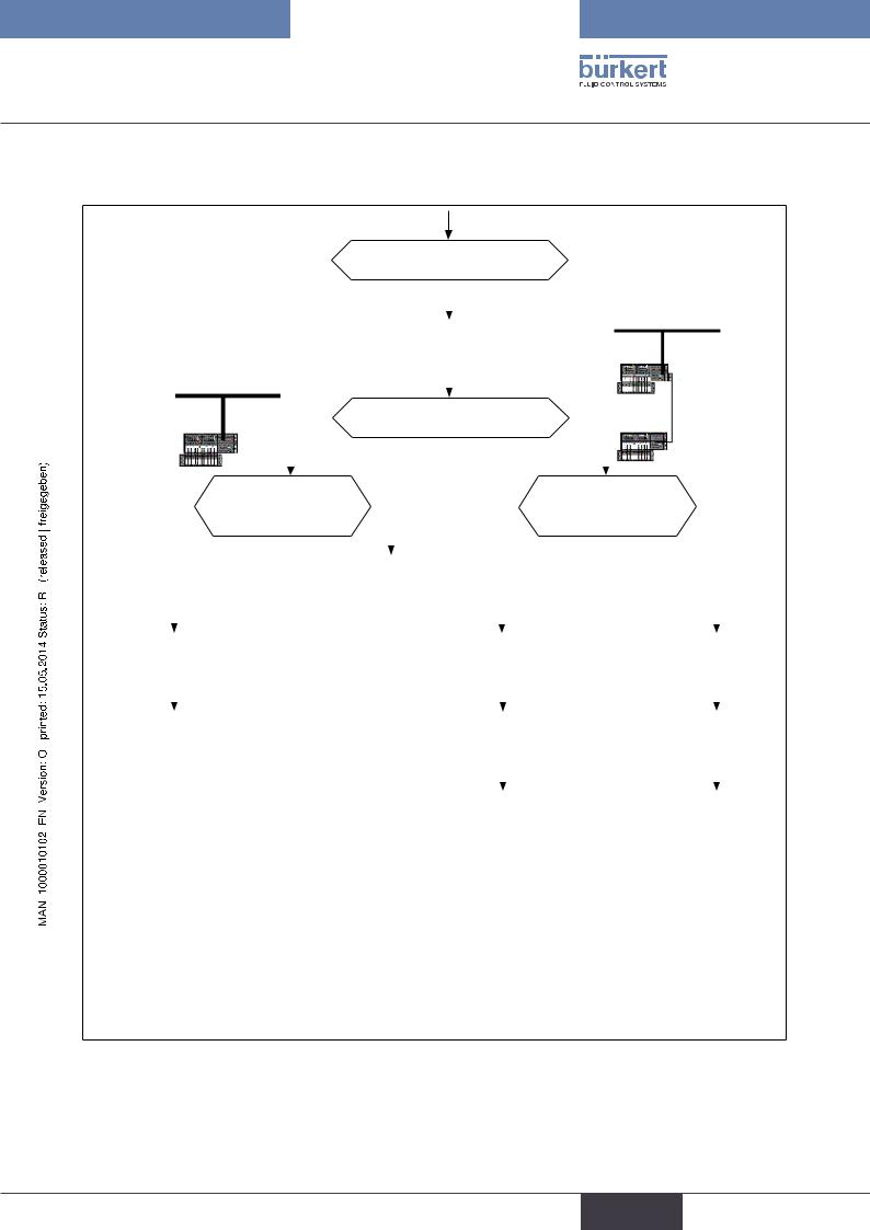
9.1.Representation of the PROFIBUS-DP communication process
Start
Read diagnosis |
|
Diagnosis OK ? |
No |
|
|
Yes |
|
Write parameter
Write configuration
Read diagnosis
Error ? |
Yes |
|
|
No |
|
Cyclical data exchange
The diagnostics routine is requested for as long as is necessary until the component responds and is not blocked by another master.
Master transmits parameterization data
-bus-specific data (e.g. signal monitoring)
-User-specific parameterization data (as required) errors are displayed in the diagnosis.
Master transmits required configuration
Required configuration is compared to actual configuration in slave
Errors are displayed in the diagnosis.
Master reads diagnosis.
If there is a parameterisation or configuration error, the communication is restarted from the beginning.
If the slave is in data exchange mode then a cyclical exchange of data takes place.
Figure 12: Simplified representation of the PROFIBUS-DP communication process
24
english
Type 8640
Configuration and parameter settings for PROFIBUS DP
9.2.Start-Up
Setting the PROFIBUS address via DIP switch
|
|
|
|
|
|
|
|
|
|
|
|
|
|
|
DP bus |
|
|
|
|
|
|
|
|
|
|
|
|
|
|
|
|
|
|
|
|||
|
|
|
|
|
|
|
|
|
|
|
|
|
|
|
|
|
|
|
|
|
|
|
|
|
|
|
|
DIP Switches |
|
|
|
|
|
|
|||
|
|
|
DP bus |
|
|
|
|
|
|
|
|
|
|
DP main |
||||
|
|
|
|
|
|
|
|
|
|
|
|
|
||||||
|
|
|
|
|
|
|
|
|
|
|
|
|
terminal |
|||||
|
|
|
|
|
|
|
|
|
|
|
|
|
|
|
|
|||
|
|
|
|
|
|
|
Are extension terminals (RIO) |
|
|
|
||||||||
|
|
|
|
|
|
|
|
|
|
|
|
|
||||||
DP main |
|
No |
|
|
|
present1) |
|
Yes |
|
RIO extension |
||||||||
|
|
|
|
|
|
|
|
|
|
|||||||||
|
|
|
|
|
|
|
|
|
|
|
|
|
||||||
terminal |
|
|
|
|
|
|
|
|
|
|
|
|
|
|
|
|
||
|
|
|
Should the default |
|
|
|
|
bytewise |
How should inputs / |
|
bitwise |
|||||||
|
|
|
input mode or filter be |
|
|
|
outputs be put |
|
||||||||||
|
|
|
|
|
|
|
|
|
|
|
|
|||||||
|
No |
modified |
|
Yes |
|
|
|
|
|
together2) |
|
|
|
|||||
|
|
|
|
|
|
|
|
|
|
|
|
|
|
|||||
|
|
|
|
|
|
|
|
|
|
|
|
|
|
|
|
|
|
|
|
|
|
|
|
|
|
|
|
|
|
|
|
|
|
|
|
|
|
|
|
|
|
|
|
Parameterization |
|
|
|
|
|
|
|
|
|
|||
|
|
|
|
|
|
|
|
|
|
|
|
|
|
|
|
|
|
|
|
|
|
|
|
|
|
|
|
|
|
|
|
|
|
|
|
|
|
|
|
|
|
|
|
|
|
|
|
|
|
|
|
|
|
|
|
|
Configuration |
|
Parameterization |
|
Parameterization |
|||
|
|
|
|
|
|
|
|
|
|
|
|
|
|
|
|
Example |
|
Configuration |
|
Configuration |
||
1 |
|
|
|
|
|
|
2 |
|
|
|
|
|
|
3 |
|
|
|
|
|
|
4 |
|
|
|
|
|
|
|
Example |
|
Example |
|||
|
|
|
||||
|
|
5 |
|
6 |
||
1)Extension terminals are connected to the valve terminal via the RIO interface
2)Advantage of bitwise distribution:
1.If the number of inputs or outputs does not correspond to the byte pattern then bits remain unused with bytewise configuration. For instance, with a valve terminal with 4 valves and a valve terminal with 10 valves that amounts to 10 bits with bytewise configuration (4+6 bits), because the first valve terminal requires 1 byte and the second one requires 2 bytes.
With bitwise distribution the outputs can be combined. This means that only 2 bytes are needed and 2 bits remain unused.
2.The bitwise composition means that the identifiers / slots (assignation in process image) can be selected at will in the configuration program.
Figure 13: Start-Up
25
english

Type 8640
Configuration and parameter settings for PROFIBUS DP
9.2.1.Parameterization without extension terminal (hex parameter / User_Prm_Data)
The default value for the parameterization is: |
||
• |
Extension terminal |
none |
• |
Input mode |
normal inputs |
• |
Filter |
ON |
The parameterization can be used to modify the settings selected for the input mode and the filter.
|
Bit 7 |
Bit 6 |
Bit 5 |
|
Bit 4 |
Bit 3 |
Bit 2 |
Bit 1 |
Bit 0 |
|
|
|
|
|
|
|
|
|
|
Byte |
Bus parameters (normal parameters) 7 bytes |
|
|
|
|
|
|
||
|
|
|
|
|
|
|
|
|
|
|
Lock_Rep |
Unlock_Re |
Sync_Req |
|
Freeze_Req |
WD_On |
reserved |
reserved |
reserved |
|
|
|
|
|
|
|
|
|
|
|
00 min TSDR and slave spec. data |
Slave being |
|
Slave being |
Signal moni- |
|
|
|
|
|
01 release for other masters |
operated in |
|
operated in |
toring |
|
|
|
|
|
10 lock for other masters |
Sync mode |
|
Freeze mode |
0: deactivated |
|
|
|
|
|
11 release for other masters |
|
|
|
1: activated |
|
|
|
|
|
|
|
|
|
|
|
|
|
|
2 |
WD_Fact_1 |
|
(range 1-255 signal monitoring in [s] = 10 ms x WD_Fact_1 x WD_Fact_2) |
|
|||||
|
|
|
|
|
|||||
3 |
WD_Fact_2 |
|
(range 1-255 signal monitoring in [s] = 10 ms x WD_Fact_1 x WD_Fact_2) |
|
|||||
|
|
|
|
||||||
4 |
TSDR |
|
(time in Tbits in which the slave may respond. At least 11 Tbit; 0 old value remains) |
||||||
|
|
|
|
|
|
||||
5 |
Ident_Number high byte |
(manufacturer identification 00 Hex) |
|
|
|
||||
|
|
|
|
|
|
||||
6 |
Ident_Number low byte |
(manufacturer identification 81 Hex) |
|
|
|
||||
|
|
|
|
|
|
||||
7 |
Group_Ident |
|
(For group generation; each bit represents one group.) |
|
|
||||
|
|
|
|
|
|
|
|||
|
|
|
User_Parm_Data (DPV1_Status) |
|
|
|
|||
|
|
|
|
|
|
|
|
|
|
8 |
|
|
|
DPV1_Status_1 |
|
|
|
|
|
|
|
|
|
|
|
|
|
|
|
9 |
|
|
|
DPV1_Status_2 |
|
|
|
|
|
|
|
|
|
|
|
|
|
|
|
10 |
|
|
|
DPV1_Status_3 |
|
|
|
|
|
|
|
|
|
|
|
|
|||
|
|
|
User_Prm_Data (user parameters) |
|
|
|
|||
|
|
|
|
|
|
|
|
|
|
11 |
See table below: |
|
|
|
|
|
|
|
|
|
|
|
|
|
|
|
|
|
|
Byte 11 User_Prm_Data (user parameters)
Input mode |
Input filter OFF |
Input filter ON |
|
|
|
no inputs |
04 hex |
44 hex |
|
|
|
normal inputs |
14 hex |
54 hex |
|
|
|
shifted inputs |
24 hex |
64 hex |
|
|
|
halved inputs |
34 hex |
74 hex |
|
|
|
For a description of the input modes, refer to Section “9.3. Mode inputs”Mode inputs".
Many configuration tools do not allow for direct access to bytes 1 to 7. For Siemens (Step 5 and Step 7) the parameters (Hex parameters) start at byte 8.
26
english
Type 8640
Configuration and parameter settings for PROFIBUS DP
9.2.2.Configuration of the valve terminal without extension terminals
The settings of the desired configuration, i.e. setting of various identifiers, is generally done with the help of the GSD file. Up to 7 identifiers (slots) can be assigned.
When the configuration is written, the number of input and output bytes is set in the process image and checked against permitted limits. By using different identifiers the user can assign the input and output bytes in the process image at will.
A valve terminal has a maximum of 32 inputs and a maximum of 24 outputs. This corresponds to a maximum of 4 input bytes and a maximum of 3 output bytes. For this reason never more than the above specified number of input / output bytes may be configured in the process image of a valve terminalHowever, taking the limits specified above into account (32 inputs, 24 outputs; 4 input bytes, 3 output bytes) it is possible to configure both less than, but also more than the number of input / output bytes that are actually physically present on the valve terminal.
Example:
Physically present |
Configuration |
Consequence |
|
|
|
|
1 bytes |
Only valves 1 to 8 can be addressed |
|
|
|
|
2 bytes |
Valves 1 to 16 can be addressed |
16 valves |
|
|
3 bytes |
Valves 1 to 16 can be addressed, |
|
|
|
1 byte remains unusable in process image |
|
|
|
|
4 bytes |
Configuration errors |
|
|
|
Manual configuration
If no GSD file is available the configuration must be performed manually. The following specifications apply. One configuration telegram can contain one or several identifications, whereby the user can make the necessary allocations at will. the identifications have the following structure:
Bit 7 |
Bit 6 |
|
Bit 5 - 4 |
Bit 3 - 0 |
|
|
|
|
|
Consistency |
bytes/words |
Input/Output |
Data length (number) |
|
0 = byte/word |
0 = bytes |
00 |
= spec. identifier format |
0000 = 1 byte/word |
1 = total length |
1 = words (2 bytes) |
01 |
= input |
... |
|
|
10 |
= output |
0010 = 3 bytes/words |
|
|
11 |
= input/output |
... |
|
|
|
|
1111 = 16 bytes/words |
|
|
|
|
|
|
|
|
|
|
Hex |
Decimal |
|
Description |
|
|
|
|
|
|
10 |
016 |
|
1 byte input; consistency via byte |
|
|
|
|
|
|
11 |
017 |
|
2 bytes input; consistency via byte |
|
|
|
|
|
|
12 |
018 |
|
3 bytes input; consistency via byte |
|
|
|
|
|
|
13 |
019 |
|
4 bytes input; consistency via byte |
|
|
|
|
|
|
20 |
032 |
|
1 byte output; consistency via byte |
|
|
|
|
|
|
21 |
033 |
|
2 bytes output; consistency via byte |
|
|
|
|
|
|
22 |
034 |
|
3 bytes output; consistency via byte |
|
|
|
|
|
|
00 |
000 |
|
Placeholder (empty position) |
|
|
|
|
|
|
27
english

Type 8640
Configuration and parameter settings for PROFIBUS DP
Example 1 - valve terminal with 16 valves (outputs) and 32 repeaters (inputs)
•PROFIBUS-DP address 4
•The valves 1-16 are assigned to outputs (PAA) bytes 11-12 in the process image.
•The repeaters 1-32 are assigned to inputs (PAE) bytes 20-23 in the process image.
•Mode: Normal input mode
•Input filter active
DIP Switches
1 |
|
2 |
|
3 |
|
|
4 |
|
5 |
6 |
|
7 |
8 |
|
|
|
|
|
|
|
|
|
|
|
|
|
|
|
|
OFF |
|
OFF |
|
ON |
|
OFF |
|
OFF |
|
OFF |
|
OFF |
OFF |
|
|
|
|
|
|
|
|
|
|
|
|
|
|||
User parameter byte 11 User_Prm_Data 54 hex |
|
|
|
|
|
|
||||||||
Configuration: |
|
|
|
|
|
|
|
|
|
|
|
|
|
|
|
|
|
|
|
|
|
|
|
|
|
|
|||
Byte No. (slot) |
|
|
|
1* (0**) |
|
|
|
2 (1) |
|
|
|
|||
|
|
|
|
|
|
|
|
|
||||||
Identification in Hex (Dec) |
|
13 (019) |
|
|
|
21 (033) |
|
|
||||||
|
|
|
|
|
|
|
|
|
|
|
|
|||
Process image output (PAA) |
|
|
|
|
|
|
|
11-12 |
|
|
|
|||
|
|
|
|
|
|
|
|
|
|
|||||
Process image input (PAE) |
|
20-23 |
|
|
|
|
|
|
|
|||||
|
|
|
|
|
|
|
|
|
|
|
|
|
|
|
* Standard |
|
|
|
|
|
|
|
|
|
|
|
|
|
|
** Siemens |
|
|
|
|
|
|
|
|
|
|
|
|
|
|
Allocation of inputs and outputs to control process image |
|
|
|
|
|
|
||||||||
|
|
|
|
|
|
|
|
|
|
|||||
|
|
Process image |
Inputs (PAE) |
|
|
|
|
|
|
|||||
Valve |
Valve |
Valve |
Valve |
Valve Valve |
Valve |
Valve |
Valve Valve |
Valve |
Valve |
Valve |
Valve |
Valve |
Valve |
Process image Outputs (PAA)
Figure 14: Allocation of inputs and outputs to control process image
28
english

Type 8640
Configuration and parameter settings for PROFIBUS DP
Example 2 - valve terminal with 16 valves (outputs) and 32 repeaters (inputs)
•PROFIBUS-DP address 5
•The valves 1-8 are assigned to outputs (PAA) byte 11 in the process image.
•The valves 9-16 are assigned to outputs (PAA) byte 20 in the process image.
•The repeaters 1-8 are assigned to inputs (PAE) byte 10 in the process image.
•The repeaters 9-16 are assigned to inputs (PAE) byte 15 in the process image.
•The repeaters 17-32 are assigned to inputs (PAE) bytes 20-21 in the process image.
•Mode: Normal input mode
•Input filter active
DIP Switches
1 |
|
2 |
|
3 |
4 |
5 |
6 |
7 |
8 |
||||
|
|
|
|
|
|
|
|
|
|
|
|
|
|
ON |
|
OFF |
|
ON |
|
OFF |
|
OFF |
|
OFF |
OFF |
|
OFF |
|
|
|
|
|
|
|
|
|
|
|
|
||
User parameter byte 11 User_Prm_Data 54 hex |
|
|
|
|
|
|
|
||||||
Configuration: |
|
|
|
|
|
|
|
|
|
|
|
|
|
|
|
|
|
|
|
|
|
|
|
|
|
|
|
Byte No. (slot) |
|
|
|
|
1 (0) |
|
2 (1) |
|
3 (2) |
4 (3) |
|
5 (4) |
|
|
|
|
|
|
|
|
|
|
|
|
|||
Identification in Hex (Dec) |
|
|
10 (016) |
|
10 (016) |
|
11 (017) |
20 (032) |
|
20 (032) |
|||
|
|
|
|
|
|
|
|
|
|
|
|||
Process image output (PAA) |
|
|
|
|
|
|
|
11 |
|
20 |
|||
|
|
|
|
|
|
|
|
|
|
|
|||
Process image input (PAE) |
|
|
10 |
|
15 |
|
20-21 |
|
|
|
|||
|
|
|
|
|
|
|
|
|
|
|
|
|
|
Allocation of inputs and outputs to control process image
Process image Inputs (PAE)
Valve
Valve
Valve
Valve
Valve
Valve
Valve
Valve
Valve
Valve
Valve
Valve
Valve
Valve
Valve
Valve
Process image Outputs (PPA)
Figure 15: |
Allocation of inputs and outputs to control process image |
29 |
english

Type 8640
Configuration and parameter settings for PROFIBUS DP
Example 3 - valve terminal with 16 valves (outputs) and 32 repeaters (inputs)
•PROFIBUS-DP address 6
•The valves 1-16 are assigned to outputs (PAA) bytes 11+12 in the process image.
•Repeaters 1, 3, 5, ... 15 are assigned to inputs (PAE) byte 10 in the process image.
•Repeaters 2, 4, 6, ... 16 are assigned to inputs (PAE) byte 16 in the process image.
•Repeaters 1, 17, 19, ... 31 are assigned to inputs (PAE) byte 11 in the process image.
•Repeaters 1, 18, 20, ... 32 are assigned to inputs (PAE) byte 17 in the process image.
•Mode: Shifted inputs
•Input filter active
DIP Switches
1 |
|
2 |
|
3 |
4 |
5 |
6 |
7 |
8 |
||||
|
|
|
|
|
|
|
|
|
|
|
|
|
|
OFF |
|
ON |
|
ON |
|
OFF |
|
OFF |
|
OFF |
OFF |
|
OFF |
|
|
|
|
|
|
|
|
|
|
|
|
||
User parameter byte 11 User_Prm_Data 64 hex |
|
|
|
|
|
|
|
||||||
Configuration: |
|
|
|
|
|
|
|
|
|
|
|
|
|
|
|
|
|
|
|
|
|
|
|
|
|
|
|
Byte No. (slot) |
|
|
|
|
1 (0) |
|
2 (1) |
|
3 (2) |
4 (3) |
|
5 (4) |
|
|
|
|
|
|
|
|
|
|
|
|
|||
Identification in Hex (Dec) |
|
|
10 (016) |
|
10 (016) |
|
10 (016) |
10 (016) |
|
21 (032) |
|||
|
|
|
|
|
|
|
|
|
|
|
|||
Process image output (PAA) |
|
|
|
|
|
|
|
|
|
11-12 |
|||
|
|
|
|
|
|
|
|
|
|
|
|||
Process image input (PAE) |
|
|
10 |
|
16 |
|
11 |
17 |
|
|
|||
|
|
|
|
|
|
|
|
|
|
|
|
|
|
Allocation of inputs and outputs to control process image
Process image Inputs (PAE)
Valve Valve |
Valve Valve Valve Valve |
Valve Valve Valve Valve |
Valve Valve |
Valve Valve Valve Valve |
|
|
|
Process image Outputs (PPA) |
|
|
|
|
30 |
Figure 16: |
Allocation of inputs and outputs to control process image |
|
|
|
|
|
english
Loading...