


 Loading...
Type 8692, 8693
Positioner TopControl
Process Controller TopControl
Electropneumatic positioner
Electropneumatic process controller
Operating Instructions
Bedienungsanleitung Manuel d‘ utilisation

We reserve the right to make technical changes without notice. Technische Änderungen vorbehalten.
Sous réserve de modifications techniques.
© 2008-2011 Bürkert Werke GmbH
Operating Instructions 1111/01_EU-ML_00806169 / Original DE

Type 8692, 8693
Table of contents
|
Positioner Type 8692, 8693 |
|
Table of Contents |
|
|
General information and safety instructions..................................................................................................... |
7 |
|
1. |
Operating instructions......................................................................................................................................................... |
8 |
2. |
Authorized use......................................................................................................................................................................... |
9 |
3. |
Basic safety instructions................................................................................................................................................. |
10 |
4. |
General Information........................................................................................................................................................... |
11 |
Description of system.................................................................................................................................................................... |
13 |
|
5. |
Function of the positioner and combination with valve types.................................................................... |
14 |
6. |
Structure of the positioner............................................................................................................................................. |
17 |
7. |
Type 8692 positioner with position controller...................................................................................................... |
20 |
8. |
Type 8693 positioner with process controller...................................................................................................... |
24 |
9. |
Interfaces of the positioner for the multipole model....................................................................................... |
28 |
10. |
Interfaces of the positioner for the models with cable gland..................................................................... |
29 |
11. |
Technical Data....................................................................................................................................................................... |
30 |
Control and display elements, operating modes........................................................................................... |
35 |
|
12. |
Control and display elements....................................................................................................................................... |
36 |
13. |
Operating modes................................................................................................................................................................. |
39 |
14. |
Operating Levels.................................................................................................................................................................. |
43 |
Installation................................................................................................................................................................................................ |
45 |
|
15. |
Installation............................................................................................................................................................................... |
47 |
16. |
Fluid connection................................................................................................................................................................... |
57 |
17. |
Electrical Connection 24 V DC with circular plug-in connector (multi-pole model)....................... |
59 |
18. |
Electrical Connection 24 V DC with Cable Gland.............................................................................................. |
67 |
19. |
Initial start-up........................................................................................................................................................................ |
72 |
3
english

Type 8692, 8693
Table of contents
Start-up and operation of the position controller Type 8692......................................................... |
77 |
|
20. |
Starting up and installing the position controller Type 8692 ....................................................................... |
79 |
21. |
Operation of the position controller .......................................................................................................................... |
87 |
22. |
Configuring the auxiliary functions ............................................................................................................................ |
92 |
Start-up and operation of the position controller Type 8693...................................................... |
125 |
|
23. |
Starting up and setting up the process controller Type 8693 .................................................................. |
127 |
24. |
Operation of the process controller ....................................................................................................................... |
149 |
25. |
Auxiliary functions for the process controller ................................................................................................... |
154 |
PROFIBUS-DP............................................................................................................................................................................................. |
173 |
|
26. |
General Information ........................................................................................................................................................ |
174 |
27. |
Technical Data .................................................................................................................................................................... |
174 |
28. |
Safety Settings if the Bus Fails . ............................................................................................................................... |
175 |
29. |
Interfaces .............................................................................................................................................................................. |
175 |
30. |
Electrical connections .................................................................................................................................................... |
176 |
31. |
Settings on the positioner . .......................................................................................................................................... |
179 |
32. |
Functional Deviations from the Standard Model ............................................................................................. |
184 |
33. |
Configuration in the Profibus - DP Master . ........................................................................................................... |
184 |
34. |
Bus Status Display . ......................................................................................................................................................... |
187 |
35. |
Configuration with Siemens Step7 ......................................................................................................................... |
188 |
DeviceNet |
.................................................................................................................................................................................................... |
191 |
36. ........................................................................................................................................................ |
General Information |
193 |
37. .......................................................................................................................................................... |
Definition of Terms |
193 |
38. .................................................................................................................................................................... |
Technical Data |
194 |
39. ................................................................................................................................ |
Safety Settings if the Bus Fails |
195 |
40. .............................................................................................................................................................................. |
Interfaces |
195 |
41. .................................................................................................................................................... |
Electrical connections |
196 |
42. .................................................................................................... |
Settings on the positioner in the Main Menu |
200 |
43. ............................................................................................. |
Functional Deviations from the Standard Model |
203 |
44. ......................................................................................................................... |
Configuration of the Process Data |
204 |
4
english

Type 8692, 8693
Table of contents
45. |
Bus Status Display.......................................................................................................................................................... |
207 |
46. |
Configuration Example 1.............................................................................................................................................. |
208 |
47. |
Configuration Example 2.............................................................................................................................................. |
211 |
Maintenance and troubleshooting.............................................................................................................................. |
213 |
|
48. |
Maintenance........................................................................................................................................................................ |
214 |
49. |
Error messages and malfunctions Type 8692.................................................................................................. |
216 |
50. |
Error messages and malfunctions Type 8693.................................................................................................. |
218 |
Disassembly............................................................................................................................................................................................ |
223 |
|
51. |
Disassembly........................................................................................................................................................................ |
224 |
Packaging, storage and disposal.................................................................................................................................. |
227 |
|
52. |
Packaging and transport.............................................................................................................................................. |
228 |
53. |
Storage.................................................................................................................................................................................. |
228 |
54. |
Disposal................................................................................................................................................................................. |
228 |
Accessories............................................................................................................................................................................................ |
229 |
|
55. |
Accessories......................................................................................................................................................................... |
230 |
General Rules (Appendix)......................................................................................................................................................... |
231 |
|
56. |
Selection criteria for continuous valves............................................................................................................... |
232 |
57. |
Properties of PID controllers...................................................................................................................................... |
234 |
58. |
Adjustment rules for PID controllers..................................................................................................................... |
240 |
Operating structure of the positioner (Appendix).................................................................................... |
245 |
|
59. |
Operating Structure........................................................................................................................................................ |
246 |
Tables for customer-specific settings (appendix)..................................................................................... |
253 |
|
60. |
Settings of the freely programmable characteristic Type 8692 and Type 8693............................. |
254 |
61. |
Set parameters of the process controller Type 8693................................................................................... |
255 |
Mastercode (Appendix).............................................................................................................................................................. |
257 |
|
62. |
Mastercode.......................................................................................................................................................................... |
258 |
5
english

Type 8692, 8693
Table of contents
6
english

Type 8692, 8693
General information and safety instructions
Table of Contents
1. |
OperaTIng instructions........................................................................................................................................................ |
8 |
|
|
1.1. |
Symbols....................................................................................................................................................................................... |
8 |
2. |
Authorized use.............................................................................................................................................................................. |
9 |
|
|
2.1. |
restrictions................................................................................................................................................................................ |
9 |
3. |
Basic safety instructions............................................................................................................................................... |
10 |
|
4. |
General InformaTIOn............................................................................................................................................................. |
11 |
|
|
4.1. |
Contact address................................................................................................................................................................... |
11 |
|
4.2. |
Warranty.................................................................................................................................................................................... |
11 |
|
4.3. |
Master code............................................................................................................................................................................ |
11 |
|
4.4. |
Information on the internet............................................................................................................................................ |
11 |
7
english

Type 8692, 8693
General Information
Safety Instructions
1.Operating instructions
The operating instructions describe the entire life cycle of the device. Keep these instructions in a location which is easily accessible to every user and make these instructions available to every new owner of the device.
 Warning!
The operating instructions contain important safety information!
Failure to observe these instructions may result in hazardous situations.
• The operating instructions must be read and understood.
1.1.Symbols
 Danger!
Warns of an immediate danger!
• Failure to observe the warning may result in a fatal or serious injury.
 Warning!
Warns of a potentially dangerous situation!
• Failure to observe the warning may result in serious injuries or death.
 Caution!
Warns of a possible danger!
• Failure to observe this warning may result in a moderately severe or minor injury.
Note!
Warns of damage to property!
• Failure to observe the warning may result in damage to the device or the equipment.
 Indicates important additional information, tips and recommendations.
 refers to information in these operating instructions or in other documentation.
→→designates a procedure which you must carry out.
8
english
Type 8692, 8693
General Information
Safety Instructions
2.Authorized use
Incorrect use of the positioner Type 8692 and Type 8693 may be a hazard to people, nearby equipment and the environment.
The device is designed to be mounted on pneumatic actuators of process valves for the control of media.
•Do not expose the device to direct sunlight.
•Use according to the permitted data, operating conditions and conditions of use specified in the contract documents and operating instructions, as described in chapter “Description of system” - “11. Technical data“ in this manual and in the valve manual for the respective pneumatically actuated valve.
•The device may be used only in conjunction with third-party devices and components recommended and authorised by Bürkert.
•In view of the large number of options for use, it is essential prior to installation to study and, if necessary, to test whether the positioner is suitable for the specific application case.
•Correct transportation, correct storage and installation and careful use and maintenance are essential for reliable and problem-free operation.
•Use the positioner Type 8692 and Type 8693 only as intended.
2.1.Restrictions
If exporting the system/device, observe any existing restrictions.
9
english
Type 8692, 8693
General Information
Safety Instructions
3.Basic safety instructions
These safety instructions do not make allowance for any
•contingencies and events which may arise during the installation, operation and maintenance of the devices.
•local safety regulations; the operator is responsible for observing these regulations, also with reference to the installation personnel.
 Danger!
Danger – high pressure!
• Before loosening the lines and valves, turn off the pressure and vent the lines.
Risk of electric shock!
• Before reaching into the device or the equipment, switch off the power supply and secure to prevent reactivation!
• Observe applicable accident prevention and safety regulations for electrical equipment!
General hazardous situations.
To prevent injury, ensure that:
• the system cannot be activated unintentionally.
• Installation and repair work may be carried out by authorised technicians only and with the appropriate tools.
• After an interruption in the power supply or pneumatic supply, ensure that the process is restarted in a defined or controlled manner.
• The device may be operated only when in perfect condition and in consideration of the operating instructions.
• The general rules of technology apply to application planning and operation of the device.
• Do not put any loads on the body (e.g. by placing objects on it or standing on it).
• Do not make any external modifications to the device bodies. Do not paint the body parts or screws.
Note!
Electrostatic sensitive components / modules!
• The device contains electronic components which react sensitively to electrostatic discharge (ESD). Contact with electrostatically charged persons or objects is hazardous to these components. In the worst case scenario, they will be destroyed immediately or will fail after start-up.
•Observe the requirements in accordance with EN 100 015 - 1 and 5 - 2 to minimise or avoid the possibility of damage caused by sudden electrostatic discharge!
•Also ensure that you do not touch electronic components when the power supply voltage is present!
The positioners Type 8692 and Type 8693 were developed with due consideration given to the accepted safety rules and is state-of-the-art. However, dangers can still arise.
Failure to observe this operating manual and its operating instructions as well as unauthorized tampering with the device release us from any liability and also invalidate the warranty covering the devices and accessories!
10
english
Type 8692, 8693
General Information
Safety Instructions
4.General Information
4.1.Contact address
Germany
Bürkert Fluid Control System
Sales Center
Chr.-Bürkert-Str. 13-17
D-74653 Ingelfingen
Tel. + 49 (0) 7940 - 10 91 111
Fax + 49 (0) 7940 - 10 91 448
E-mail: info@de.buerkert.com
International
Contact addresses can be found on the final pages of the printed operating instructions.
And also on the Internet at:
www.burkert.com
4.2.Warranty
The warranty is only valid if the positioner Type 8692 and Type 8693 is used as intended in accordance with the specified application conditions.
4.3.Master code
Operation of the device can be locked via a freely selectable user code. In addition, there is a non-changeable master code with which you can perform all operator control actions on the device. This 4-digit master code can be found in the Appendix of these operating instructions in the chapter entitled “Master code”.
If required, cut out the code and keep it separate from these operating instructions.
4.4.Information on the internet
The operating instructions and data sheets for Type 8694 can be found on the Internet at:
www.burkert.com
11
english

Type 8692, 8693
General Information
Safety Instructions
12
english

Type 8692, 8693
Description of system
Table of Contens
5. |
Function of the positioner and combinaTIOn with valVE.Types................................................. |
14 |
|
|
5.1. Models of the positioner................................................................................................................................................. |
15 |
|
|
5.2. Features of the valve types............................................................................................................................................ |
16 |
|
6. |
Structure of the positioner........................................................................................................................................ |
17 |
|
|
6.1. |
representation...................................................................................................................................................................... |
17 |
|
6.2. |
Features.................................................................................................................................................................................... |
18 |
|
6.3. Function diagram of the positioner with single-acting actuator................................................................ |
19 |
|
7. |
Type 8692 Positioner with position controller......................................................................................... |
20 |
|
|
7.1. |
Schematic representation of the positioner Type 8692................................................................................. |
21 |
|
7.2. |
Properties of the position controller software..................................................................................................... |
22 |
8. |
Type 8693 positioner with process controller......................................................................................... |
24 |
|
|
8.1. |
Schematic representation of the process control............................................................................................. |
25 |
|
8.2. |
Functions of the process controller software...................................................................................................... |
26 |
9. |
InterfACES.OF.The positioner for the mulTIPOLE.MODEL..................................................................... |
28 |
|
10. |
InterfACES.OF.The positioner for the models with cable gland.............................................. |
29 |
|
11. |
Technical DaTA............................................................................................................................................................................. |
30 |
|
|
11.1. Safety positions after failure of the electrical or pneumatic auxiliary power..................................... |
30 |
|
|
11.2. Factory settings of the positioner.............................................................................................................................. |
31 |
|
|
11.3. Specifications of the positioner.................................................................................................................................. |
32 |
|
|
|
11.3.1. Conformity................................................................................................................................................. |
32 |
|
|
11.3.2. Standards.................................................................................................................................................. |
32 |
|
|
11.3.3. Operating conditions.............................................................................................................................. |
32 |
|
|
11.3.4. Mechanical data....................................................................................................................................... |
32 |
|
|
11.3.5. Electrical data........................................................................................................................................... |
32 |
|
|
11.3.6. Pneumatic Data........................................................................................................................................ |
33 |
|
|
11.3.7. Type label................................................................................................................................................... |
34 |
13
english

Type 8692, 8693
Description of system
5.Function of the positioner and combination with valve types
Positioners Type 8692 and Type 8693 are electropneumatic positioner for pneumatically actuated control valves with single-acting or double-acting actuators.
Together with the pneumatic actuator the positioner forms an optical and functional unit.
The control valve systems can be used for a wide range of control tasks in fluid technology and, depending on the application conditions, different process valves belonging to series 2300 or 2103 from the Bürkert range can be combined with the positioner. Angle-seat valves, diaphragm valves or ball valves fitted with a control cone are suitable.
“Figure 1” shows an overview of the possible combinations of positioner and different pneumatically actuated valves. Different actuator sizes and valve nominal widths, not illustrated here, are available for each type. More precise specifications can be found on the respective data sheets. The product range is being continuously expanded.
Positioner
Type 8692
Type 8693
with diaphragm valve Type 2103
with slanted seat valve Type 2300
Figure 1: Overview of possible combinations
14
english

Type 8692, 8693
Description of system,
5.1.Models of the positioner
The positioner is available in 2 versions:
Type 8692 - Positioner with positioning control
The position of the actuator (stroke) is regulated according to the position set-point value. The position set-point value is specified by an external uniform signal (or via field bus).
Type 8693 - Positioner with process control
The positioner is linked to a control circuit. The position set-point value of the valve is calculated from the process set-point value and the actual process value via the control parameters (PID controller). The process set-point value can be set by an external signal.
Pneumatically actuated piston actuators and rotary actuators can be used as a actuator. Both single-acting and double-acting actuators are offered in combination with the positioner.
For single-acting actuators, only one chamber is aerated and deaerated during actuation. The generated pressure works against a spring. The piston moves until there is an equilibrium of forces between compressive force and spring force.
For double-acting actuators the chambers on both sides of the piston are pressurised. In this case, one chamber is aerated when the other one is deaerated and vice versa. In this design, no spring is installed in the actuator.
15
english
Type 8692, 8693
Description of system
5.2.Features of the valve types
|
Slanted seat control |
Diaphragm valves |
Ball valves |
Flap valves |
||||
|
valves / screw-down |
|
|
|
|
|
|
|
|
stop globe control |
|
|
|
|
|
|
|
|
valves |
|
|
|
|
|
|
|
|
|
|
|
|
||||
Types |
• 2702 |
• 2730 |
• 2652 |
• 2672 |
||||
|
• 2712 |
• 2103 |
• 2655 |
• 2675 |
||||
|
• 2300 |
• 2731 |
• 2658 |
|
|
|||
|
• 2301 |
|
|
|
|
|
|
|
|
|
|
|
|
|
|
|
|
Features |
• |
incoming flow under |
• |
medium is hermeti- |
• |
scrapable |
• |
unaffected by |
|
|
seat |
|
cally separated from |
• minimum dead |
|
contamination |
|
|
|
|
|
the actuator and |
|
|
||
|
• |
closes smoothly |
|
|
space |
• |
little pressure loss |
|
|
|
environment |
|
|||||
|
|
|
|
|
|
|
compared to other |
|
|
• |
straight flow path of |
|
|
• |
unaffected by |
|
|
|
• |
cavity-free and self- |
|
valve types |
||||
|
|
the medium |
|
contamination |
|
|||
|
|
|
draining body design |
|
|
|
||
|
|
|
|
|
|
• |
inexpensive |
|
|
• |
self-adjusting |
|
|
• |
little pressure loss |
||
|
• |
any flow direction |
|
|
||||
|
|
stuffing box for high |
|
compared to other |
• |
low construction |
||
|
|
|
with low-turbulence |
|
||||
|
|
leak-tightness |
|
|
valve types |
|
volume |
|
|
|
|
flow |
|
|
|||
|
|
|
|
|
|
|
|
|
|
|
|
• |
steam-sterilizable |
• |
seat and seal can |
|
|
|
|
|
|
be exchanged in the |
|
|
||
|
|
|
|
|
|
|
|
|
|
|
|
• |
CIP-compliant |
|
three-piece ball valve |
|
|
|
|
|
• |
closes smoothly |
|
when installed |
|
|
|
|
|
|
|
|
|
||
|
|
|
• |
actuator and dia- |
Information |
|
|
|
|
|
|
|
phragm can be |
Can be used as |
|
|
|
|
|
|
|
removed when the |
process controller only |
|
|
|
|
|
|
|
body is installed |
|
|
|
|
|
|
|
|
|
|
|
|
|
Typical |
• |
water, steam and |
• |
neutral gases and |
• |
neutral gases and |
• |
neutral gases and |
media |
|
gases |
|
liquids |
|
liquids |
|
liquids |
|
• |
alcohols, oils, pro- |
• |
contaminated, |
• |
clean water |
• |
slightly aggressive |
|
|
pellants, hydraulic |
|
abrasive and |
• |
slightly aggressive |
|
media |
|
|
fluids |
|
aggressive media |
|
|
||
|
|
|
|
media |
|
|
||
|
|
|
|
|
|
|
|
|
|
• |
salt solutions, lyes |
• |
media of higher |
|
|
|
|
|
|
(organic) |
|
viscosity |
|
|
|
|
|
• |
solvents |
|
|
|
|
|
|
|
|
|
|
|
|
|
|
|
Table 1: |
Features of the valve types |
|
|
|
|
|
|
|
16
english

Type 8692, 8693
Description of system,
6.Structure of the positioner
The positioners Type 8692 and Type 8693 consist of the micro-processor controlled electronics, the position measuring system and the control system.
The appliance is designed using three-wire technology. Operation of the positioner is controlled by four keys and a 128x64 dot matrix graphic display.
The pneumatic control system for single or double-acting actuators consists of two or four solenoid valves.
6.1.Representation
 Transparent cap

Body casing
Pressure limiting valve 
 (for protection against too


 high internal pressure in
case of error)
Electrical connection module |
Exhaust air connection |
Pilot air port |
(here with circular plug-in connectors) |
(label: 3) |
(label: 1) |
 Control module with
display and keys
(View without transparent cap)
Additional
Exhaust air connection (connection: 3.1)
only with Type 23xx and 2103
with pilot-operated control system for high air output (actuator size ø 125 / 130)
Figure 2: |
Structure |
17
english

Type 8692, 8693
Description of system
6.2.Features
•Models.
for single-acting or double-acting valve actuators.
•Position measuring system.
Non-contact and therefore non-wearing position measuring system.
•Microprocessor-controlled electronics. for signal processing, control and valve control.
•Control module.
Operation of the device is controlled by four keys. The 128x64 dot matrix graphics display enables you to display the set-point or actual value and to configure and parameterize via menu functions.
•Control system.
The control system consists of 2 solenoid valves for single-acting actuators or four solenoid valves for doubleacting actuators. In single-acting actuators, one valve serves for the aeration and another for the deaeration
of the pneumatic piston actuator. Double-acting actuators feature 2 valves for aeration and deaeration. The solenoid valves operate according to the rocker principle and are controlled with a PWM voltage via the controller. Doing so achieves a higher flexibility with regard to actuator volume and final control speed. The directaction model has an orifice of DN 0.6. On larger pneumatic actuators the solenoid valves feature diaphragm reinforcers to increase the maximum flow and therefore improve the dynamics (DN 2.5).
• Position feedback (optional).
One inductive proximity switch.
When the valve reaches an upper or a lower position, this can be relayed e.g. to a PLC via binary outputs. By means of set-screws, the operator can change the inductive proximity switch or limit positions.
• Pneumatic interfaces
1/4” connections with different thread forms (G, NPT)
Hose plug-in connection
• Electrical interfaces
Circular plug-in connector or cable gland
•Body.
The body of the positioner is protected from excessively high internal pressure, e.g. caused by leaks, by a
18 pressure limiting valve.
english
Type 8692, 8693
Description of system,
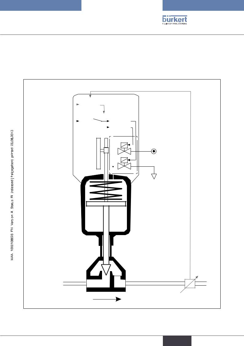
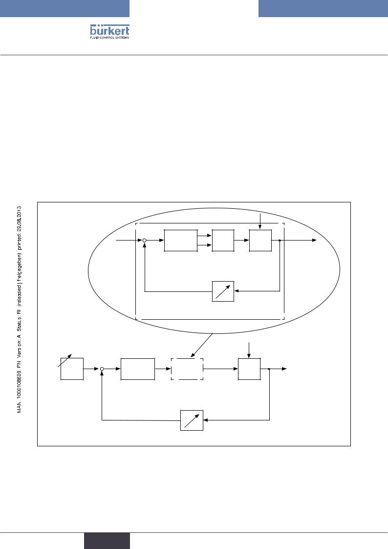
6.3.Function diagram of the positioner with singleacting actuator
The black lines describe the function of the position controller (Type 8692). The process controller (Type 8693) includes the position controller and the functions which are illustrated in grey.
|
|
|
|
|
Process actual value |
|||||||||||||
|
Process set-point |
|
|
|
|
|
|
|
|
|
|
|
|
|
|
|
|
|
|
|
|
|
|
|
|
|
|
|
|
|
|
|
|
|
|
|
|
|
value |
|
|
Process |
|
Nominal position |
||||||||||||
|
|
|
|
|
||||||||||||||
|
|
|
|
controller |
|
|||||||||||||
|
External position |
|
|
|
|
|
|
|
|
|
|
|
|
|
||||
|
|
|
|
|
|
|
|
|
|
|
|
|
|
|
|
|
|
|
|
set-point value |
|
|
|
|
|
|
|
|
|
|
|
|
|
|
|
|
|
|
|
|
|
|
|
|
|
|
|
Position |
|
|
||||||
|
|
|
|
|
|
|
|
|
|
|
|
|
||||||
|
|
|
|
|
|
|
|
|
|
|
|
|
||||||
|
|
|
|
Actual |
|
|
|
|
controller |
|
|
|||||||
|
|
|
|
|
|
|
|
|
|
|||||||||
|
Positioner |
|
|
position |
|
|
|
|
|
|
|
|
|
|
|
|
||
|
|
|
|
Control system |
||||||||||||||
|
|
|
|
|
|
|
|
|
|
|
||||||||
|
|
|
|
|
|
|
|
|
|
|
||||||||
|
|
Position |
1 |
|
|
|
|
|||||||||||
|
|
|
|
|
|
|||||||||||||
|
|
|
|
|
|
|
|
|
|
|
|
|
||||||
|
|
|
|
|
|
|
|
|
|
|
|
|
||||||
|
|
measuring |
|
2 |
|
|
|
|
||||||||||
|
|
system |
|
|
|
|
|
|
|
|
|
|
|
|||||
|
|
|
|
|
|
|
|
|
|
|
|
|
|
|
|
|
|
|
|
|
|
|
|
|
|
|
|
|
|
|
|
|
|
|
|
|
|
|
|
|
|
|
|
|
|
|
|
|
|
|
|
|
|
|
|
|
|
|
|
|
|
|
|
|
|
|
|
|
|
|
|
|
|
|
|
Pneumatic actuator (single-acting)
Valve
Control system
1:Aeriation valve
2:Bleed valve
Compressedair supply
Exhaust air
Sensor
Process actual value (flow, pressure, level, temperature, et cetera.)
Figure 3: Function diagram
19
english
Type 8692, 8693
Description of system
7.Type 8692
Positioner with position controller
The position measuring system records the current position (POS) of the pneumatic actuator. The position controller compares this actual position value with the set-point value (CMD), which is definable as norm signal. In case of a control deviation (Xd1), a pulse-width modulated voltage signal is sent to the control system as a manipulated variable. If there is a positive control difference in single-acting actuators, the air inlet valve is controlled via output B1. If the control difference is negative, the bleed valve is controlled via output E1. In this way the position of the actuator is changed until control difference is 0. Z1 represents a disturbance variable.
|
|
|
|
Z1 |
|
|
B1 |
PK |
|
CMD |
|
Xd1 |
Valve opening |
|
+ |
- |
E1 |
|
|
|
|
|
||
Position set- |
|
Positioner |
Control system |
Continuous |
point value |
|
|
solenoid valves |
valve |
|
|
POS |
|
|
|
Position control circuit |
Position measuring |
||
|
|
|
||
Figure 4: Signal flow plan of position controller
20
english
Type 8692, 8693
Description of system,
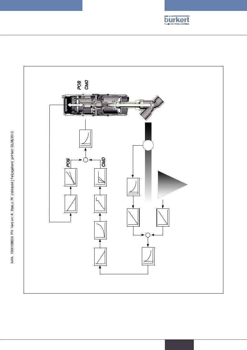
7.1.Schematic representation of the positioner Type 8692
INPUT
TEMP
CMD
POS
|
|
X.CONTROL |
DBND |
POS |
|
|
CMD |
|
|
X.LIMIT |
X.TIME |
|
|
DIR.ACT |
CUTOFF |
|
|
|
CHARACT |
|
|
|
SPLTRNG |
... 20 mA |
... 20 mA |
... 10 V ... 5 V |
DIR.CMD |
4 |
0 |
0 0 INP |
|
Figure 5: |
Schematic representation of position control |
21 |
english
Type 8692, 8693
Description of system
7.2.Properties of the position controller software
Additional function |
Action |
|
|
|
|
Position controller with additional function |
|
|
|
|
|
Sealing function |
Valve closes tight outside the control range. Specifi- |
|
CUTOFF |
|
cation of the value (in %), from which the actuator is |
|
completely deaerated (when 0%) or aerated (when |
|
|
|
|
|
|
100%). |
|
|
|
Stroke limit |
|
Mechanical valve piston movement only within a |
X.LIMIT |
|
defined stroke range |
|
|
|
Signal range splitting |
Splitting of the standard signal range to two or more |
|
SPLTRNG |
|
positioners |
|
|
|
|
|
|
Correction line to adjust the operating characteristic |
The operating characteristic can be linearized |
|
CHARACT |
|
|
Insensitivity range |
The position controller is initially actuated from a |
|
X.CONTROL |
control difference to be defined |
|
|
||
|
|
|
Effective direction of the controller nominal value |
Reversal of the effective direction of the nominal value |
|
DIR.CMD |
|
|
Safety position |
Definition of the safety position |
|
SAFEPOS |
|
|
|
|
|
Limit of the control speed |
Input of the opening and closing time for the entire |
|
X.TIME |
|
stroke |
|
|
|
Effective direction of the actuator |
Adjustment of the effective direction between aeration |
|
DIR.ACT |
|
state of the actuator and the actual position |
|
|
|
|
|
|
Signal level error detection |
Check the input signals for sensor break. |
|
SIG.ERROR |
Warning output on the display and start up of the |
|
|
|
safety position (if selected) |
|
|
|
Binary input |
|
Switch over AUTOMATIC-MANUAL or |
BINARY. IN |
|
Start up of the safety position |
|
|
|
Analogue feedback (option) |
Status signal set-point or actual value |
|
OUTPUT |
|
|
|
|
|
2 binary outputs (option) |
Output of two selectable binary values. |
|
OUTPUT |
|
|
User calibration |
Change to the factory calibration of the signal input |
|
CAL.USER |
|
|
|
|
|
Table 2: |
Functions position controller |
|
22
english
Type 8692, 8693
Description of system,
Hierarchical control concept for easy control on the following levels |
||
|
|
|
Process control |
On this level switch between AUTOMATIC and |
|
|
|
MANUAL mode. |
|
|
|
Configuration and parameterisation |
On this level specify certain basic functions during |
|
|
|
start-up and, if required, configure additional functions |
|
|
|
Table 3: |
Position controller - hierarchical control concept |
|
23
english
Type 8692, 8693
Description of system
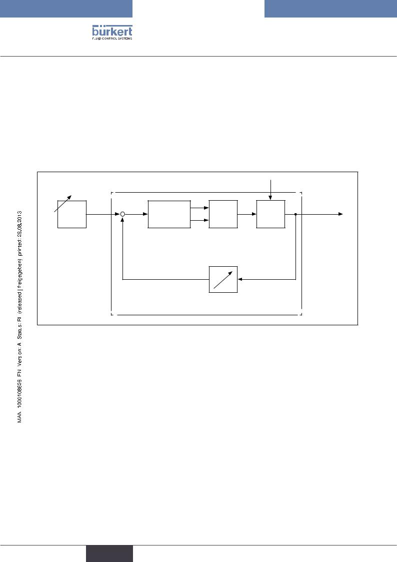
8.Type 8693
positioner with process controller
If the positioner is operated with process controller Type 8693, the aforementioned position control becomes the subordinate auxiliary control circuit; this results in a cascade control. The process controller in the main control circuit of the positioner has a PID function. The process set-point value (SP) is specified as set-point value and compared with the actual value (PV) of the process variable to be controlled. The position measuring system records the current position (POS) of the pneumatic actuator. The position controller compares this actual position value with the set-point value (CMD), which is determined by the process controller. In case of a control deviation (Xd1), a pulse-width modulated voltage signal is sent to the control system as a manipulated variable. If there is a positive control difference in single-acting actuators, the air inlet valve is controlled via output B1. If the control difference is negative, the bleed valve is controlled via output E1. In this way the position of the actuator is changed until control difference is 0. Z2 represents a disturbance variable.
|
|
|
|
|
|
Z1 |
|
|
CMD |
Xd1 |
|
B1 |
PK |
Valve |
|
|
|
E1 |
|||||
|
+ |
- |
|
|
opening |
||
|
|
|
|
||||
|
|
Position |
Control system |
Continuous |
|||
|
|
controller |
solenoid valves |
valve |
|||
|
|
|
|
POS |
|
|
|
|
|
|
|
|
Position measuring |
||
|
|
Position control circuit |
|
||||
|
|
|
|
|
Z2 |
||
SP |
Xd2 |
CMD |
Position |
Valve |
Process variable |
||
opening |
|||||||
|
|||||||
+ |
- |
|
control |
|
|
||
|
circuit |
|
|
||||
|
|
Process |
|||||
Process set-point |
Process controller |
|
|
||||
|
|
|
|
|
|
||
value |
|
|
|
|
|
|
|
|
|
PV |
|
|
|
|
|
|
|
|
Transmitter |
|
|||
Figure 6: Signal flow plan of process controller
24
english
Type 8692, 8693
Description of system,
8.1.Schematic representation of the process control
TEMP
SP
PV
CMD
POS
|
|
X.CONTROL |
DBDx |
|
|
|
Q |
...204 mA ...200 mA ...100 V ...50 V |
POS |
X.LIMIT |
+ |
CMD |
X.TIME |
FILTER |
|
|
|
|
- |
|
|
|
|
|
|
|
|
DIR.ACT |
|
|
CHARACT CUTOFF |
PV SCALE PV PV |
- |
+ |
SP SP SCALE SP |
|
|
|
|
DIR.CMD |
|
|
|
P.CONTROL PARAMETER SETUP |
Figure 7: Schematic representation of process control
25
english

Type 8692, 8693
Description of system
8.2.Functions of the process controller software
Additional function |
Action |
|
|
|
|
Position controller with additional function |
|
|
|
|
|
Sealing function |
Valve closes tight outside the control range. Specification |
|
CUTOFF |
|
of the value (in %), from which the actuator is completely |
|
deaerated (when 0%) or aerated (when 100%). |
|
|
|
|
Stroke limit |
|
Mechanical valve piston movement only within a defined |
X.LIMIT |
|
stroke range |
|
|
|
|
|
|
Correction line to adjust the operating |
The operating characteristic can be linearized |
|
characteristic |
|
|
CHARACT |
|
|
Insensitivity range |
The position controller is initially actuated from a control |
|
X.CONTROL |
difference to be defined |
|
|
||
|
|
|
Effective direction of the controller nominal value |
Reversal of the effective direction of the nominal value |
|
DIR.CMD |
|
|
|
|
|
Safety position |
Definition of the safety position |
|
SAFEPOS |
|
|
|
|
|
Limit of the control speed |
Input of the opening and closing time for the entire stroke |
|
X.TIME |
|
|
|
|
|
Effective direction of the actuator |
Adjustment of the effective direction between aeration |
|
DIR.ACT |
|
state of the actuator and the actual position |
|
|
|
Signal level error detection |
Check the input signals for sensor break. |
|
SIG.ERROR |
Warning output on the display and start up of the safety |
|
|
|
position (if selected) |
|
|
|
Binary input |
|
Switch over AUTOMATIC-MANUAL or |
BINARY. IN |
|
Start up of the safety position |
Analogue feedback (option) |
Status signal set-point or actual value |
|
OUTPUT |
|
|
|
|
|
2 binary outputs (option) |
Output of two selectable binary values. |
|
OUTPUT |
|
|
User calibration |
Change to the factory calibration of the signal input |
|
CAL.USER |
|
|
|
|
|
Table 4: |
Functions position controller |
|
26
english
Type 8692, 8693
Description of system,
Additional function |
Action |
||
|
|
||
Process controller with additional function |
|
||
|
|
||
Controller structure |
PID |
||
P.CONTROL |
|
||
|
|
||
Adjustable parameters |
Proportional coefficient, reset time, hold-back time and |
||
P.CONTROL - PARAMETER |
operating point |
||
|
|||
Scalable inputs |
Position of the decimal points, lower and upper scale |
||
P.CONTROL - SETUP |
values of the actual process value and the process set- |
||
point value |
|||
|
|
||
Selection of the nominal value specification |
Set-point value specification either via standard signal |
||
P.CONTROL - SETUP - SP INPUT |
input or via keys |
||
|
|||
|
|
||
Process characteristic linearization |
Function for automatic linearization of the process |
||
P.Q‘LIN |
|
characteristics |
|
|
|
||
|
|
||
Process controller optimization |
Function for automatic optimization of the process con- |
||
P.TUNE |
|
troller parameters |
|
|
|
||
|
|
|
|
Table 5: |
Functions process controller |
|
|
Hierarchical control concept for easy control on the following levels |
||
|
|
|
Process control |
On this level switch between AUTOMATIC and MANUAL |
|
|
|
mode. |
|
|
|
Configuration and parameterization |
On this level specify certain basic functions during start- |
|
|
|
up and, if required, configure additional functions |
|
|
|
Table 6: |
Process controller - hierarchical control concept |
|
27
english

Type 8692, 8693
Description of system
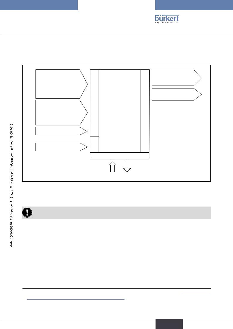
9.Interfaces of the positioner for the multipole model
Inputs for position or |
|
|
|
2 binary outputs |
|
process set-point value |
|
|
|
||
|
|
|
|
||
4 |
– 20 mA |
|
Positioner |
|
|
0 |
– 20 mA |
|
|
Proximity switch 1 |
|
0 |
– 10 V |
|
(Multipole model) |
|
|
0 |
– 5 V |
|
|
|
|
Input for process |
|
|
Outputs |
Analogue |
|
actual value |
Inputs |
|
position feedback |
||
4 |
– 20 mA |
|
|
||
Frequency |
|
|
|||
|
|
|
|
||
Pt 100 |
|
|
|
|
|
Binary input |
|
|
|
|
|
24 V DC |
Supply |
|
|
|
|
|
|
|
|
|
|
|
|
|
Operation |
|
|
Figure 8: Interfaces for the multipole model
The positioners Type 8692 and Type 8693 are 3-wire devices, i.e. the power (24 V DC) is supplied separately from the set-point value signal.
28
english
Type 8692, 8693
Description of system,
10.Interfaces of the positioner for the models with cable gland
Inputs for position or process set-point value 4 – 20 mA
0 – 20 mA
0 – 10 V
0 – 5 V
Input for process actual value1)
4 – 20 mA Frequency Pt 100
Binary input
24 V DC
|
Positioner |
|
(Cable gland) |
Inputs |
Outputs |
Supply
Operation
2 binary outputs1)
(as an alternative to input for process actual value)
Analogue position feedback
Figure 9: Interfaces for the model with cable gland
The positioners Type 8692 and Type 8693 are 3-wire devices, i.e. the power (24 V DC) is supplied separately from the set-point value signal.
1) Type 8693: The switch can be used to supply power to a connected sensor (description see “18.5.1 Terminal
assignment when selecting the process actual value input”) |
29 |
|
english

Type 8692, 8693
Description of system
11.Technical Data
11.1.Safety positions after failure of the electrical or pneumatic auxiliary power
|
|
Safety positions after failure of the auxiliary |
Actuator system |
Designation |
power |
|
|
|
electrical |
pneumatic |
|
|
|
|
pilot-controlled |
|
|
|
|
control system: |
|
|
single-acting |
down |
down |
|
up |
control function A |
direct-acting |
||
|
||||
down |
|
|
control system: |
|
|
|
not defined |
||
|
|
|
||
|
|
|
pilot-controlled |
|
|
|
|
control system: |
|
|
single-acting |
up |
up |
|
up |
control function B |
direct-acting |
||
|
||||
|
|
|||
down |
|
|
control system: |
|
|
|
|
||
|
|
|
not defined |
|
|
double-acting |
down / up |
|
|
up |
(depending on the con- |
not defined |
||
control function I |
nection of the control |
|||
|
||||
down |
|
cables) |
|
|
|
|
|
Table 7: Safety positions
30
english
Loading...