


Type 8635
SIDE Control Positioner
Operating Instructions

We reserve the right to make technical changes without notice. Technische Änderungen vorbehalten.
Sous réserve de modifications techniques.
© 2003 – 2011 Bürkert Werke GmbH
Operating Instructions 1111/06_EU-EN_00804608 / Original DE

CONTENTS
Operating Instructions for |
|
SIDE Control Positioner Type 8635 |
|
(S/HART, PROFIBUS PA, |
|
HART-Hand Terminal) |
|
GENERAL NOTES |
|
Symbols ....................................................................................................................................................................................................................................................... |
10 |
General safety notes ................................................................................................................................................................................................................. |
10 |
Protection from damage by electrostatic charging ...................................................................................................................... |
11 |
Device-related notes ................................................................................................................................................................................................................ |
11 |
Scope of delivery ........................................................................................................................................................................................................................... |
11 |
Warranty conditions ................................................................................................................................................................................................................... |
12 |
Master code (S/HART) .......................................................................................................................................................................................................... |
12 |
SYSTEM DESCRIPTION (S/HART) |
|
Construction of SIDE Control (S/HART) .................................................................................................................................................... |
14 |
Illustration ............................................................................................................................................................................................................................................ |
14 |
Features ............................................................................................................................................................................................................................................... |
15 |
Functional diagram of the SIDE Control (S/HART) in connection with a control |
|
valve with single-acting diaphragm actuator .......................................................................................................................................... |
16 |
Operation as a positioner (S/HART) ................................................................................................................................................................ |
17 |
Characteristics of the positioner software ................................................................................................................................................ |
18 |
Schematic illustration of position control .................................................................................................................................................... |
19 |
Operation as a process controller (S/HART, option) ................................................................................................................ |
20 |
Characteristics of the process controller software (option) ............................................................................................... |
20 |
Schematic illustration of process control ................................................................................................................................................... |
22 |
|
8635 - 1 |

CONTENTS |
|
Interfaces (S/HART) .................................................................................................................................................................................................................. |
23 |
Technical data of the SIDE Control (S/HART) .................................................................................................................................. |
24 |
Technical data (S/HART) ................................................................................................................................................................................................ |
24 |
Factory settings (S/HART) ........................................................................................................................................................................................... |
26 |
SYSTEM DESCRIPTION (PROFIBUS PA) |
|
Construction of Side Control PA (PROFIBUS PA) ...................................................................................................................... |
28 |
Illustration ............................................................................................................................................................................................................................................ |
28 |
Design features .......................................................................................................................................................................................................................... |
29 |
Options................................................................................................................................................................................................................................................... |
29 |
Functional diagram of SIDE Control (PROFIBUS PA) in connection with a control |
|
valve with single-acting diaphragm actuator .......................................................................................................................................... |
30 |
Operating as a positioner (PROFIBUS PA) ........................................................................................................................................... |
31 |
Characteristics of the positioner software ................................................................................................................................................ |
32 |
Schematic illustration of position control .................................................................................................................................................... |
33 |
Interfaces (PROFIBUS PA) ............................................................................................................................................................................................. |
34 |
Technical data of SIDE Control (PROFIBUS PA) ......................................................................................................................... |
35 |
Technical data (PROFIBUS PA) ........................................................................................................................................................................... |
35 |
Factory settings (PROFIBUS PA) ...................................................................................................................................................................... |
36 |
INSTALLATION |
|
Attachment and assembly ................................................................................................................................................................................................ |
38 |
Complete system with Bürkert continuous valve from series 27xx ........................................................................ |
38 |
Attachment to a continuous valve with linear actuator acc. to NAMUR ........................................................... |
39 |
Attachment to a continuous valve with part-turn actuator .................................................................................................... |
42 |
Fluidic connection ........................................................................................................................................................................................................................ |
44 |
Electrical connection (S/HART) .............................................................................................................................................................................. |
45 |
Electrical connection (PROFIBUS PA) ......................................................................................................................................................... |
46 |
2 - 8635

CONTENTS
INDUCTIVE PROXIMITY SWITCHES (S/HART, PROFIBUS PA, OPTION)
Description of the inductive proximity switches ............................................................................................................................... |
48 |
Configuration of the adjusting wheels (option) ................................................................................................................................. |
48 |
Settings ......................................................................................................................................................................................................................................................... |
49 |
Setting with one inductive proximity switch ............................................................................................................................................ |
49 |
Setting with two inductive proximity switches ..................................................................................................................................... |
49 |
Definition of the end positions with part-turn actuators ........................................................................................................ |
49 |
OPERATING AND CONTROLLER FUNCTIONS |
|
Operating and display elements ............................................................................................................................................................................. |
52 |
Operating levels .............................................................................................................................................................................................................................. |
52 |
Commissioning and set-up as a positioner ............................................................................................................................................ |
53 |
Procedure for specifying the basic settings ........................................................................................................................................... |
53 |
Main menu for settings on commissioning ............................................................................................................................................... |
55 |
Description of the procedure ...................................................................................................................................................................................... |
55 |
Configuring the supplementary functions ................................................................................................................................................. |
59 |
Keys in the configuration level.................................................................................................................................................................................. |
59 |
Configuration menu ................................................................................................................................................................................................................ |
59 |
Supplementary functions ................................................................................................................................................................................................ |
62 |
Operating the process ............................................................................................................................................................................................................ |
85 |
Changing between operating modes ............................................................................................................................................................... |
85 |
Operating mode AUTOMATIC (S/HART) .................................................................................................................................................. |
86 |
Meaning of the keys in the operating mode AUTOMATIC .................................................................................................... |
86 |
Displays in the operating mode AUTOMATIC ...................................................................................................................................... |
86 |
Operating mode AUTOMATIC (PROFIBUS PA) ............................................................................................................................. |
87 |
Meaning of the keys in the operating mode AUTOMATIC .................................................................................................. |
87 |
Displays in the operating mode AUTOMATIC ...................................................................................................................................... |
87 |
Operating mode MANUAL ............................................................................................................................................................................................... |
88 |
Meaning of the keys in the operating mode MANUAL ............................................................................................................. |
88 |
Displays in the operating mode MANUAL ................................................................................................................................................ |
88 |
|
8635 - 3 |

CONTENTS |
|
OPERATING THE PROCESS CONTROLLER (S/HART) |
|
Factory settings of the process controller .................................................................................................................................................. |
90 |
Setting up a process control system ................................................................................................................................................................. |
90 |
Self-parametrization for controllers - X.TUNE ................................................................................................................................... |
91 |
Supplementary function P.CONTRL ................................................................................................................................................................. |
91 |
Basic settings of the function P.CONTRL ................................................................................................................................................. |
92 |
P.Q’LIN - starting the routine for linearization of the process characteristic .......................................... |
99 |
Displays during call-up and execution of the routine .................................................................................................................. |
99 |
P.CO TUNE - self-optimization of the process controller (process tune) ................................................ |
100 |
Operation ......................................................................................................................................................................................................................................... |
101 |
Operating the process ........................................................................................................................................................................................................ |
104 |
Changing between operating modes ........................................................................................................................................................... |
104 |
Operating mode AUTOMATIC ................................................................................................................................................................................ |
105 |
Meaning of the keys in operating mode AUTOMATIC ........................................................................................................... |
105 |
Displays in operating mode AUTOMATIC ............................................................................................................................................. |
105 |
Manual changing of the process setpoint ............................................................................................................................................. |
106 |
Operating mode MANUAL ........................................................................................................................................................................................... |
107 |
Meaning of the keys in operating mode MANUAL .................................................................................................................... |
107 |
Displays in operating mode MANUAL ........................................................................................................................................................ |
107 |
CONFIGURATION FOR BUS COMMUNICATION (PROFIBUS PA) |
|
GSD file .................................................................................................................................................................................................................................................... |
110 |
Setting the device address .......................................................................................................................................................................................... |
113 |
Cyclic parameters ............................................................................................................................................................................................................... |
113 |
Configuration parameters ........................................................................................................................................................................................... |
114 |
4 - 8635
|
CONTENTS |
OPERATING VIA THE HART HAND TERMINAL (HART) |
|
General ..................................................................................................................................................................................................................................................... |
120 |
System description .................................................................................................................................................................................................................. |
121 |
Illustration of the system ............................................................................................................................................................................................. |
121 |
Menu description and key assignment ..................................................................................................................................................... |
121 |
Data entry ....................................................................................................................................................................................................................................... |
122 |
Commissioning ............................................................................................................................................................................................................................. |
123 |
Preparation .................................................................................................................................................................................................................................... |
123 |
AUTOTUNE procedure (required on first commissioning) ............................................................................................ |
123 |
Operating the positioners via the HART hand terminal ................................................................................................... |
125 |
Configuration .............................................................................................................................................................................................................................. |
125 |
Display of the process variables ...................................................................................................................................................................... |
125 |
Changing the process variables ........................................................................................................................................................................ |
126 |
Operating the process controller via the HART hand terminal ............................................................................. |
127 |
Configuration .............................................................................................................................................................................................................................. |
127 |
Display of the process variables ...................................................................................................................................................................... |
130 |
Changing the process variables ........................................................................................................................................................................ |
130 |
Memory organization ........................................................................................................................................................................................................... |
132 |
MAINTENANCE AND ERROR ELIMINATION ON THE POSITIONER |
|
Maintenance ...................................................................................................................................................................................................................................... |
134 |
Error messages and malfunctions .................................................................................................................................................................... |
134 |
Error messages on the LC display ................................................................................................................................................................ |
134 |
Other malfunctions ............................................................................................................................................................................................................. |
135 |
MAINTENANCE AND ERROR ELIMINATION ON THE PROCESS |
|
CONTROLLER (S/HART) |
|
Maintenance ...................................................................................................................................................................................................................................... |
138 |
Error messages and malfunctions .................................................................................................................................................................... |
138 |
Error messages on the LC display ................................................................................................................................................................ |
138 |
Other malfunctions ............................................................................................................................................................................................................. |
139 |
|
8635 - 5 |

CONTENTS |
|
Appendix |
|
GENERAL RULES |
|
Selection criteria for continuous valves .................................................................................................................................................... |
142 |
Characteristics of PID controllers ....................................................................................................................................................................... |
144 |
P fraction .......................................................................................................................................................................................................................................... |
144 |
I fraction ............................................................................................................................................................................................................................................ |
145 |
D fraction ......................................................................................................................................................................................................................................... |
146 |
Superposition of P, I and D fractions ............................................................................................................................................................ |
147 |
Realized PID controller ................................................................................................................................................................................................. |
148 |
Setting rules for PID controllers ............................................................................................................................................................................ |
149 |
Setting rules after Ziegler and Nichols (oscillation method) ........................................................................................... |
149 |
Setting rules after Chien, Hrones and Reswick (output step method) ............................................................. |
150 |
OPERATING STRUCTURE |
|
Operating structure of the SIDE Control (S/HART) ................................................................................................................ |
154 |
Operating structure of the SIDE Control (PROFIBUS PA) ........................................................................................... |
159 |
Operating structure of the HART hand terminal (HART) ............................................................................................... |
160 |
TABLE FOR POSITIONER............................................................................................................................................................................ |
165 |
TABLES FOR PROCESS CONTROLLER (S/HART) ......................................................................... |
167 |
MASTER CODE (S/HART) ............................................................................................................................................................................. |
169 |
6 - 8635

|
CONTENTS |
APPROVALS (S/HART) |
|
Declaration of Conformity for Positioner Type 8635 SIDE Control S/HART .................................... |
174 |
EC Design Inspection Certificate for Positioner Type 8635 SIDE Control S/HART |
............. 175 |
APPROVALS (PROFIBUS PA) |
|
Declaration of Conformity for Positioner Type 8635 SIDE Control PA ....................................................... |
180 |
EC Design Inspection Certificate for Positioner Type 8635 SIDE Control PA ............................... |
181 |
|
|
1st Supplement ....................................................................................................................................................................................................................... |
184 |
APPROVALS (S/HART, PROFIBUS PA) |
|
EC Design Inspection Certificate (ATEX) for slot initiators Types SJ ... and SC ... ................. |
186 |
|
|
Inductive proximity switch NAMUR .............................................................................................................................................................. |
189 |
8635 - 7

CONTENTS
8 - 8635
GENERAL NOTES
GENERALNOTES
Symbols ......................................................................................................................................................................................................................................................... |
10 |
General safety notes ................................................................................................................................................................................................................... |
10 |
Protection from damage by electrostatic charging ........................................................................................................................ |
11 |
Device-related notes .................................................................................................................................................................................................................. |
11 |
Scope of delivery ............................................................................................................................................................................................................................. |
11 |
Warranty conditions ..................................................................................................................................................................................................................... |
12 |
Master code (S/HART) ............................................................................................................................................................................................................ |
12 |
8635 - 9
GENERAL NOTES
Symbols
The following symbols are used in these operating instructions:
marks a work step that you must carry out.
ATTENTION!
marks notes on whose non-observance your health or the functioning of the device will be endangered.
NOTE |
|
marks important additional information, tips and recommendations. |
|
|
|
(S/HART) |
indicate chapters or sections of the text which are valid only for certain versions of the |
|
(PROFIBUS PA) |
SIDE Control. |
|
(HART) |
|
|
General safety notes
Please observe the notes in these operating instructions together with the conditions of use and permitted data that are specified in the data sheets of the electropneumatic positioner, in order that the device will function perfectly and remain operable for a long time:
•This device left the manufacturer's factory in a faultless condition with regard to technical safety and was tested. Proper transport, storage and installation are the prerequisites for continued correct functioning.
•Keep to standard engineering rules in planning the use of and operating the device!
•Installation and intervention for maintenance work are only allowed by qualified personnel using suitable tools!
•Observe the current regulations on accident prevention and safety for electrical devices during operation and maintenance of the device!
•Take suitable precautions to prevent inadvertent operation or damage by unauthorized action!
•On non-observance of these notes and unauthorized interference with the device, we will refuse all liability and the warranty on device and accessories will become void!
10 - 8635

GENERAL NOTES
Protection from damage by electrostatic charging
ATTENTION
EXERCISE CAUTION ON HANDLING!
ELECTROSTATICALLY SENSITIVE
COMPONENTS / MODULES
This device contains electronic components that are sensitive to electrostatic discharge (ESD). Contact to electrostatically charged persons or objects will endanger these components. In the worst case, they will be immediately destroyed or will fail after commissioning.
Observe the requirements of EN 100015-1 (IEC 61340-5-1) in order to minimize the possibility of, or avoid, damage from instantaneous electrostatic discharge. Also take care not to touch components that are under supply voltage.
Device-related notes
•For installation and operation in potentially hazardous (explosive) locations, observe the regulations. These are to be found in EN 60079-14 (IEC 60079-14).
•On electrical connection of the inherently safe circuits, observe the data in the relevant certificate of conformity.
•Take suitable precautions to prevent electrostatic charging of plastic parts of the housing (see EN 100015-1 / IEC 61340-5-1).
•No components shall be connected to the inputs and outputs of the boards whose electrical data lie outside the limits determined for inherently safe operation and stated on the data sheet for the positioner.
•In potentially explosive locations, only inherently safe devices (of EN 50020 / IEC 60079-11) shall be connected to the serial interface.
•The plastic covering shall be removed only by the manufacturer!
•Interventions in the device with the housing open shall not be carried out in very humid or aggressive atmospheres. Take precautions to prevent inadvertent mechanical damage to the boards or their components. Limit the duration of opening of the housing to that which is absolutely necessary.
Scope of delivery
Immediately after receipt of a shipment, make sure that the contents are undamaged and match the scope of delivery stated on the packing slip. In general this consists of:
•SIDE Control
•Operating Instructions for the SIDE Control
Add-on kits for linear and part-turn actuators may be obtained as accessories.
If there are discrepancies, please contact immediately our customer service:
Bürkert Fluid Control System
Bürkert Fluid Control Systems / Service Department
Sales Center
Christian.-Bürkert-Bürkert-Str.-13Str-.1713-17
D-746536453 IngelfingenIngelfingen
TTell..: (+49+ 497940)(0) 794010-111- 10 Fax:91 111(+49 7940) 10-448
Fax + 49 (0) 7940 - 10 91 448
E-Mail: info@de.buerkert.com
E-mail: info@de.buerkert.com
8635 - 11
GENERAL NOTES
Warranty conditions
Warranty
This document contains no SURPLVH RI JXDUDQWHH . 3OHDVH refer to our general WHUPV RIsales andGHOLYHU\.
The warranty is only valid if the device is used as intended in accordance with the specified application conditions.
The warranty is only valid if the device is used as authorized in accordance with the specified application conditions.
ATTENTION! The warranty covers only faultless condition of the SIDE Control. No liability will be accepted for consequential damage of any kind that may arise from failure or malfunctioning of the device.
Mastercode (S/HART)
Operation of the SIDE Control (S/HART) can be blocked with a freely selectable user code. Independent of this, there exists an unchangeable master code with which you can execute all operative actions on the device. This 4-digit master code is to be found in the Appendix of these operating instructions in the
Chapter Master code (S/HART).
If required, cut out this code and keep it separate from these operating instructions.
12 - 8635

SYSTEM DESCRIPTION (S/HART)
SYSTEMDESCRIPTION (S/HART)
Construction of SIDE Control (S/HART) ...................................................................................................................................................... |
14 |
Illustration .............................................................................................................................................................................................................................................. |
14 |
Features .................................................................................................................................................................................................................................................. |
15 |
Functional diagram of the SIDE Control (S/HART) in connection with a control |
|
valve with single-acting diaphragm actuator ............................................................................................................................................ |
16 |
Operation as a positioner (S/HART)................................................................................................................................................................... |
17 |
Characteristics of the positioner software ................................................................................................................................................... |
18 |
Schematic illustration of position control ....................................................................................................................................................... |
19 |
Operation as a process controller (S/HART, option) ................................................................................................................ |
20 |
Characteristics of the process controller software (option) .................................................................................................. |
20 |
Schematic illustration of process control ..................................................................................................................................................... |
22 |
Interfaces (S/HART) .................................................................................................................................................................................................................. |
23 |
Technical data of the SIDE Control (S/HART) ................................................................................................................................... |
24 |
Technical data (S/HART) .................................................................................................................................................................................................. |
24 |
Factory settings (S/HART) .............................................................................................................................................................................................. |
26 |
8635 - 13
SYSTEM DESCRIPTION (S/HART)
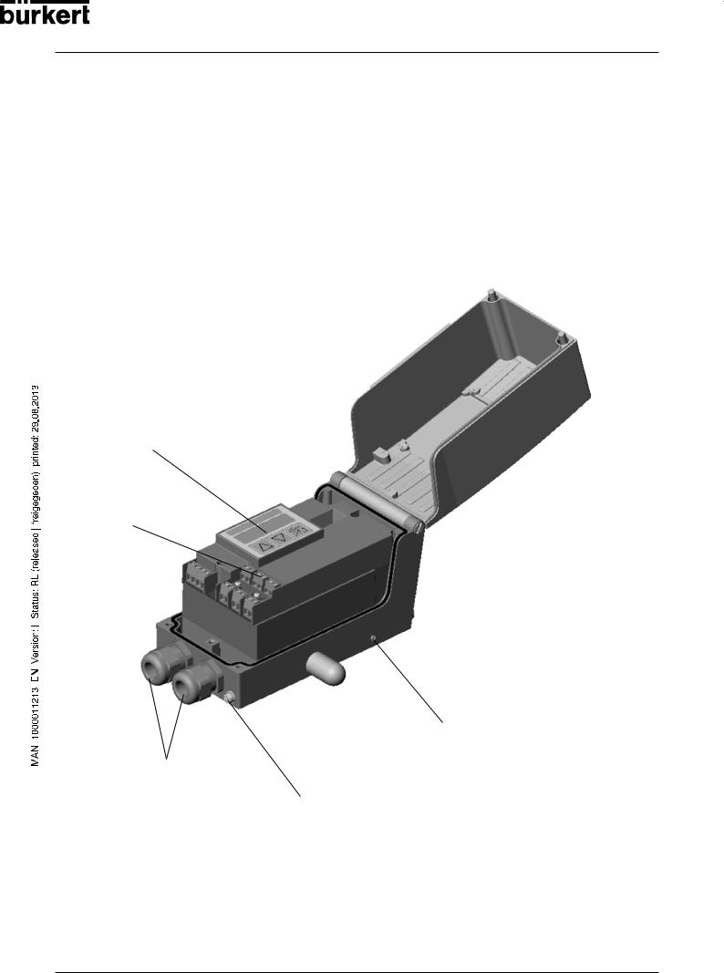
Construction of SIDE Control (S/HART)
The SIDE Control (S/HART) is a digital positioner for pneumatically operated continuous valves with single-acting linear or part-turn actuators.
The SIDE Control (S/HART) can be operated via a keypad with display. An optional extra is communication to the HART protocol.
Illustration
Display with 3 operating keys
Screw terminals
Throttle screw
Bushings M20x1.5
Earthing (grounding) screw
14 - 8635

SYSTEM DESCRIPTION (S/HART)
Features
• Position sensor
Very high resolution conductive plastic potentiometer
• Microprocessor controlled electronics
for signal processing, control and driving the piezoelectric positioning system; setpoint entry and power supply are via a 4 ... 20 mA standard signal.
• Operating elements
The device can be set (configuration and parametrization) locally via three inside keys. An inside, 8- digit, 16-segment LC display is provided, which can also show the setpoint or actual value.
• Positioning system
A piezoelectric positioning system serves to drive the valve actuator.
• Position repeater (option)
via 2 inductive proximity switches (initiators)
• Electrical interfaces
Cable bushing (M20x1.5) with screw terminals
•Pneumatic interfaces
G1/4’’ interior thread
•Housing
Aluminium housing (hard anodized and plastic-coated) with swing-up cover and captive screws.
• Attachment
to linear actuators to NAMUR recommendation (DIN IEC 534 T6) or to part-turn actuators to VDI/VDE 3845.
Option: integral attachment to Bürkert continuous valves
8635 - 15
SYSTEM DESCRIPTION (S/HART)
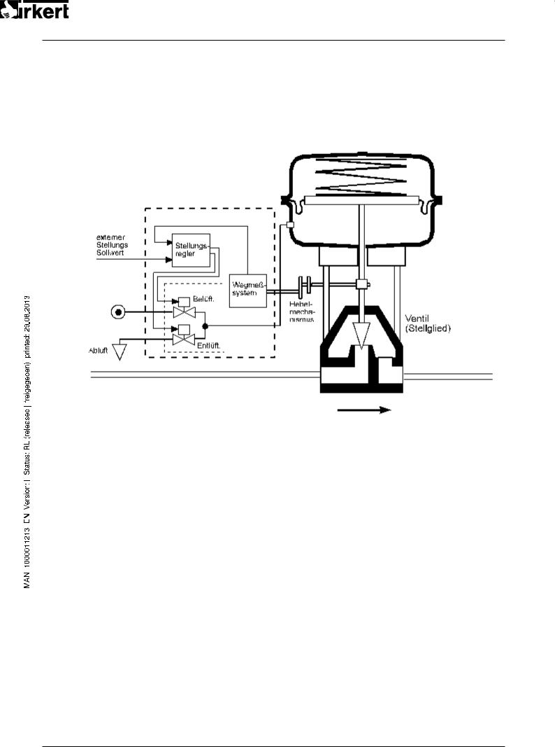
Functional diagram of the SIDE Control (S/HART) connected to a control valve with single-acting diaphragm actuator
SIDE Control
(S/HART)
Actual position
|
External |
|
|
|
|
|
|
|
|
|
|
|
|
|
|
|
|
||
|
|
|
|
|
|
|
|
|
|
|
|
|
|
|
|
|
|||
|
position |
|
|
|
Positioner |
|
|
|
|
|
|
|
|
|
|
||||
|
setpoint |
|
|
|
|
|
|
|
|
|
|
|
Pneumatic actuator |
||||||
|
|
|
|
|
|
|
|
|
|
|
|
|
|
|
|||||
|
|
|
|
|
|
|
|
|
|
|
|
|
|
|
|
|
|
||
|
|
|
|
|
|
|
|
|
|
|
|
|
|
|
|
|
(single-acting) |
||
|
|
|
|
|
|
|
|
|
|
|
|
|
|
|
|
|
|
|
|
|
|
|
|
|
|
Positioning system |
Position |
|
|
|
|
|
|
||||||
|
|
|
|
|
|
sensor |
|
|
|
|
|
|
|||||||
|
|
|
|
|
|
|
|
|
|
|
|
|
|
|
|
|
|
|
|
|
|
|
|
|
|
|
|
pressurize |
|
|
|
|
|
|
|
|
|
||
|
|
|
|
|
|
|
|
|
|
|
|
Lever |
|
|
|
|
|||
|
|
|
|
|
|
|
|
|
|
|
|
|
|
|
|
|
|
|
|
|
|
|
|
|
|
|
|
|
|
|
|
|
|
|
|
|
|
|
|
|
Pressure |
|
|
|
|
|
|
|
|
|
|
|
|
mechanism |
|
Valve (actuator) |
|
||
|
|
|
|
|
|
|
|
|
|
|
|
|
|
|
|||||
|
supply |
|
|
|
|
|
|
|
|
|
|
|
|
|
|
||||
|
|
|
|
|
|
|
|
|
|
|
|
|
|
|
|
|
|
|
|
|
|
|
|
|
|
|
|
|
exhaust |
|
|
|
|
|
|
|
|||
|
|
|
|
|
|
|
|
|
|
|
|
||||||||
|
|
|
|
|
|
|
|
|
|
|
|
|
|
|
|
|
|
|
|
|
Exhaust air |
|
|
|
|
|
|
|
|
|
|
|
|
|
|
|
|||
NOTE |
|
In the case of integral attachment of the SIDE Control (S/HART) to a Bürkert |
|
|
continuous valve, the position sensor is situated outside the SIDE Control (S/HART) |
|
|
on the actuator and is connected to the latter with a cable. |
16 - 8635

SYSTEM DESCRIPTION (S/HART)
Operation as a positioner (S/HART)
The SIDE Control (S/HART controls the position of the pneumatic actuator, whereby the position sensor measures the actual position (POS) of the actuator. The controller compares this actual value of the position with the setpoint (CMD), which is presented as a standard signal. If a control difference (Xd1) exists, a pulse-width modulated voltage signal is sent to the positioning system as the correcting variable. If the difference is positive, the pressurizing piezoelectric valve is driven via output B1; if it is negative, the exhausting piezoelectric valve is driven via output E1. In this way, the position of the actuator is altered until the control difference is 0. Z1 represents a disturbance.
|
|
|
Valve |
opening |
Position |
Positioner |
Positioning system |
Continuous |
|
|
(piezoelectric valves) valve |
|
||
setpoint |
|
|
||
|
|
|
|
|
|
Position control loop |
Position sensor |
|
|
|
|
|
|
|
8635 - 17
SYSTEM DESCRIPTION (S/HART)
Characteristics of the positioner software
|
Supplementary function |
Effect |
|
|
|
|
|
|
Positioner with supplementary functions |
|
|
|
|
|
|
|
AUTOTUNE |
Automatic adaptation of positioner to the control valve |
|
|
in use. |
|
|
|
|
|
|
|
|
|
|
|
|
Valve closes tight outside the control range. A value is |
|
|
Tight-closing function |
specified (in %) from which the actuator is completely |
|
|
|
exhausted (at 0%) or pressurized (at 100%). |
|
|
|
|
|
|
Stroke limitation |
Mech. valve piston movement only within a defined |
|
|
stroke range. |
|
|
|
|
|
|
|
|
|
|
|
Limitation of correcting speed |
Actuator takes a preset time to move from OPEN to |
|
|
CLOSED or from CLOSED to OPEN. |
|
|
|
|
|
|
|
|
|
|
|
Signal range splitting |
Splitting of the standard signal range over 2 or more |
|
|
SIDE Controls. |
|
|
|
|
|
|
|
|
|
|
|
Correction charakteristic for |
Linearization of the process curve can be carried out. |
|
|
adaptation to the operating curve |
|
|
|
|
|
|
|
|
|
|
|
Insensitivity range |
The positioner responds only above a control difference |
|
|
to be specified. |
|
|
|
|
|
|
|
|
|
|
|
Direction of action of the controller |
Reserve of direction of action of the setpoint. |
|
|
setpoint |
|
|
|
|
|
|
|
|
|
|
|
Direction of action of the actuator |
Reserve of direction of action of the actuator. |
|
|
|
|
|
|
Safety position |
Valve moves to a defined safety position |
|
|
|
|
|
|
Code protection |
Blocking of the keypad or menu |
|
|
|
|
|
|
Factory reset |
Reset to factory settings |
|
|
|
|
|
|
Repeater (option) |
|
|
|
|
|
|
|
Analog feedback of position |
Feedback of the values POS and CMD |
|
|
|
|
|
|
Binary outputs |
Feedback of various controller conditions (e.g. sensor |
|
|
breakage or controller in safety position). |
|
|
|
|
|
|
|
|
|
|
|
|
|
|
|
Hierarchic operating concept for simple operation with the following levels |
|
|
|
|
|
|
|
Process operation |
In this level, you switch between Automatic and Manual |
|
|
operation. |
|
|
|
|
|
|
|
|
|
|
|
|
In this level, you specify on commissioning certain |
|
|
Configuration |
basic functions and configure supplementary functions |
|
|
|
as required. |
|
|
|
|
|
|
|
|
|
|
Communication via HART protocol (option) |
|
|
|
|
|
|
|
HART Hand Terminal |
Operation of the SIDE Control via a HART Hand Terminal |
|
|
|
|
|
|
|
|
|
18 - 8635
Schematic illustration of position control
SYSTEM DESCRIPTION (S/HART)
INP
CMD
POS
|
X.CONTRL |
DBDx |
|
POS |
CMD |
|
X.LIMIT |
X.TIME |
|
DIR.ACT |
CUTOFF |
|
|
CHARACT |
|
|
SPLTRNG |
4…20mA |
INP |
DIR.CMD |
8635 - 19

SYSTEM DESCRIPTION (S/HART)
Operation as a process controller (S/HART, option)
If the SIDE Control (S/HART) is operated as a process controller, the abovementioned position control becomes a lower-ranking auxiliary control loop. The overall result is a cascade control system.
The process controller (as a main control loop) is implemented in the SIDE Control (S/HART as a PID controller. In this case the process setpoint (SP) is preset and compared with the actual value (PV) of the process variable to be controlled, which is supplied by a sensor. Formation of the correcting variable is done according to the description of the positioner. Z2 represents a disturbance acting on the process.
Characteristic of the process controller software (option)
Supplementary function |
Effect |
|
|
|
|
Positioner with supplementary functions |
||
|
|
|
AUTOTUNE |
Automatic adaptation of positioner to the control valve |
|
in use. |
||
|
||
|
|
|
|
Valve closes tight outside the control range. A value is |
|
Tight-closing function |
specified (in %) from which the actuator is completely |
|
|
exhausted (at 0 %) or pressurized (at 100 %) . |
|
|
|
|
Stroke limitation |
Mech. valve piston movement only within a defined |
|
stroke range. |
||
|
||
|
|
|
Limitation of correction speed |
Actuator takes a preset time to move from OPEN to |
|
CLOSED or from CLOSED to OPEN. |
||
|
||
|
|
|
Correction characteristic for |
Linearization of the process curve can be carried out. |
|
adaptation to the operating curve |
||
|
||
|
|
|
Insensitivity range |
The positioner responds only above a control difference |
|
to be specified. |
||
|
||
|
|
|
Direction of action of the controller |
Reverse of direction of action of the setpoint. |
|
setpoint |
||
|
||
|
|
|
Direction of action of the actuator |
Reverse of direction of action of the actuator. |
|
|
|
|
Safety position |
Valve moves to a defined safety position |
|
|
|
|
Code protection |
Blocking of the keypad or menu |
|
|
|
|
Factory reset |
Reset to factory settings |
|
|
|
|
20 - 8635

SYSTEM DESCRIPTION (S/HART)
Supplementary function |
Effect |
|
|
|
|
Connectable process controller with the following characteristics (option) |
||
|
|
|
Control structure |
PID |
|
|
|
|
Parameters which can be set |
Proportional action factor, reset time, rate time and |
|
operating point |
||
|
||
|
|
|
Scalable inputs |
Position of decimal points, lower and upper scale |
|
values of process value and setpoint |
||
|
||
|
|
|
Selection of setpoint specification |
Setpoint specified either via standard signal input or via |
|
keys |
||
|
||
|
|
|
|
|
|
Hierarchic operating concept for simple operation with the following levels |
||
|
|
|
Process operation |
In this level, you switch between Automatic and Manual |
|
operation. |
||
|
||
|
|
|
|
In this level, you specify on commissioning certain |
|
Configuration |
basic functions and configure supplementary functions |
|
|
as required. |
|
|
|
|
8635 - 21

SYSTEM DESCRIPTION (S/HART)
Schematic illustration of process control
22 - 8635
POS CMD |
PV SP |
|
X.CONTRL |
DBDx |
|
POS |
X.LIMIT |
CMD |
X.TIME |
|
DIR.ACT |
|
CUTOFF |
|
|
|
SPLTRNGCHARACT |
|
|
|
DIR.CMD |
Q
SCAL |
P.COFILT |
4…20mA |
SCAL |
|
P.CO |
PV |
|
P.CO |
SP |
|
PV |
SP |
|
|
|
P.CONTRL |
DBDp |
PARA |
INP TUNE |
SYSTEM DESCRIPTION (S/HART)
Interfaces (S/HART)
Note: Optional inputs and outputs are enclosed by dotted lines.
NOTE |
|
The SIDE Control (S/HART) is a 2-conductor device, i.e. the voltage supply is provided via |
|
|
the 4 ... 20 mA signal. |
|
|
|
8635 - 23

SYSTEM DESCRIPTION (S/HART)
Technical data of the SIDE Control (S/HART)
Technical data (S/HART)
OPERATING CONDITIONS |
|
Permissible ambient temperature |
-25 ... +65 °C (with non-Ex devices or T4/T5) |
|
-25 ... +60 °C (with T6) |
System of protection |
IP 65 to EN 60529 |
|
(only with correctly connected cable) |
CONFORMITYTOTHEFOLLOWINGSTANDARDS |
|
CE Symbol |
Conformity wrt. EMC Guideline 89/336/EEC |
Low Voltage Guidline |
73/23/EEC |
Explosion protection (optional) |
EEX ia IIC T4/T5/T6 |
MECHANICALDATA |
|
Housing dimensions, outside (WxHxD) |
174 x 88 x 93 mm |
Housing material |
Aluminium |
|
hard anodized and plastic-coated |
Seal material |
NBR / Neoprene |
Other exterior parts |
stainless steel (V4A) |
Mass |
approx. 1.5 kg |
ELECTRICALDATA |
|
Connections |
2 M20x1.5 bushings |
|
with screw terminals 0.14 ... 1.5 mm2 |
Power supply |
via setpoint input 4-20 mA |
Burden voltage |
< 12 V DC |
Burden resistance |
590 Ω at 20 mA and 11.8 V DC |
Process value input (option) |
4-20 mA |
Burden voltage |
200 mV at 20 mA |
Burden resistance |
10 Ω |
Binary input |
mechanical make/break contact |
Inductive proximity switch (optional) |
to DIN EN 60947-5-6 (NAMUR) |
Structural shape |
SJ3.5-G-N |
Manufacturer |
Pepperl+Fuchs |
Output signal for |
|
switching amplifier |
to DIN EN 50227 (NAMUR) |
Rated voltage U0 |
8 V |
Current (sensor uncoated) |
≥ 2.1 mA |
Current (sensor coated) |
≤ 1.2 mA |
24 - 8635

SYSTEM DESCRIPTION (S/HART)
Analog repeat (optional)
Supply voltage
Burden
Binary outputs (optional)
Supply voltage
Current in switching status OPEN Current in switch. status CLOSE Sense of action
max. permissible values
PNEUMATIC DATA
Control medium
Dust content
Water content
Oil content Temperatur range of compressed air
Pressure range Supply pressure variation
Air flow capacity of control valve at 1.4 bar pressure drop over valve
at 6 bar pressure drop over valve
Self-consumption of air in balanced state Throttle screw Connections
4 ... 20 mA (electrically isolated)
Usupply = 12 ... 30 V DC
Usupply ≥ 12 V + RB • 20 mA
to EN 50 227 (electrically isolated) 5 ... 11 V DC
<1.2 mA
>2.1 mA
NO (normally open) or NC (normally closed) (may be parametrized)
see Declaration of Conformity
Quality classes to DIN ISO 8573-1
Class 5:
max. 40 µm particle size
max. 10 mg/m³ particle density Class 3:
max. pressure dew point
-20 °C or at least 10 degrees below lowest operating temperature
Class 3: max. 1 mg/m³
-25 ... + 65 °C (with non-Ex devices or T4/T5)
-25 ... + 60 °C (with T6)
1.4... 6.0 bar
max. ± 10 % during operation
ca. 55 LN/min STP for pressurizing and exhausting
ca. 170 LN/min STP for pressurizing and exhausting
0.0 LN/min STP adjustment ratio ca.10:1 G1/4'' internal thread
8635 - 25
SYSTEM DESCRIPTION (S/HART)
Factory settings (S/HART)
Function |
Factory setting |
|
Function |
Factory setting |
|||||||
|
|
|
|
|
|
|
|
|
|
||
CHARACT |
CHA LIN |
|
X.CONTRL |
|
|
|
|
|
|
||
CUTOFF |
CUT |
= 0 %; CUT |
= 100 % |
X.CO DBND |
1 % |
|
|
||||
|
|
|
|
|
|
|
|||||
DIR.CMD |
DIR.CRISE |
|
X.CO PARA |
|
|
|
|
|
|
||
|
KX |
Values determined by AUTOTUNE |
|||||||||
DIR.ACT |
DIR.ARISE |
|
|||||||||
|
KX |
Values determined by AUTOTUNE |
|||||||||
SPLTRNG |
SR |
= 0 (%); SR |
= 100 (%) |
||||||||
After execution of SETFACT: 1 |
|||||||||||
X.LIMIT |
LIM |
= 0 %, LIM |
= 100 % |
||||||||
P.CONTRL |
|
|
|
|
|
|
|||||
|
|
|
|
|
|
|
|
|
|
||
X.TIME |
|
|
|
P.CO DBND |
1 % |
|
|
||||
T.OPN |
Values determined by AUTOTUNE |
P.CO PARA |
|
|
|
|
|
|
|||
T.CLS |
Values determined by AUTOTUNE |
KP |
1.00 |
|
|
||||||
TN |
999.9 |
|
|
||||||||
After execution of SETFACT: 1 s |
|
|
|
||||||||
|
TV |
0.0 |
|
|
|
|
|||||
|
|
|
|
|
|
|
|
||||
OUTPUT |
|
|
|
X0 |
0 |
|
|
|
|
|
|
OUT ANL: |
|
|
|
P.CO SETP |
SETP INT |
||||||
OUT POS |
OUT 4'20 A |
|
P.CO FILT |
0 |
|
|
|
|
|
||
OUT BIN: |
|
|
|
P.CO SCAL |
PV |
|
|
000.0, PV |
|
100.0 |
|
|
|
|
|
|
|
||||||
|
|
|
|
|
|
||||||
OUT DEV |
DEV 5.0 NORM OPN |
P.CO TUNE |
D’ACT |
||||||||
SAFEPOS |
0 |
|
|
CODE |
CODE 0000 |
||||||
BIN-IN |
B.IN SPOS / NORM OPN |
|
|
|
|
|
|
|
|||
|
|
|
|
|
|
|
|
|
|
|
|
|
|
|
|
|
|
|
|
|
|
|
|
NOTE |
|
The functions and factory settings shown in grey are optionally valid with |
|
|
analog repeat (OUTPUT) or with process controller (P.CONTRL). |
|
|
26 - 8635

SYSTEM DESCRIPTION (PROFIBUS PA)
SYSTEMDESCRIPTION
(PROFIBUS PA)
Construction of SIDE Control (PROFIBUS PA) ............................................................................................................................... |
28 |
Illustration ............................................................................................................................................................................................................................................. |
28 |
Features ................................................................................................................................................................................................................................................. |
29 |
Options .................................................................................................................................................................................................................................................... |
29 |
Functional diagram of the SIDE Control (PROFIBUS PA) in connection with a |
|
control valve with single-acting diaphragm actuator ..................................................................................................................... |
30 |
Operation as a positioner(PROFIBUS PA) ............................................................................................................................................. |
31 |
Characteristics of the positioner software ................................................................................................................................................. |
32 |
Schematic illustration of position control ...................................................................................................................................................... |
33 |
Interfaces (PROFIBUS PA) ............................................................................................................................................................................................. |
34 |
Technical data of the SIDE Control (PROFIBUS PA) ............................................................................................................. |
35 |
Technical data (PROFIBUS PA) ............................................................................................................................................................................. |
35 |
Factory settings (PROFIBUS PA) ........................................................................................................................................................................ |
36 |
8635 - 27

SYSTEM DESCRIPTION (PROFIBUS PA)
Construction of SIDE Control (PROFIBUS PA)
The SIDE Control (PROFIBUS PA) is a digital positioner for pneumatically operated continuous valves with single-acting linear or part-turn actuators.
The SIDE Control (PROFIBUS PA) can be controlled via PROFIBUS PA from a central automation system (e.g. process control system). The momentary valve position is reported via the bus.
For detailled information on commissioning a PROFIBUS PA branch, we recommend the PROFIBUS Commissioning Guidelines by the PROFIBUS Users Organization (PUO).
Illustration
DIP switch (device address)
Display with 3 operating keys
Screw terminal
Clamping screw (for attaching the bus screen)
Throttle screw
Bushings
M20 x 1.5 Earthing
(grounding) screw
28 - 8635
 Loading...