


 PTB 03 ATEX 5014 X
 Type 0641 / 2832 / 6013 / 6022
 Solenoid valve for use in the gas feedback systems
 for petrol pumps
 Magnetventile zum Einsatz in
 Gasrückführungssystemen von Tanksäulen
 Electrovannes pour emploi dans systèmes
  recyclage de gaz de distributeurs de
Example
Beispiel
Exemple
Type 0641
Operating Instructions
Bedienungsanleitung Manuel d‘utilisation

We reserve the right to make technical changes without notice. Technische Änderungen vorbehalten.
Sous réserve de modifications techniques.
© 2003 - 2011 Bürkert Werke GmbH
Operating Instructions 1107/07_EU-ML_00804694 / Original DE

Solenoid valves approved for use in the gas feedback systems of petrol pumps
Magnetventile mit Zulassung für den Einsatz in Gasrückführungssystemen von Tanksäulen
Electrovannes avec homologation pour emploi dans des systèmes de recyclage des gaz de distributeurs de carburant
Valve |
with cast-on cable |
with terminal box |
Ventil |
mit eingegossener Leitung |
mit Klemmkasten |
Vanne |
avec câble de raccordement |
avec boîte à bornes |
|
|
|
Type |
|
|
0641 |
|
|
|
|
|
Type |
|
|
2832 |
|
|
|
|
|
|
|
|
03 ATEX5014 X - 3

Valve |
with cast-on cable |
with terminal box |
Ventil |
mit eingegossener Leitung |
mit Klemmkasten |
Vanne |
avec câble de raccordement |
avec boîte à bornes |
Type |
|
|
6013 |
|
|
Type |
|
|
6022 |
|
|
4 - 03 ATEX5014 X

DEVICES WITH II 1 / 2 G EX M AND / OR
II 1 / 2 G EX EM-APPROVAL
PTB 03 ATEX 5014 X
CONTENT: |
|
||
1 |
GENERAL INFORMATION......................................................................................................... |
6 |
|
|
1.1 |
The operating instructions......................................................................................... |
6 |
|
1.2 |
Symbols......................................................................................................................... |
6 |
|
1.3 |
Correct utilisation........................................................................................................ |
7 |
|
1.4 |
General Safety Instructions....................................................................................... |
8 |
|
1.5 |
General Information.................................................................................................... |
9 |
2 |
APPLICATION CONDITIONS FOR THE UNITS........................................................... |
10 |
|
|
2.1 |
Special conditions..................................................................................................... |
10 |
|
2.2 |
Marking of the units.................................................................................................. |
12 |
3 |
TECHNICAL DATA...................................................................................................................... |
13 |
|
|
3.1 |
Technical data for the type 0641 and 2832 units............................................. |
14 |
|
3.2 |
Technical data for the type 6013 and 6022 units............................................. |
16 |
4 |
INSTALLATION AND COMMISSIONING......................................................................... |
18 |
|
|
4.1 |
Assembly..................................................................................................................... |
19 |
|
4.2 |
Commissioning.......................................................................................................... |
20 |
5 |
MAINTENANCE AND FAULTS.............................................................................................. |
20 |
|
|
5.1 |
Faults............................................................................................................................ |
20 |
6 |
ACCESSORIES............................................................................................................................ |
21 |
|
7 |
PACKING AND TRANSPORT................................................................................................ |
21 |
|
8 |
STORAGE....................................................................................................................................... |
21 |
|
9 |
DISPOSAL...................................................................................................................................... |
21 |
|
english
03 ATEX5014 X - 5
english
1GENERAL INFORMATION
 1.1 The operating instructions
The operating manual describes the whole life cycle of the appliance. Store
this manual in such a way that is easily accessible to every user and is avai-
lable to every new owner of the appliance.
 WARNING!
The operating manual must be read and understood.
• Read the operating manual carefully.
• Pay particular attention to the sections Intended Use and General Safety Precautions!
 1.2 Symbols
The following symbols are used throughout this manual:
 DANGER!
High risk
•Serious or fatal injuries if the safety precautions are not observed.
 WARNING!
Middle risk
•Injuries or serious equipment damage if the safety precautions are not observed.
 CAUTION!
Low risk
• Equipment damage if the safety precautions are not observed.
 NOTES!
 indicates important additional information, tips and recommendations.
NOTES!
refers to information in this operating manual or in other documents.
indicates a work step which you must carry out.
6 - 03 ATEX5014 X

1.3Correct utilisation
The device may only be used for the applications indicated in the chapter Operating conditions for the devices, and only in connection with third-party devices or components recommended or approved by Bürkert. Observe the instructions in this operating manual, as well as the conditions of use and permissible data specified in the chapter Operating conditions for the devices.
The proper and safe function of the system depends on proper transport, storage and installation, and on careful operation and maintenance.
• The solenoid valves may only be used for the control of explosive steam/ gas mixtures of flammable liquids of Explosion Group IIA and Temperature Classes T1 to T3 in accordance with EN 60079-14.
• The solenoid valves may only be set up in petrol pumps between the pump valve and the gas feedback pump. The setting-up of the solenoid valve must be based on EN 60079-14.
• The solenoid valves are to be used in the gas feedback equipment of filing stations, for the control of explosive steam/gas mixtures of flammable liquids of the Danger Classes A I, A II and B, insofar as the liquids belong to Explosion Group IIA and the Temperature Classes T1 to T3 according to EN 60079-14 and the provisions and conditions defined in the Qualification Test Certificate are complied with.
• The protection class used is the Encapsulation Ex m for coils with cable connection or encapsulation with increased safety Ex em for coils with terminal boxes.
• Any other utilisation, or a utilisation going beyond this use will be regarded as improper. Bürkert will accept no liability for any damage resulting from such use. The user must bear all the risk alone.
1.3.1 Approvals of the electromagnets
Valve type |
Electromagnet |
Approval |
|
|
|
|
|
0641 |
64.- |
PTB 02 ATEX 2094X |
|
2832 |
|||
|
|
||
|
|
|
|
6013 |
Typ AC10-..-.-PD47 + |
PTB 00 ATEX 2129X |
|
6022 |
PD53 + PD60 + PD66 |
||
|
|
|
english
03 ATEX5014 X - 7

english
1.4General Safety Instructions
 DANGER!
Risk of explosion if the device is opened!
• The device is a sealed system. It must not be opened.
 DANGER!
Electrical power supply in the system!
Acute risk of injury from hazardous structure-borne voltage!
Risk of damage to the device due to short circuit!
• Work on the electrical system may only be carried out by qualified electricians.
•Before starting work, switch off the power supply and secure to prevent it being switched on again!
•Observe the applicable accident prevention and safety regulations for electrical devices!
 WARNING!
Pressurised system!
Interventions in the pneumatic system represent an acute risk of injury.
•Work on the pneumatic system may only be carried out by qualified and instructed personnel using appropriate tools.
•First switch off pressure before disconnecting lines and valves.
•Observe the flow direction during installation!
•Observe the applicable accident prevention and safety regulations for pneumatic systems!
 WARNING!
General hazards!
Hazards can lead to precarious situations.
•Unintentional operation or impermissible damage can lead to generally dangerous situations including physical injury. Take appropriate measures to prevent unintentional operation or impermissible damage!
•The generally recognised safety engineering rules apply for the planning and operation of the device. These rules must be observed.
NOTES!
The device has been developed in accordance with the acknowledged safety engineering rules and corresponds to the state of the art. However, risks may arise. Operate the device only in a proper and safe state and in accordance with the operating manual.
8 - 03 ATEX5014 X

1.5 General Information
1.5.1 Contact address
Germany
Bürkert Fluid Control Systems
Sales Center
Chr.-Bürkert-Str. 13-17
D-74653 Ingelfingen
Tel. + 49 (0) 7940 - 10 91 111
Fax + 49 (0) 7940 - 10 91 448
E-mail: info@de.buerkert.com
International
Contact addresses can be found on the final pages of the printed operating
instructions.
And also on the Internet under: www.burkert.com
1.5.2Warranty
The warranty is only valid if the device is used as intended in accordance with the specified application conditions.
1.5.3Approvals
The EC Type Examination Certificate PTB 03 ATEX 5014 X has been drawn up by the
PTB (Physikalisch Technische Bundesanstalt) Bundesallee 100
38116 Braunschweig
who also audited the manufacture (CE0102).
1.5.4Information on the Internet
Operating instructions and data sheets for type 0641 (2832/6013/6022) may be found on the Internet under:
www.buerkert.com
english
03 ATEX5014 X - 9
english
2APPLICATION CONDITIONS FOR THE UNITS
 2.1 Special conditions
 2.1.1 Short-circuit protection
As a short-circuit protection, each magnet must be connected in series
with a fuse corresponding to its rated current (max. 3 x Ib according to IEC
60127-2-1) or a motor protector switch with a fast-acting short-circuit and
thermal trip (set to the rated current). For very small rated currents for the
magnets, the fuse with the smallest current value according to the abo-
ve-mentioned IEC standard will suffice. This fuse may be mounted in the
associated supply unit or must be connected in series separately. The rated
voltage of the fuse must be equal to or larger than the quoted nominal vol-
tage of the magnet. The switch-off capability of the fuse cartridge must be
equal to or greater than the maximum theoretical short-circuit current at the
installation location (normally 1500 A).
For the valve types 0641, 2832, 6013 and 6022 in the versions without fuses, the short-circuit protection must be guaranteed by the operator. For the version with a fuse, the latter is built into the terminal box of the device. A more detailed description of the models can be found in the Technical Data section of the various models.
Fuse ...... A
2.1.2Conformity
In accordance with the EC Declaration of conformity, Type 0641, 2832, 6013 and 6022 is compliant with the EC Directives.
2.1.3Standards
Conformity with the EC Directives is verified by the following standards. EN13463-1, EN13617-1
2.1.4Operational temperature range
Please note the operational temperature range listed for each type in the
Electrical Data!
10 - 03 ATEX5014 X
2.1.5 Use in petrol pumps
DANGER!
Risk of explosion if the device is opened!
• The valves may only be dismantled by the manufacturer. The always represent a closed system!
The Type 0641, 2832, 6013 and 6022 solenoid valves (Inner Zone 0) are used for explosive steam/air mixtures in the in gas feedback equipment of filling stations.
Bolted together as a block
Type 0641 and Type 2832
The magnetic coil 64.- is mounted on the body using 4 sealed M4x59 cylinder screws.
The magnetic coil AC10-..-.-... is secured onto the fitting using a sealed nut.
english
03 ATEX5014 X - 11

2.2Marking of the units
english
Two markings are made on the units:
1) Marking of the units with the specific approval of the coil
Approval |
PTB 00 ATEX 2129X |
PTB 02 ATEX 2094X |
|
no. |
|
|
|
|
|
|
|
Protection |
II 2G Ex m II T4, T5, T6 |
II 2G Ex m II T4, T5 |
|
type |
|||
or |
or |
||
|
|||
|
II 2G Ex em II T4, T5, T6 |
II 2G Ex mb e II T4, T5 |
|
|
or |
|
|
|
II 2D Ex tD A21 IP65 |
|
|
|
T -40/-30 °C... |
|
|
|
|
|
2) Marking of the units with the approval of the complete unit for the control of explosive steam/air mixture explosive steam/air mixtures in the gas feedback systems of filling stations
-Approval no.: PTB 03 ATEX 5014 X
-Protection type: II 1/2G Ex m II T3 or II 1/2G Ex em II T3
The composition of the symbol of the protective class is aligned to the protection class of the components used in each case.
Valve |
|
Marking 1 |
Marking 2 |
|
type |
|
(Magnetic coil) |
(Complete unit) |
|
|
|
|||
|
|
|
|
|
0641 |
Approval |
PTB 02 ATEX 2094X |
PTB 03 ATEX 5014X |
|
2832 |
|
|
|
|
Protection |
II 2G Ex m II T4, T5 |
II 1/2G Ex m II T3 |
||
|
||||
|
type |
or |
or |
|
|
|
II 2G Ex mb e II T4, T5 |
II 1/2G Ex em II T3 |
|
|
|
|
|
|
6013 |
Approval |
PTB 00 ATEX 2129X |
PTB 03 ATEX 5014X |
|
6022 |
|
|
|
|
Protection |
II 2G Ex m II T4, T5, T6 |
II 1/2G Ex m II T3 |
||
|
||||
|
type |
or |
or |
|
|
|
II 2G Ex em II T4, T5, T6 |
II 1/2G Ex em II T3 |
|
|
|
or |
|
|
|
|
II 2D Ex tD A21 IP65 |
|
|
|
|
T -40/-30 °C ... |
|
|
|
|
|
|
Ex em with terminal box
Ex m with 3 meters of cable
12 - 03 ATEX5014 X
3TECHNICAL DATA
DANGER!
Risk of explosion!
Exceeding the technical data indicated on the rating plate increases the explosion risk!
Never exceed the technical data indicated on the rating plate!
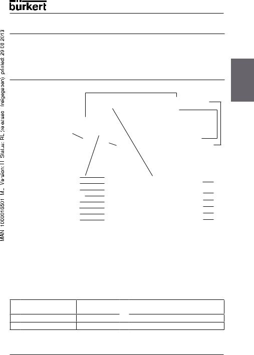
PTB approval number of the magnetic coil
|
|
CE designation |
|
Fuse |
PTB certification No. |
|
|
|
|
... A |
|
Rating plate of the complete unit |
Rating plate of the magnetic coil |
|
english
Orifice - Sealing material - Body material |
Mode of protection / temperature code |
|
Port size for fluid part - Pressure range |
Coil type |
|
Voltage (±10 %) - Power |
|
Voltage (±10 %) - power rating |
variable code - PTB-Approval number |
Serial no. of the coil |
|
Approval - Protection Class - Temperature |
Ident. no / date of production |
|
class |
|
|
Serial no. of the coil /CE designation |
Space for barcode |
|
Ident. no / date of production |
|
|
Space for barcode |
|
|
Valve type |
Code for the marking of units for use in the gas feedback sys- |
|
|
tems of petrol pumps (Coil size) |
|
0641 / 2832 |
|
PD 36 |
6013 / 6022 |
|
PD 97 |
03 ATEX5014 X - 13

3.1Technical data for the type 0641 and 2832 units
english
Temperature class |
T3 |
|
|
|
|
Electromagnet used |
Type 64.-, PTB 02 ATEX 2094X |
|
|
|
|
Circuit function of the valve |
A = normally closed |
|
|
|
|
Type of current |
Universal current (0 Hz ... 60 Hz) |
|
|
|
|
Rated voltage |
12 V ... 240 V (±10 %) |
|
|
|
|
Rated current |
0.58 ...0.034 A |
|
|
|
|
Power limit at steady state |
7 W |
|
|
|
|
Maximal permissible ambient |
Individually mounted -40 °C ... +60 °C |
|
temperature range |
Block assembly -40 °C ... +45 °C |
|
|
|
|
Type of protection |
IP 65 according to EN 60529 |
|
(DIN VDE 0470 Part 1) |
||
|
||
|
|
|
|
For the marking of the electrical connection |
|
Electrical connection |
variants, the letters A, L and K are used |
|
according to the Approval for Electro- |
||
|
||
|
magnets PTB 02 ATEX 2094X |
|
|
(see following description). |
|
|
|
|
Type of protection / Marking |
Electrical connection "A": |
|
II 2G Ex mb II T4, T5 |
||
of the magnetic coil |
Electrical connection "L" and "K": |
|
|
II 2G Ex mb e II T4, T5 |
|
|
(see following description) |
|
|
|
|
Type of protection / Marking |
Electrical connection "A ": |
|
II 1 / 2 G Ex m II T3 |
||
of the complete unit |
Electrical connection "L" and "K": |
|
|
II 1 / 2G Ex em II T3 |
|
|
(see following description) |
|
|
|
14 - 03 ATEX5014 X
3.1.1 Marking of the mounted solenoid valves
The letters A, L and K are used to differentiate between the electrical connection variants for the electromagnets.
Internal code: |
|
|
|
|
|
|||
|
|
|
|
english |
||||
The internal code is used for the marking of the mounted solenoid valves. |
||||||||
|
||||||||
|
|
|
|
|
|
|
|
|
|
Marking |
|
Version |
Internal |
|
|
|
|
|
|
|
|
code |
|
|
|
|
|
|
|
|
|
|
|
|
|
|
A |
|
- Permanently installed rubber hose line of the |
without |
|
|
|
|
|
||||||||
|
|
|
type H05 RN-F3G 0,75 |
data |
|
|
|
|
|
|
|
|
|
|
|
|
|
|
|
|
- Terminal box with M 20 x 1.5 cable gland, |
JA02 |
|
|
|
|
|
|
|
without fuse |
|
|
|
|
|
|
|
|
|
|
|
|
|
|
|
|
|
- Terminal box with threaded nipple M 20 x 1.5, |
JA08 |
|
|
|
|
|
L |
|
without fuse |
|
|
|
|
|
|
|
|
|
|
|
|
||
|
|
- Terminal box with threaded nipple NPT ½, |
JA09 |
|
|
|
||
|
|
|
|
|
|
|||
|
|
|
without fuse |
|
|
|
|
|
|
|
|
|
|
|
|
|
|
|
|
|
- Terminal box with threaded nipple G ½, |
JA10 |
|
|
|
|
|
|
|
without fuse |
|
|
|
|
|
|
|
|
|
|
|
|
|
|
|
|
|
- Terminal box with M 20 x 1.5 cable gland |
JA01 |
|
|
|
|
|
|
|
and fuse |
|
|
|
|
|
|
|
|
|
|
|
|
|
|
|
|
|
- Terminal box with M 20 x 1.5 threaded nipple |
JA05 |
|
|
|
|
|
K |
|
and fuse |
|
|
|
|
|
|
|
|
|
|
|
|
||
|
|
- Terminal box with NPT ½ threaded nipple |
JA06 |
|
|
|
||
|
|
|
|
|
|
|||
|
|
|
and fuse |
|
|
|
|
|
|
|
|
|
|
|
|
|
|
|
|
|
- Terminal box with G ½ threaded nipple |
JA07 |
|
|
|
|
|
|
|
and fuse |
|
|
|
|
|
|
|
|
|
|
|
|
|
|
|
|
|
|
|
|
|||
NOTES! |
|
|
|
|
|
|||
|
Connection types with terminal box |
|
|
|
|
|||
|
Available with / without unit protective fuse. |
|
|
|
|
|||
03 ATEX5014 X - 15
3.2Technical data for the type 6013 and 6022 units
|
|
|
|
|
Temperature class |
T3 |
|
|
|
|
|
|
|
|
|
|
|
|
|
|
|
|
Electromagnet |
Type AC10, PTB 00 ATEX 2129X |
||
|
|
|
|
|
used |
|||
|
|
|
|
|
|
|
|
|
english |
|
|
|
|
|
|
|
|
|
|
|
|
Circuit function of |
A = normally closed |
|
||
|
|
|
|
the valve |
|
|||
|
|
|
|
|
|
|||
|
|
|
|
|
|
|
|
|
|
|
|
|
|
|
|
|
|
|
|
|
|
|
Type of current |
Universal current (0 Hz ... 60 Hz) |
||
|
|
|
|
|
|
|
|
|
|
|
|
|
|
Rated voltage |
12 V ... 400 V (±10 %) |
|
|
|
|
|
|
|
|
|
|
|
|
|
|
|
|
Rated current |
Coil size 5 |
|
Coil size 6 |
|
|
|
|
|
||||
|
|
|
|
|
|
|
|
|
|
|
|
|
|
0,68 ...0,02 A |
|
0,8 ... 0,02 A |
|
|
|
|
|
|
|
|||
|
|
|
|
|
|
|
||
|
|
|
|
|
|
|
|
|
|
|
|
|
|
Power limit at |
Coil size 5 |
|
Coil size 6 |
|
|
|
|
|
steady state |
|
|
|
|
|
|
|
|
7 W |
|
9 W |
|
|
|
|
|
|
|
|
|
|
|
|
|
|
|
Maximal permis- |
Coil size 5 |
|
Coil size 6 |
|
|
|
|
|
sible ambient tem- |
|
|
|
|
|
|
|
|
PD47: -30 °C ... +60 °C |
|
PD53: -30 °C ... +60 °C |
|
|
|
|
|
|
perature range |
PD60: -40 °C ... +60 °C |
|
PD66: -40 °C ... +60 °C |
|
|
|
|
|
Single mounting |
|
||
|
|
|
|
|
|
|
|
|
|
|
|
|
|
|
|
|
|
|
|
|
|
|
Type of protection |
IP 65 according to EN 60529 (DIN VDE 0470 Part 1) |
||
|
|
|
|
|
|
|
||
|
|
|
|
|
Electrical connec- |
Electrical connection variants according to approval |
||
|
|
|
|
|
of the type AC 10 electro-magnets PTB 00 ATEX |
|||
|
|
|
|
|
tion |
2129X (see following description). |
||
|
|
|
|
|
|
|||
|
|
|
|
|
|
|
||
|
|
|
|
|
|
The type of protection changes depending on the |
||
|
|
|
|
|
Type of protection |
electrical connection variants (the components used): |
||
|
|
|
|
|
II 2G Ex m II T4, T5, T6 or |
|
||
|
|
|
|
|
/ Marking of the |
|
||
|
|
|
|
|
II 2G Ex em II T4, T5, T6 or |
|
||
|
|
|
|
|
magnetic coil |
|
||
|
|
|
|
|
II 2D Ex tD A21 IP65 T -40/-30 °C ... |
|||
|
|
|
|
|
|
|||
|
|
|
|
|
|
(see following description). |
|
|
|
|
|
|
|
|
|
||
|
|
|
|
|
Type of protection |
The marking changes depending on the electrical |
||
|
|
|
|
|
connection variants (the components used): |
|||
|
|
|
|
|
/ Marking of the |
|||
|
|
|
|
|
II 1 / 2 G Ex m II T3 or II 1 / 2 G Ex em II T3 |
|||
|
|
|
|
|
complete unit |
|||
|
|
|
|
|
(see following description). |
|
||
|
|
|
|
|
|
|
||
|
|
|
|
|
|
|
|
|
NOTES!
Only individual mounting is permissible for units of the types 6013 and 6022.
16 - 03 ATEX5014 X

3.2.1Identification of the electrical connection variants with terminal box
The variable codes given in the following table are used for the marking of the electrical connection variants.
|
|
|
english |
- |
Terminal box with M 20 x 1.5 cable gland, |
|
|
|
Electrical connection variants |
Variable code |
|
- |
Supply line / cable lin |
dependet on the |
|
line length |
|
||
|
|
|
|
|
without fuse |
JA02 |
|
|
|
|
|
- Terminal box with M 20 x 1.5 threaded nipple, |
JA08 |
|
|
|
without fuse |
|
|
|
|
|
|
- Terminal box with NPT ½ threaded nipple, |
JA09 |
|
|
|
without fuse |
|
|
|
|
|
|
- Terminal box with G ½ threaded nipple, |
JA10 |
|
|
|
without fuse |
|
|
|
|
|
|
- |
Terminal box with M 20 x 1.5 cable gland |
JA01 |
|
|
and fuse |
|
|
|
|
|
|
- Terminal box with M 20 x 1.5 threaded nipple |
JA05 |
|
|
|
and fuse |
|
|
|
|
|
|
- Terminal box with NPT ½ threaded nipple |
JA06 |
|
|
|
and fuse |
|
|
|
|
|
|
- Terminal box with G ½ threaded nipple |
JA07 |
|
|
|
and fuse |
|
|
|
|
|
|
For the connection types with supply lines / cable line, the variable code is dependent on the length of the line.
E.g.: The variable code JW04 corresponds to a line length of 500 mm
NOTES!
Connection types with terminal box
Available with / without unit protective fuse.
03 ATEX5014 X - 17

4INSTALLATION AND COMMISSIONING
english
 DANGER!
Danger of explosion!
• The device is a sealed system. The unit must not be dismantled!
The following safety regulations must be observed:
•
•
•The operator must provide suitable stress relief.
•Wires with an outside diameter of 6 to 13 mm may be used. Observe the maximum thermal loading of the cables or wires to be inserted.
•The inserted break-off seal must be matched to the diameter of the cable or wire.
•The rated cross-section of the cable or wire strands must be at least 0.75 mm² and may not exceed 2.5 mm².
•The screws for fixing the cover of the terminal box must be tightened with a torque of 100 Ncm (±5%).
 DANGER!
High voltage!
Acute risk of injury from hazardous structure-borne voltage! Risk of damage to the device due to short circuit!
•Work on the electrical system may only be carried out by qualified electricians.
•Before starting work, switch off the power supply and secure to prevent it being switched on again!
•Live terminals in the terminal box can cause electric shock, short circuit or explosion. Switch off the power supply before opening the terminal box.
•The connecting cables to the electromagnets must be secure, and be laid so that they are adequately protected from mechanical damage.
•Observe the applicable accident prevention and safety regulations for electrical devices!
18 - 03 ATEX5014 X
 Loading...