


LCIE 07 ATEX 6078 X
Electric rotary actuator type 3004 Elektrischer Drehantrieb Typ 3004 Actionneur électrique type 3004
Device with II 2 GD Ex d IIB T6 approval
Geräte mit II 2 GD Ex d IIB T6 Zulassung
Appareils certifiés II 2 GD Ex d IIB T6
Operating Instructions
Bedienungsanleitung Instructions de Service

We reserve the right to make technical changes without notice. Technische Änderungen vorbehalten.
Sous resérve de modification techniques.
© 2008 - 2011 Bürkert Werke GmbH
Operating Instructions 1111/05_EU-ML_00806090 / Original DE

Type 3004
Explosion-protected electric rotary actuator Type 3004
Contents
1. |
OPERATING INSTRUCTIONS........................................................................................................................................................ |
5 |
|
|
1.1. |
Symbols....................................................................................................................................................................................... |
5 |
2. |
CORRECT USE...................................................................................................................................................................................... |
6 |
|
|
2.1. |
Restrictions................................................................................................................................................................................ |
6 |
3. |
GENERAL SAFETY INSTRUCTIONS.......................................................................................................................................... |
7 |
|
4. |
GENERAL INFORMATION................................................................................................................................................................ |
8 |
|
|
4.1. |
Contact address...................................................................................................................................................................... |
8 |
|
4.2. |
Warranty....................................................................................................................................................................................... |
8 |
|
4.3. Devices that have already been delivered cannot be replaced.................................................................... |
8 |
|
|
4.4. Information on the Internet............................................................................................................................................... |
8 |
|
5. |
SYSTEM DESCRIPTION.................................................................................................................................................................... |
9 |
|
|
5.1. |
Designated Application Area............................................................................................................................................ |
9 |
|
5.2. |
General Description.............................................................................................................................................................. |
9 |
|
5.3. |
Exploded views..................................................................................................................................................................... |
10 |
|
5.4. |
Options...................................................................................................................................................................................... |
12 |
6. |
TECHNICAL DATA............................................................................................................................................................................. |
13 |
|
|
6.1. |
Conformity............................................................................................................................................................................... |
13 |
|
6.2. |
Standards................................................................................................................................................................................ |
13 |
|
6.3. |
Approval................................................................................................................................................................................... |
13 |
|
6.4. |
Operating Conditions........................................................................................................................................................ |
13 |
|
6.5. |
Identification.......................................................................................................................................................................... |
13 |
|
6.6. |
General Technical Data.................................................................................................................................................... |
15 |
7. |
INSTALLATION.................................................................................................................................................................................... |
19 |
|
|
7.1. |
Safety instructions.............................................................................................................................................................. |
19 |
|
7.2. |
Installing the rotary actuator......................................................................................................................................... |
19 |
3
English

Type 3004
8. |
INSTALLATION.................................................................................................................................................................................... |
23 |
|
|
8.1. |
Safety instructions.............................................................................................................................................................. |
23 |
|
8.2. |
Electrical installation.......................................................................................................................................................... |
23 |
|
8.3. |
Control card............................................................................................................................................................................ |
27 |
9. |
OPTION: ROTARY ACTUATORS WITH EMERGENCY CURRENT MODEL........................................................... |
31 |
|
|
9.1. |
Description.............................................................................................................................................................................. |
31 |
|
9.2. |
Technical Data....................................................................................................................................................................... |
31 |
|
9.3. |
Electrical connection of safety block........................................................................................................................ |
32 |
|
9.4. |
Installation of safety block into the actuator drive............................................................................................ |
33 |
10. |
START-UP.............................................................................................................................................................................................. |
34 |
|
|
10.1. Safety instructions.............................................................................................................................................................. |
34 |
|
|
10.2. Procedure................................................................................................................................................................................ |
34 |
|
11. |
OPERATION AND FUNCTION..................................................................................................................................................... |
35 |
|
|
11.1. Safety instructions.............................................................................................................................................................. |
35 |
|
|
11.2. Manual operation................................................................................................................................................................. |
35 |
|
12. |
MAINTENANCE, TROUBLESHOOTING................................................................................................................................. |
36 |
|
|
12.1. Safety instructions.............................................................................................................................................................. |
36 |
|
|
12.2. Maintenance Work.............................................................................................................................................................. |
36 |
|
|
12.3. Malfunctions........................................................................................................................................................................... |
36 |
|
13. |
ACCESSORIES................................................................................................................................................................................... |
38 |
|
14. |
PACKAGING AND TRANSPORT................................................................................................................................................ |
39 |
|
15. |
STORAGE.............................................................................................................................................................................................. |
39 |
|
16. |
DISPOSAL............................................................................................................................................................................................. |
39 |
|
4
English

Type 3004
Operating Instructions
1.OPERATING INSTRUCTIONS
The operating instructions describe the entire life cycle of the device. Keep these instructions in a location which is easily accessible to every user and make these instructions available to every new owner of the device.
 WARNING!
The operating instructions contain important safety information!
Failure to observe these instructions may result in hazardous situations.
• The operating instructions must be read and understood.
1.1.Symbols
 DANGER!
Warns of an immediate danger!
• Failure to observe the warning may result in a fatal or serious injury.
 WARNING!
Warns of a potentially dangerous situation!
• Failure to observe the warning may result in serious injuries or death.
 CAUTION!
Warns of a possible danger!
• Failure to observe the warning may result in moderately serious or minor injuries.
NOTE!
Warns of damage to property!
• Failure to observe the warning may result in damage to the device or the equipment.
 Designates additional significant information, tips and recommendations.
 Refers to information in these operating instructions or in other documentation.
→→designates a procedure which you must carry out.
5
English
Type 3004
Correct Use
2.CORRECT USE
 WARNING!
Incorrect use of the electromotive rotary actuator can be dangerous to people, nearby equipment and the environment.
•The rotary actuator can be used indoors, e.g. to actuate fittings, especially ball valves or shut-off flaps.
•During use observe the permitted data, the operating conditions and conditions of use specified in the contract documents and operating instructions, as described in chapter “5. System Description”.
•The device may be used only in conjunction with third-party devices and components recommended and authorized by Bürkert (e.g. ATEX-approved components).
•Correct transportation, correct storage and installation and careful use and maintenance are essential for reliable and problem-free operation.
•Use the device only as intended.
2.1. Restrictions
If exporting the system/device, observe any existing restrictions.
The electromotive rotary actuator Type 3004 was developed with due consideration given to the accepted safety rules and is state-of-the-art. However, dangers can still arise.
Operate the device only when it is in perfect condition and in accordance with the operating instructions.
6
English

Type 3004
General Safety Instructions
3.GENERAL SAFETY INSTRUCTIONS
These safety instructions do not make allowance for any:
•Contingencies and events which may arise during the installation, operation and maintenance of the devices.
•Local safety regulations; the operator is responsible for observing these regulations, also with reference to the installation personnel.
 DANGER!
Risk of electric shock!
There is a serious risk of injury when reaching into the device.
•Before reaching into the device, always switch off the power supply and safeguard to prevent re-activation!
•Connect several electromotive rotary actuators always with phase separation via a switch.
•Protect the device with a mains-operated fuse.
•Observe applicable accident prevention and safety regulations for electrical equipment!
Danger of explosion!
For specific device designs there is a risk of explosion if the device is opened in the explosion-protected area.
• Follow the safety instructions on the rating plate!
Danger of explosion caused by electrostatic charge!
If there is a sudden discharge from electrostatically charged devices or persons, there is a danger of explosion in the EX area.
•Take appropriate measures to prevent electrostatic charges in the EX area.
•Clean the device surface by wiping it gently with a damp cloth.
General hazardous situations.
To prevent injury, ensure:
•That the system cannot be activated unintentionally.
•Do not put any loads on the housing (e.g. by placing objects on it or standing on it).
•Do not make any external modifications to the device housings. Do not paint the housing parts or screws.
•Do not install the actuator with the cover facing down (head first).
•Installation and repair work may be carried out by authorized technicians only and with the appropriate tools.
•After an interruption in the power supply or pneumatic supply, ensure that the process is restarted in a defined or controlled manner.
•The device may be operated only when in perfect condition and in consideration of the operating instructions.
•The general rules of technology apply to application planning and operation of the device.
7
English

Type 3004
General Information
4.GENERAL INFORMATION
4.1.Contact address
Germany
Bürkert Fluid Control System
Sales Center
Chr.-Bürkert-Str. 13-17
D-74653 Ingelfingen
Phone: +49 (0)7940 - 10 91 111
Fax: +49 (0)7940 - 10 91 448
E-mail: info@de.buerkert.com
International
Contact addresses can be found on the final pages of the printed operating instructions.
And also on the internet at:
www.buerkert.com
4.2. Warranty
The warranty is only valid if the electromotive rotary actuator Type 3004 is used as intended in accordance with the specified application conditions.
4.3. Devices that have already been delivered cannot be replaced
ATEX actuators are delivered in reference to specific order. Because of this, it is not possible to return or replace materials that have already been delivered.
4.4. Information on the Internet
The operating instructions and data sheets for Type 3004 can be found on the Internet at:
www.burkert.com
8
English

Type 3004
System Description
5.SYSTEM DESCRIPTION
5.1.Designated Application Area
The explosion-protected electromotive rotary actuator Type 3004 (designated below as rotary actuator) was developed to control ball valves or flap valves with a quarter turn. Optionally the actuator is also available at a rotation angle of 180° and 270°.
5.2.General Description
On account of its modular design the basic device can be expanded with many options.
 Options for expanding the basic device can be found in chapter “5.4. Options”.
The rotary actuator is a compact and powerful actuator system which ensures a long service life. The rotary actuator has been designed for direct or alternating current at varying output and for torques from 25 to 300 Nm.
The utilized materials guarantee maintenance-free operation and ensure a low thermal load. All standard version rotary actuators feature manual emergency actuation and two additional limit switches and are tested by the manufacturer. The limit switches have been set to 0 ... 90° swivel operation.
The electromotive rotary actuator is available as an On/Off or variable speed actuator. It can be combined with the following components:
•Stainless steel ball valve with two-part housing (Type 2651)
•Stainless steel ball valve with three-part housing (Type 2654)
•Metal flap valve (Type 2671)
The actuator direction cannot be reversed in the same operating process. The rotary actuator does not reverse automatically.
Mechanical operation is also possible via the handwheel on the rotary actuator. In electrical mode the handwheel is not rotated with the actuator.
9
English

Type 3004
System Description
5.3.Exploded views
Motor 25 – 75 Nm |
Motor 25 – 75 Nm with control card |
Figure 1: Exploded view of motor 25 – 75 Nm
No. Designation
1Position indicator
2Hood
3 Stainless steel screws
4Motor
5.a* |
Control and power supply card |
|
|
5.b* |
Power supply card |
6Gear plate
7 O-ring
8Gears
9Push-button
No. Designation
10Housing
11Rating plate
12Additional limit switch
13Cams
14.a* Control and power supply
14.b* Terminal strip for power supply
15Threaded connection ISO M20
16Screw for earth
17Control card (for variable speed actuator only)
10
English
Type 3004
System Description
Motor 100 - 300 Nm |
Motor 100 - 300 Nm with control card |
Figure 2: Exploded view of motor 100 – 300 Nm
No. Designation
1Position indicator
2Hood
3 Stainless steel screws
4Motor
5.a* |
Control and power supply card |
|
|
5.b* |
Power supply card |
6Gear plate
7O-ring
8Gears
9Handwheel
No. Designation
10Housing
11Rating plate
12Additional limit switch
13Cams
14.a* Control and power supply
14.b* Terminal strip for power supply
15Threaded connection ISO M20
16Screw for earth
17Mechanical limit stops
18Control card (for variable speed actuator only)
11
English

Type 3004
System Description
5.4.Options
•Three-position rotary actuator (180°)
•Rotation angle 180° or 270°
•Rotary actuator with feedback potentiometer
-Potentiometer with resistance values 100 W, 1 KW, 5 KW or 10 KW
-Analogue feedback via signal: 0 – 10 V, 0 – 20 mA, 4 – 20 mA
•Rotary actuator with emergency current model
(see Chapter “9. Option: Rotary actuators with emergency current model”).
•2 additional limit switches
12
English
Type 3004
Technical Data
6.TECHNICAL DATA
6.1.Conformity
The explosion-protected electric rotary actuator Type 3004 conforms to the EC Directives according to the Declaration of Conformity.
6.2.Standards
The following standards satisfy conformity with the EC Directives:
•EN 61000-6-4, EN 61000-6-2, EN 61010-1, EN 60079-0, EN 60079-1, EN 61241-0, EN 61241-1, EN 60730-1, EN 60730-2-8
6.3.Approval
The approval mark found on Bürkert type label refers to the Bürkert products.
6.4.Operating Conditions
Ambient temperature: |
-20 °C ... +70 °C |
Permitted air humidity: |
<70% |
Permitted application area: |
0 – 2000 m height |
Protection class: |
IP67 in accordance with EN 60529 with cable bushing ISO 20 or protective |
|
flap |
|
Use only ATEX-approved cable bushings. |
|
The temperature class and safety label of ATEX approval changes from T6 to |
|
T5 for the emergency current model and the 400 V model. |
NOTE!
• Avoid heat sources which may result in the permitted temperature range to be exceeded.
6.5.Identification
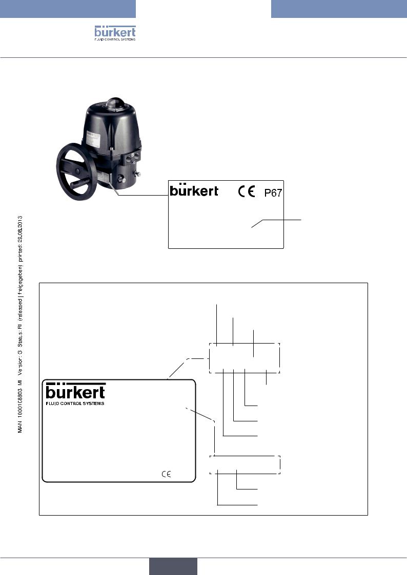
The rotary actuator is fitted with a rating plate which uniquely identifies the device and indicates the most important technical data.
Do not remove the rating plate from the rotary actuator!
It is essential for identification when installing and servicing the device.
The warranty is void without the rating plate.
13
English
Type 3004
Technical Data
6.5.1.Description of the rating plate.
|
|
|
|
Example: |
|
|
|
|
|
|
|
|
CE conformity |
|||
|
|
|
|
|
|
|
|
|
|
|
|
|
|
|
|
Protection class |
|
|
|
|
|
|
|
|
|
|
|
|
|
|
|
|
|
|
|
|
|
|
|
|
|
|
|
|
|
|
|
|
|
|
|
|
|
|
|
|
|
|
|
|
|
|
|
|
|
|
|
|
|
|
|
|
FLUID CONTROL SYSTEMS |
|
Year : 2007 |
|
|
Date of manufacture |
||||||
|
|
|
|
|
G 74653 INGELFINGEN |
|
|
|
||||||||
|
|
|
|
|
|
|
||||||||||
|
Type designation |
|
|
Type : 3004 |
182 384 |
|
|
|
Torque |
|||||||
|
|
|
|
|
|
|||||||||||
|
Serial number |
|
|
Serial n° : 086417 001 |
|
|
|
|||||||||
|
|
|
|
|
|
|||||||||||
|
Rotation angle |
|
|
90 ° |
|
|
|
75 Nm |
20 s |
|
|
Actuating time 90° |
||||
|
|
|
|
|
|
|
||||||||||
|
|
|
|
|
||||||||||||
|
Operating voltage |
|
|
24 V |
AC/DC Hz |
45 W |
|
|
Output |
|||||||
|
|
|
|
|||||||||||||
|
|
|
||||||||||||||
|
Current type |
|
|
|
|
|
|
|
|
|
|
|
|
|
|
|
|
|
|
|
|
|
|
|
|
|
|
|
|
|
|
||
|
|
|
|
|
|
|
|
|
|
|
|
|
|
|
|
|
Figure 3: |
Example of rating plate labelling |
|
|
|
|
|
|
|
|
|
|
|
|
|
||
Labelling ATEX rating plate
Example:
II 2 G D
Ex d IIB T5 tD A21 IP 67 T95°C
WARNUNG / WARNING / AVERTISSEMENT Ne pas ouvrir en zone explosible
Do not open in explosive area
Nicht in explosiver Zone öffnen
Ne pas ouvrir sous tension
Do not open while energized
Nicht unter Spannung öffnen
LCIE 07 ATEX 6078X |
0102 |
||
|
|
|
|
Licence number |
Inspection body |
||
Device group
Device category
Ignition protection type
II 2GD
Ex d IIB T5 tD A21
Zone
Temperature class (gas)
Explosion group
Ignition protection type
 IP 67 T95°C
Ignition protection type
Protection class
14 |
Figure 4: |
Example of ATEX rating plate |
English

Type 3004
Technical Data
6.6.General Technical Data
6.6.1.Mechanical data
Dimensions: |
See chapter “6.6.2. Dimensions” |
||||||
|
|
|
|
|
|
|
|
Weight: |
25 – 75 Nm; 4 kg |
||||||
|
100 – 300 Nm; 6.5 kg |
||||||
Housing material: |
Cover and housing made of epoxy-coated aluminium |
||||||
|
Axles and screws made of stainless steel |
||||||
|
Gears made of galvanized steel |
||||||
Actuating angle: |
90° (optional 180°, 270°) ± 5° |
||||||
Duty cycle: |
50% at maximum torque (optionally 80%) |
||||||
Manual emergency actuation: |
with open-end wrench on faces of the axle (up to 75 Nm); |
||||||
|
by handwheel (from 100 Nm) |
||||||
Working modes: |
Open/Closed mode or Three points mode |
||||||
|
(see figure “Figure 16” and “Figure 17”) |
||||||
|
|
|
|
|
|
|
|
15
English

Type 3004
Technical Data
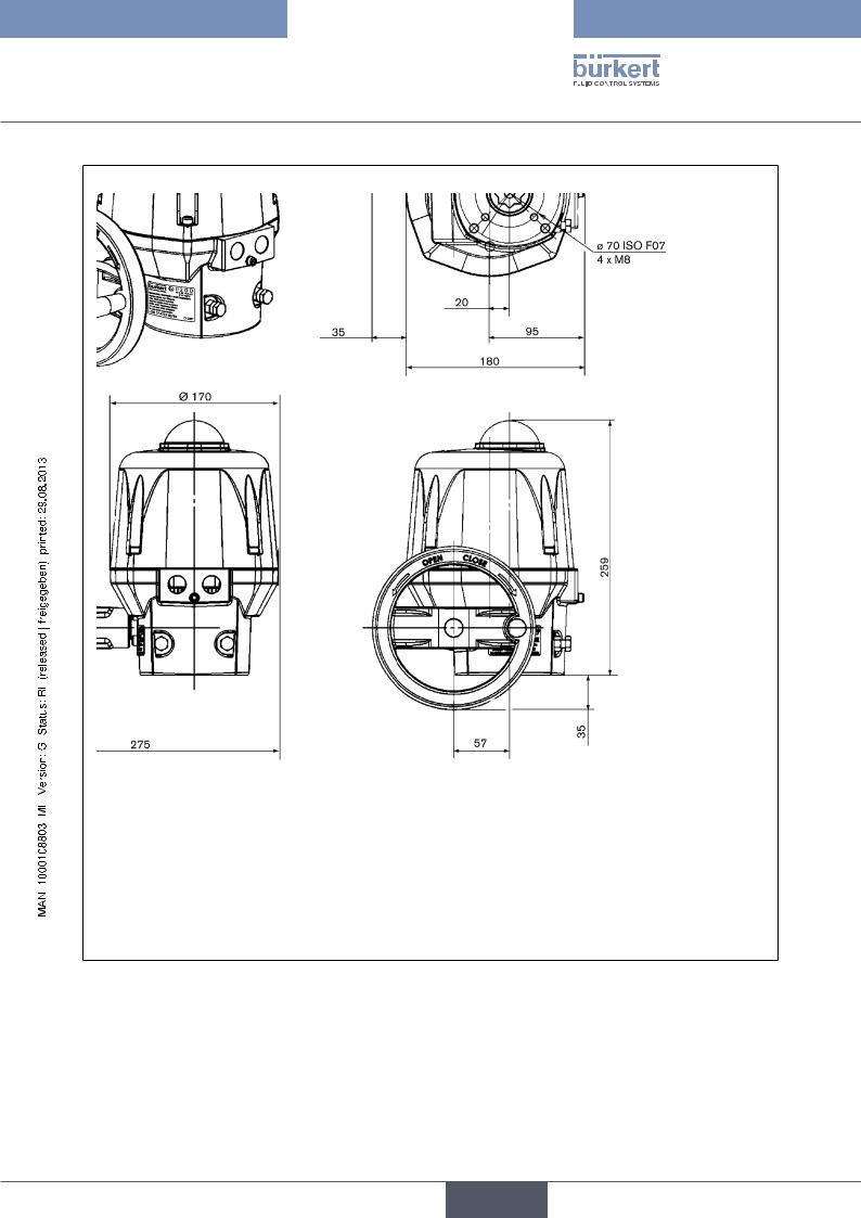
6.6.2.Dimensions
Motor 25 - 75 Nm
Figure 5: Dimensions Type 3004 at torque 25 – 75 Nm
16
English
Type 3004
Technical Data
Motor 100 – 300 Nm
Figure 6: Dimensions Type 3004 at torque 100 – 300 Nm
17
English

Type 3004
Technical Data
6.6.3.Electrical data
Connections: |
2 threaded connections ISO 20 |
Limit switches: |
2 limit switches for the motor |
|
2 potential-free limit switches (for position feedback) |
Output: |
max. 250 V AC / 5 A |
Electrical data for standard version without analogue signal and position controller version with 4 – 20 mA, 0 – 20 mA or 0 – 10 V analogue input signal
Torque [Nm] |
90° actuating time [s] |
Power input [W] |
Voltage / frequency |
|
[V / Hz] |
||||
|
|
|
||
|
|
|
|
|
25 |
7 |
45 |
100-240 / 50/60 (100-350 DC) |
|
|
|
|
|
|
|
|
|
15-30 AC (12-48 DC 1)) |
|
45 |
15 |
45 |
100-240 / 50/60 (100-350 DC) |
|
|
|
|
|
|
|
|
|
15-30 AC (12-48 DC 1)) |
|
75 |
20 |
45 |
100-240 / 50/60 (100-350 DC) |
|
|
|
|
|
|
|
|
|
15-30 AC (12-48 DC 1)) |
|
100 |
15 |
45 |
100-240 / 50/60 (100-350 DC) |
|
|
|
|
|
|
|
|
|
15-30 AC (12-48 DC 1)) |
|
150 |
30 |
45 |
100-240 / 50/60 (100-350 DC) |
|
|
|
|
|
|
|
|
|
15-30 AC (12-48 DC 1)) |
|
300 |
60 |
45 |
100-240 / 50/60 (100-350 DC) |
|
|
|
|
|
|
|
|
|
15-30 AC (12-48 DC 1)) |
We recommend an actuator designed with 1.5 times the maximum torque of the fitting (with 2 times the maximum torque for variable speed actuators)
1) The operating voltage must not drop below 11.5 V
18
English

Type 3004
Installation
7.INSTALLATION
7.1.Safety instructions
 DANGER!
Risk of electric shock!
There is a serious risk of injury when reaching into the device.
•Always disconnect the power and secure it from re-activation before removing the cover, disconnecting the gears or using the lever.
•Connect several rotary actuators always with phase separation via a switch!
•Protect the rotary actuators with a mains-operated fuse!
•Observe applicable accident prevention and safety regulations for electrical equipment!
 WARNING!
Danger - improper installation!
Improper installation may result in injuries as well as damage to the device and the area around it.
•Installation may be carried out by authorised technicians only and with the appropriate tools!
•Observe the specifications in chapter 6 Technical Data.
Danger due to unintentional activation of the device!
Unintentional activation of the device during installation may result in injuries and damage.
• Take appropriate measures to prevent the device from being accidentally actuated.
7.2.Installing the rotary actuator
 The rotary actuator is supplied with the presetting <Closed>.
The rotary actuator can be fitted to a ball valve or flap valve via the following fastening options:
•ISO F05 (4 x M6 with a flange Ø of 50 mm)
•ISO F07 (4 x M8 with a flange Ø of 70 mm)
•ISO F10 (4 x M10 with a flange Ø of 102 mm)
7.2.1.Shaft end
The sizes of the inner star shape of the shaft end depend on the size of the actuator. Only the standard size of the inner star shape is enclosed with each actuator (see table).
Actuator size [Nm] |
Standard size of the inner star shape [mm] |
|
|
25 |
17 / 11 |
45 / 75 |
22 / 14 |
100 / 150 / 300 |
22 / 17 |
19
English
Type 3004
Installation
The shaft ends of the ball valves / flap valves can be adjusted to the supplied star shape size with reducing sleeves which can be purchased separately.
The order numbers and an overview of the available reducing sleeves can be found in the chapter entitled “13. Accessories”.
Further information is available from your Bürkert sales office.
Important information for continuous function:
Do not attach rotary actuator head first!
Otherwise the medium may run out of the fitting into the actuator.
The required installation height of the rotary actuator above the ball valve / flap valve can be found in the chapter entitled Dimensions. Specify an additional distance of 100 mm.
Installation procedure:
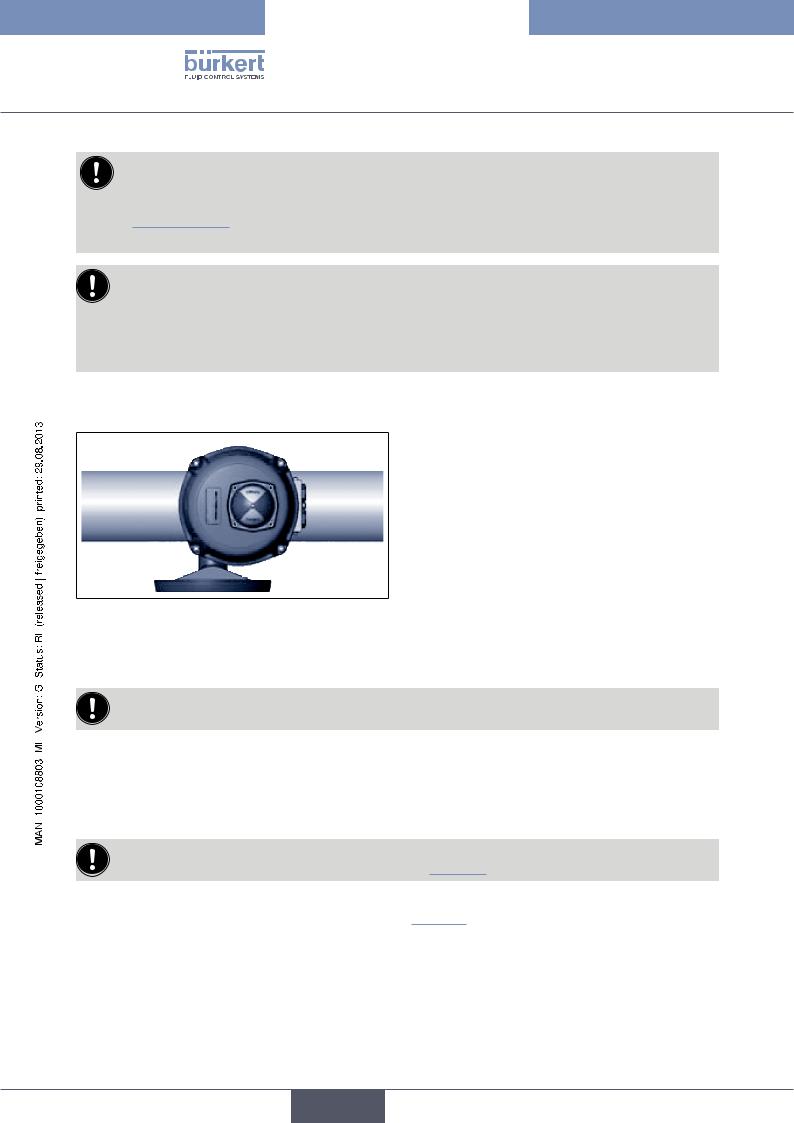
Figure 7: Standard installation
→→Ensure that the ball valve / the flap valve is in its closed position.
→→Carefully connect the rotary actuator to the shaft of the ball valve / flap valve.
When connecting the rotary actuator, ensure that it is not twisted and that the fastening threads of the rotary actuator are covered by the fastening bores of the ball valve / flap valve.
→→Screw the fastening screws into the fastening threads of the rotary actuator and tighten them firmly (max. 3 Nm).
7.2.2. Set mechanical end position limit (actuators 100 – 300 Nm)
The mechanical end position limits have been preset at the factory and glued on with Loctite. However, they can be adjusted by turning the screws M8 Pos. 17 (see “Figure 2”). Then the nuts must be glued on again.
→→Loosen the M8 nuts on the mechanical limit stops 17 (see “Figure 2”) and adjust the mechanical end position limits.
→→Glue nuts on again with Loctite (e. g. Loctite 577).
20
English
Type 3004
Installation
7.2.3.Adjusting limit switch contacts
 The two upper limit switch contacts have been set to 0 – 90° at the factory.
Removing position indicator and hood
 1
1
Figure 8: |
Removing glass hood |
Figure 9: |
Removing position |
Figure 10: |
Removing hood |
|
|
|
indicator |
|
|
Procedure:
→→Remove glass hood of the position indicator 1 including the sealing ring by loosening the four fastening screws and remove the glass hood (see “Figure 8”).
→→Remove position indicator (see “Figure 9”).
→→Remove hood 2 by loosening the four fastening screws 3 (see “Figure 10”).
Adjusting cams for limit switch contacts
Cam |
Cam |
|
Key |
|
Key |
|
Adjustment travel |
|
Adjustment travel |
Figure 11: |
Adjusting limit switch clockwise |
Figure 12: |
Adjusting limit switch anti-clockwise |
Procedure:
→→Adjust the two upper cams with a suitable key (see “Figure 11” and “Figure 12” ).
→→On completion of the adjustment work, re-attach the hood 3, the position indicator, the seal and the glass hood 1.
21
English
Type 3004
Installation
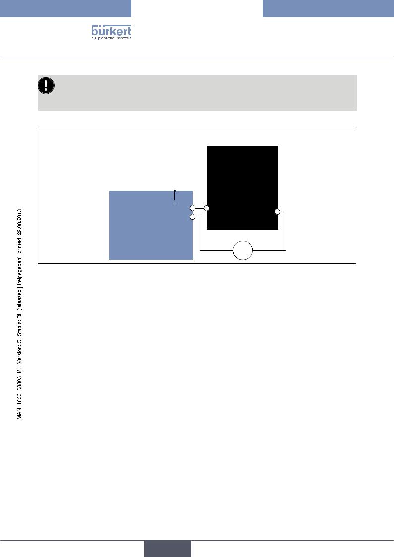
The rotary actuator is supplied ex works with the following settings:
• The limit switch CLOSED (FCF) is actuated by the cam (closed position).
• The limit switch OPEN (FCO) is preset to a rotation angle of 90°.
|
|
|
|
|
|
|
|
|
|
|
|
|
|
Feedback |
|
|
|
|
||||
|
|
|
|
|
|
|
|
|
|
|
|
|
|
|
|
|
|
|
|
|
|
|
|
|
|
|
|
|
|
|
|
|
|
|
|
|
4-6 |
|
5 |
|
7 |
|
|||
|
|
|
|
|
|
|
|
|
|
|
|
|
|
|
FC2 |
|
|
|
|
|
|
|
|
|
|
|
|
|
|
|
|
|
|
|
|
|
|
|
|
|
|
|
|
||
Power supply and control |
|
|
|
FC1 |
|
|
|
|
|
|
||||||||||||
|
|
|
|
|
|
|
|
|
||||||||||||||
|
|
|
|
|
|
T/E |
|
|
|
|
|
|
|
|
|
|||||||
|
1 |
|
2 |
|
3 |
|
D |
|
|
|
|
|
|
|||||||||
|
|
|
|
|
|
|
|
|
|
|
|
|
|
|
|
|||||||
|
|
|
|
|
|
|
|
|
|
|
|
|
|
|
||||||||
|
|
|
|
|
|
|
|
|
|
|
|
|
|
|
|
|
|
|
||||
|
|
|
|
|
|
|
|
|
|
C |
C |
|
|
FCF |
|
|
|
|
|
|
||
|
|
|
|
|
|
|
|
|
|
|
|
|
|
|
|
|
|
|||||
|
|
|
|
|
|
|
|
|
|
|
|
|
|
|
|
|
|
|||||
|
|
|
|
|
|
|
|
|
|
D |
|
|
|
|
|
B |
||||||
|
|
|
|
|
|
|
|
|
|
A |
|
|
|
|
|
|
||||||
|
|
|
|
|
|
|
|
|
|
|
|
|
FC0 |
|
|
|
|
|
|
|||
|
|
|
|
|
|
|
|
|
|
|
|
|
|
|
|
|
|
|
|
|
||
Motor
=
Figure 13: Internal wiring of actuator
22
English
Type 3004
Installation
8.INSTALLATION
8.1.Safety instructions
 WARNING!
Danger - improper installation!
Improper installation may result in injuries as well as damage to the device and the area around it.
•Fluid and electrical installations may be carried out by authorised technicians only and with the appropriate tools!
Danger due to unintentional activation of the equipment!
Unintentional activation of the equipment during installation work may result in injuries and/or damage.
• Take appropriate measures to prevent the equipment from being unintentionally activated.
8.2.Electrical installation
 DANGER!
Risk of electric shock!
There is a serious risk of injury when reaching into the device.
•Before starting work, always switch off the power supply and safeguard to prevent re-activation!
•Observe applicable accident prevention and safety regulations for electrical equipment!
•Attach earthing cable via the earthing screw!
Check on the rating plate of the rotary actuator whether the indicated voltage corresponds with the mains voltage.
Cables with a diameter of 7 to 12 mm are permitted for the electrical installation. The utilized cables must have an upper limit temperature of at least 80 °C.
Use only ATEX-approved cables and cable bushings.
Preparatory work:
→→Remove stainless steel screws 3 for the hood 2 and carefully remove the hood (see “Figure 1” and “Figure 2”).
8.2.1. |
Earth connection on outside or inside |
|
||||||||
The earthing cable for the power supply and control must be attached with the earthing screw 16 (M5) to the outer |
|
|||||||||
housing (see “Figure 1” and “Figure 2”). |
|
|||||||||
Procedure: |
|
|
|
|
|
|
|
|
||
→→Loosen earthing screw 16 and attach eyelet of the earthing cable to the earthing screw (see “Figure 1” and |
|
|||||||||
|
“Figure 2”). |
|
|
|
||||||
|
|
|
|
|
|
|
||||
→→Optionally the earthing screw can be connected to Pos. A of the power supply card. |
|
|||||||||
→→To do this, loosen earthing screw and attach eyelet of the earthing cable with the earthing screw (see “Figure |
|
|||||||||
|
14” |
and |
“Figure 15”) |
. |
|
|
23 |
|||
|
|
|
||||||||
English

Type 3004
Installation
8.2.2.100-240 V AC (100-350 V DC) or 15-30 V AC (12-48 V DC) standard version
The power supply voltage of the actuator is 15-30 V AC (12-48 V DC) or 100-240 V AC (100-350 V DC).
Always observe the specifications on the rating plate!
H
F
E
 D
D
A C B C
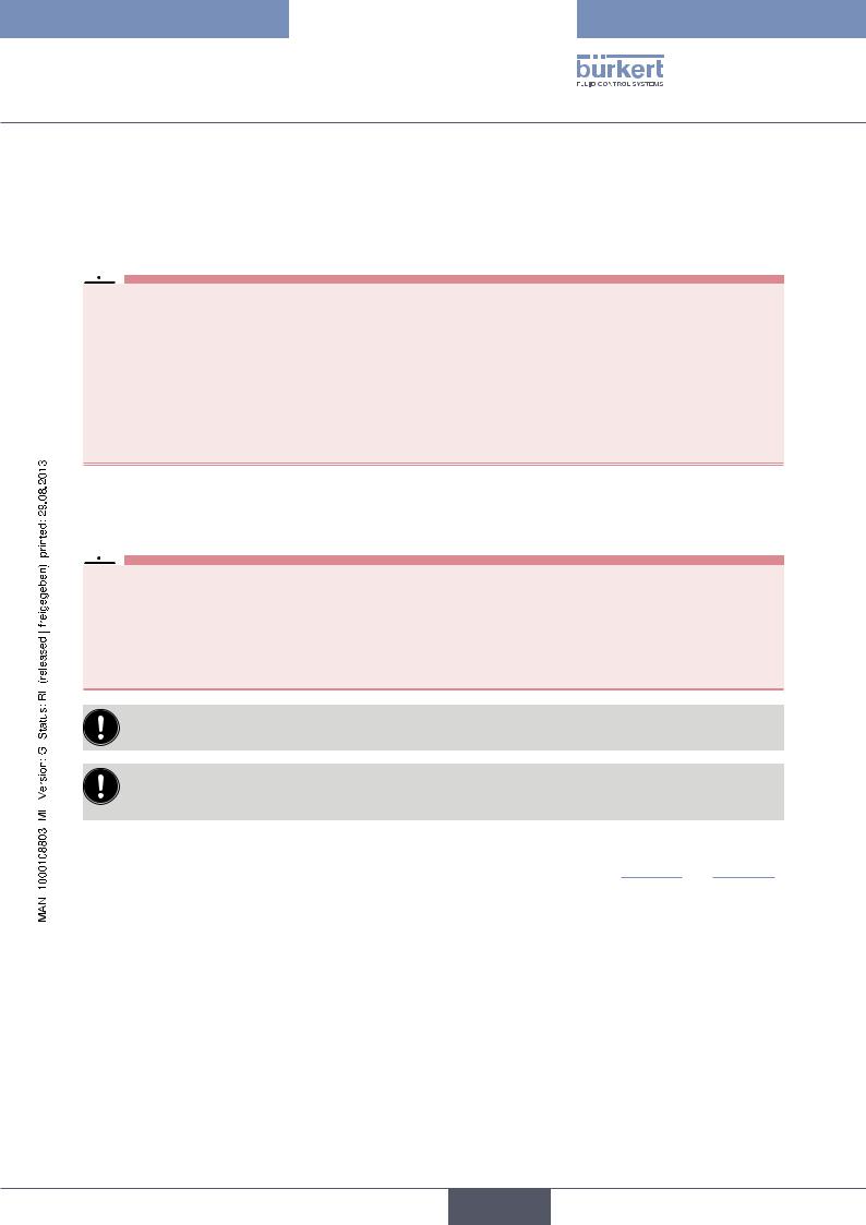
Figure 14: Power supply circuit board 15-30 V 50/60 Hz (12-48 V DC)
No. Designation
AScrew for earthing
BConnections for control and power supply
CFuse
DLED 1: Microprocessor OK
H
F
E
 D
D
A C B C
Figure 15: Power supply circuit board 100-240 V 50/60 Hz (100-350 V DC)
No. |
Designation |
|
|
E |
LED 2: Error message |
FLED 3: Power on
HConnection 24 V DC
The rotary actuator can be connected and operated in two different modes:
1.Three points mode
2.Open / Closed mode
24
English

Type 3004
Installation
N Ph
-+
Auf Zu


 T/E 1
T/E 1 
 2
2  3
3 

N Ph
-+
Auf
T/E
1  2
2 
 3
3
Figure 16: |
Three points mode |
Figure 17: |
Open / Closed mode / Emergency current |
|
|
|
model |
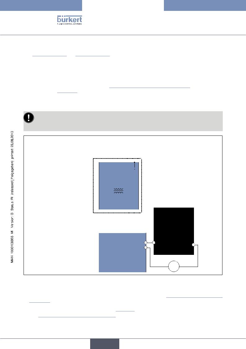
If voltage is applied simultaneously to terminals 2 and 3, terminal 2 is the leading one and the actuator moves to the OPEN position.
Procedure:
→→Loosen left cable gland 15 (see “Figure 1” and “Figure 2”) and feed through the cable to be connected.
→→Connect cable according to the required control type (see “Figure 16” and “Figure 17”) to the terminal strip Pos. B of the power supply card (see “Figure 14” and “Figure 15”).
Operating principle for Open / Closed mode (see “Figure 17”) :
•Switch open = actuator closes
•Switch closed = actuator opens
Connecting feedback
 The limit switches for the feedback are suitable for a maximum voltage of 250 V AC/DC – 5 A.
The rotary actuator features two additional limit switch contacts which are supplied by the factory in an open position. These can be used for the feedback of the rotary actuator.
|
|
|
|
|
|
|
|
|
|
|
|
|
|
Feedback |
|
|
|
|
||||
|
|
|
|
|
|
|
|
|
|
|
|
|
|
|
|
|
|
|
|
|
|
|
|
|
|
|
|
|
|
|
|
|
|
|
|
|
4-6 |
|
5 |
|
7 |
|
|||
|
|
|
|
|
|
|
|
|
|
|
|
|
|
|
FC2 |
|
|
|
|
|
|
|
|
|
|
|
|
|
|
|
|
|
|
|
|
|
|
|
|
|
|
|
|
||
Power supply and control |
|
|
|
FC1 |
|
|
|
|
|
|
||||||||||||
|
|
|
|
|
|
|
|
|
||||||||||||||
|
|
|
|
|
|
T/E |
|
|
|
|
|
|
|
|
|
|||||||
|
1 |
|
2 |
|
3 |
|
D |
|
|
|
|
|
|
|||||||||
|
|
|
|
|
|
|
|
|
|
|
|
|
|
|
|
|||||||
|
|
|
|
|
|
|
|
|
|
|
|
|
|
|
|
|
|
|
||||
|
|
|
|
|
|
|
|
|
|
C |
C |
|
|
FCF |
|
|
|
|
|
|
||
|
|
|
|
|
|
|
|
|
|
|
|
|
|
|
|
|
|
|||||
|
|
|
|
|
|
|
|
|
|
|
|
|
|
|
|
|
|
|||||
|
|
|
|
|
|
|
|
|
|
D |
|
|
|
|
|
B |
||||||
|
|
|
|
|
|
|
|
|
|
A |
|
|
|
|
|
|
||||||
|
|
|
|
|
|
|
|
|
|
|
|
|
FC0 |
|
|
|
|
|
|
|||
|
|
|
|
|
|
|
|
|
|
|
|
|
|
|
|
|
|
|
|
|
||
Motor
=
Figure 18: Internal wiring of actuator
25
English
Type 3004
Installation
The limit switch contacts are actuated via two cams no. 13 (see “Figure 1”, page 10 and “Figure 2”, page 11).
•The white cam is used to record the opening process (FC1).
•The black cam is used to record the closing process (FC2).
Procedure:
→→Connect cable to the terminal strip 12 (see “Figure 1”, page 10 and “Figure 2”, page 11) according to the schematic (see “Figure 18”).
8.2.3.Version with analog signal input
The power supply voltage of the actuator is 15-30 V AC (12-48 V DC) or 100-240 V AC (100-350 V DC).
Always observe the specifications on the rating plate!
0 – 20 mA / 4 – 20 mA / 0 – 10 V
Power supply
100-240 V AC |
|
N |
|
|
|
|
Ph |
|
|
|
|
|
||
- |
|
|
|
+ |
|
T/E |
||||||||
(100-350 V DC) |
|
|
|
|
|
|
|
|
|
|
||||
|
|
|
|
|
|
|
|
|
|
|
|
|
|
|
or |
|
|
|
|
|
|
|
|
|
|
|
|
|
|
15-30 V AC |
|
|
|
|
|
|
|
|
|
|
|
|
|
|
|
1 |
|
2 |
|
3 |
|
|
|
|
|
||||
|
|
|
|
|
|
|
|
|||||||
(12-48 V DC)) |
|
|
|
|
|
|
|
|
|
|
|
|
|
|
|
|
|
|
|
|
|
|
|
|
|
|
|
|
|
|
|
|
|
|
|
|
|
|
|
|
|
|
|
|
|
|
|
|
|
|
|
|
|
|
|
|
|
|
|
|
|
|
|
|
|
|
|
|
|
|
|
|
|
|
|
|
|
|
Feedback |
|
|
|
|||||
|
|
|
|
|
|
|
|
|
|
|
|
|
|
|
|
|
|
|
|
|
|
||||||
|
|
|
|
|
|
|
|
|
|
|
|
|
|
|
|
|
|
|
|
|
|
|
|
|
|
|
|
|
|
|
|
|
|
|
17 |
|
|
18 |
|
|
|
|
|
4-6 |
|
|
5 |
|
7 |
|
|||||
|
|
|
|
|
|
|
|
|
|
|
|
|
|
|
|
|
|
|
|
|
|
|
|
||||
|
|
|
|
|
|
|
|
|
|
|
|
|
|
|
|
|
|
|
FC2 |
|
|
|
|
|
|
|
|
|
|
|
|
|
|
|
|
|
|
|
|
|
|
|
|
|
|
|
|
|
|
|
|
|
|
||
Power supply |
|
|
|
|
|
|
N |
|
|
Ph |
|
|
|
|
|
|
|
|
|
|
|
|
|
||||
|
|
|
|
|
|
|
|
|
|
|
|
|
|
|
|
|
|
|
|
|
|
|
|||||
|
|
|
|
- |
|
+ |
|
|
|
|
|
|
FC1 |
|
|
|
|
|
|
|
|||||||
|
|
|
|
|
|
|
|
|
|
|
|
|
|||||||||||||||
24 V DC |
|
|
|
|
|
|
|
|
|
|
|
|
|
|
|
|
|
|
|
|
|
|
|
|
|
||
|
|
|
|
|
|
|
|
|
|
|
|
|
|
|
|
|
|
|
|
|
|
|
|
|
|||
|
|
|
|
|
|
|
|
|
|
|
|
|
|
|
|
|
|
|
|
|
|
|
|
|
|
|
|
|
|
|
|
|
|
17 |
|
|
18 |
|
|
|
|
D |
|
|
|
|
|
|
|
||||||
|
|
|
|
|
|
|
|
|
|
|
|
|
|
|
|
|
|
|
|
||||||||
+ |
|
|
|
|
|
|
|
|
|
|
|
|
|
|
|
|
|
|
FCF |
|
|
|
|
|
|
|
|
|
|
16 |
|
|
|
|
|
|
|
|
C |
|
C |
|
|
|
|
|
|
|
|
|
|||||
|
|
|
|
|
|
|
|
|
|
|
|
|
|
|
|
|
|
|
|||||||||
Input |
|
|
|
|
|
|
|
|
|
|
|
|
|
|
D |
|
|
|
|
|
|
B |
|||||
|
|
|
|
|
|
|
|
|
|
|
|
|
A |
|
|
|
|
|
|
||||||||
- |
|
|
15 |
|
|
|
|
|
|
|
|
|
|
FC0 |
|
|
|
|
|
|
|
||||||
|
|
|
|
|
|
|
|
|
|
|
|
|
|
|
|
|
|
||||||||||
- |
|
|
|
|
|
|
|
|
|
|
|
|
|
|
|
|
|
|
|
|
|
|
|
|
|
|
|
|
|
14 |
|
|
|
|
|
|
|
|
|
|
|
|
|
|
|
|
|
|
|
|
|
|
|||
|
|
|
|
|
|
|
|
|
|
|
|
|
|
|
|
|
|
|
|
|
|
|
|||||
Feedback |
|
|
|
|
|
|
|
|
|
|
|
|
|
|
|
|
|
|
|
|
|
|
|
|
|
|
|
|
|
|
|
|
|
|
|
|
|
|
|
|
|
|
|
|
|
|
|
|
|
|
|
|
|
|
|
+ |
|
|
13 |
|
|
|
|
|
|
|
|
|
|
|
|
|
Motor |
|
|
|
|||||||
|
|
|
|
|
|
|
|
|
|
|
|
|
|
|
|
||||||||||||
|
|
|
|
|
|
|
|
|
|
|
|
|
|
|
|
|
|
|
|
|
= |
|
|
|
|
|
|
|
|
|
|
|
|
|
|
|
|
|
|
|
|
|
|
|
|
|
|
|
|
|
|
|
|
|
|
Figure 19: Circuit diagram
Procedure:
→→Loosen left cable gland 15 and feed through the cable to be connected (see “Figure 1”, page 10 and “Figure 2”, page 11).
→→Connect cable according to the circuit diagram (see “Figure 19”) to the terminal strip Pos. 14 of the power supply card
(see “Figure 1”, page 10 and “Figure 2”, page 11).
26
English
Type 3004
Installation
Connecting feedback
 The limit switches for the feedback are suitable for a maximum voltage of 250 V AC/DC – 5 A.
The rotary actuator features two limit switch contacts which are supplied by the factory in an open position. These can be used for the feedback of the rotary actuator.
The limit switch contacts are actuated via two cams no. 13 (see “Figure 1”, page 10 and “Figure 2”, page 11).
•The white cam is used to record the opening process (FC1).
•The black cam is used to record the closing process (FC2).
Procedure:
→→Connect cable to the terminal strip 12 (see “Figure 1”, page 10 and “Figure 2”, page 11) according to the schematic (see “Figure 19”).
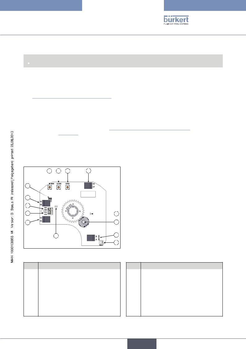
8.3.Control card
For rotary actuator with analogue control
D E F A
I
H |
|
G |
K |
C |
L |
J |
M |
|
N |
Figure 20: Control card (24 V DC)
No. |
Designation |
|
No. |
Designation |
|
|
|
|
|
A |
24V DC power supply |
|
H |
K2 plug-in jumper |
|
|
|
|
|
B |
Connection terminals transducer |
|
I |
K3 plug-in jumper |
|
|
|
|
|
C |
Connection terminals feedback |
|
J |
Green and red LEDs |
|
|
|
|
|
D |
Adjusting button <MEM> |
|
K |
Yellow LED: power supply display |
|
|
|
|
|
E |
Adjusting button <CLOSE> |
|
L |
Potentiometer |
|
|
|
|
|
F |
Adjusting button <OPEN> |
|
M |
Connection motor |
|
|
|
|
|
G |
K1 plug-in jumper |
|
N |
Connection heating resistor |
27
English
Type 3004
Installation
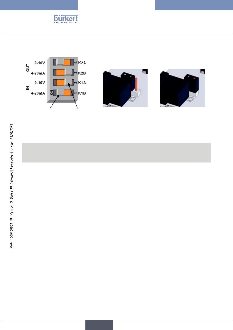
8.3.1.The position of the plug-in jumpers
ON |
OFF |
|
|
|
|
|
|
|
|
|
||
(turned on) |
(turned off) |
|
|
|
|
|
|
|
|
|
||
|
|
|
|
|
|
|
|
|
|
|
||
Figure 21: Plug-in jumper K1 / K2 |
|
Figure 22: |
Plug-in jumper K3 |
Figure 23: Plug-in jumper K3 |
||||||||
|
|
|
|
|
|
|
OFF |
|
|
|
ON |
|
|
|
|
|
|
|
|
|
|
|
|||
|
|
|
|
Plug-in jumper K1 |
Plug-in jumper K2 |
|
Plug-in |
|||||
|
|
|
|
|
|
|
|
|
|
|
|
|
Transducer |
|
Feedback |
|
|
A |
|
B |
A |
|
B |
|
jumper |
|
|
|
|
|
|
|
|
K3 |
||||
|
|
|
|
|
|
|
|
|
|
|
|
|
|
|
|
|
|
|
|
|
|
|
|
|
|
0 – 10 V |
|
0 – 10 V |
|
ON |
|
OFF |
ON |
|
OFF |
|
OFF |
|
|
|
|
|
|
|
|
|
|
|
|
|
|
0 – 10 V |
|
0 – 20 mA |
|
ON |
|
OFF |
OFF |
|
ON |
|
OFF |
|
|
|
|
|
|
|
|
|
|
|
|
|
|
0 – 10 V |
|
4 – 20 mA |
|
ON |
|
OFF |
OFF |
|
ON |
|
ON |
|
|
|
|
|
|
|
|
|
|
|
|
|
|
0 – 20 mA |
|
0 – 10 V |
|
OFF |
|
ON |
ON |
|
OFF |
|
OFF |
|
|
|
|
|
|
|
|
|
|
|
|
|
|
0 – 20 mA |
|
0 – 20 mA |
|
OFF |
|
ON |
OFF |
|
ON |
|
OFF |
|
|
|
|
|
|
|
|
|
|
|
|
|
|
0 – 20 mA |
|
4 – 20 mA |
|
OFF |
|
ON |
OFF |
|
ON |
|
ON |
|
|
|
|
|
|
|
|
|
|
|
|
|
|
4 – 20 mA |
|
0 – 10 V |
|
OFF |
|
ON |
ON |
|
OFF |
|
OFF |
|
|
|
|
|
|
|
|
|
|
|
|
|
|
4 – 20 mA |
|
0 – 20 mA |
|
OFF |
|
ON |
OFF |
|
ON |
|
OFF |
|
|
|
|
|
|
|
|
|
|
|
|
|
|
4 – 20 mA |
|
4 – 20 mA |
|
OFF |
|
ON |
OFF |
|
ON |
|
ON |
|
|
|
|
|
|
|
|
|
|
|
|
|
|
28
English

Type 3004
Installation
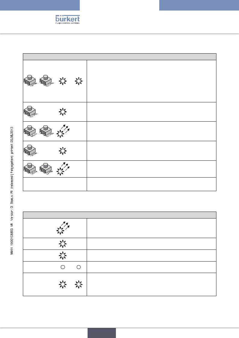
8.3.2.Parameterization steps
Specify direction of rotation of the shut-off valve
Normal direction of rotation (preset)
|
|
|
→→Press <OPEN> push-button and switch on the card (hold down |
|
|
|
push-button). |
|
|
G |
The GREEN LED lights up. |
|
|
||
|
|
||
|
|
|
→→Release <OPEN> push-button and disconnect the card from the power |
|
|
|
supply. |
|
|
|
|
Reverse direction of rotation
→→Press <CLOSE> push-button and switch on the card (hold down push-button).
R |
The RED LED lights up. |
|
→→Release <CLOSE> push-button and disconnect the card from the |
|
power supply. |
Specify control signal type
Control signal when voltage 0 – 10 V
→→Press <MEM> push-button and switch on the card (hold down push-button).
R |
The RED LED lights up 3x. |
|
|
|
→→Release <MEM> push-button and disconnect the card from the |
|
power supply. |
Control signal when current 0 – 20 mA
→→Press <MEM> and <OPEN> push-buttons and switch on the card (hold down push-button).
R |
The RED LED lights up 3x. |
|
|
|
→→Release <MEM> and <OPEN> push-buttons and disconnect the |
|
card from the power supply. |
Control signal when current 4 – 20 mA (preset)
→→Press <MEM> and <CLOSE> push-buttons and switch on the card (hold down push-button).
R |
The RED LED lights up 3x. |
|
|
|
→→Release <MEM> and <CLOSE> push-buttons and disconnect the |
|
card from the power supply. |
29
English
Type 3004
Installation
Learning mode
Specify end positions
|
|
→→Press <OPEN> and <CLOSE> push-buttons and switch on the card |
|
|
(hold down push-button). |
|
|
The RED and the GREEN LEDs light up. |
G |
R |
→→Release <OPEN> and <CLOSE> push-buttons. |
|
|
Both LEDs go out. |
|
|
Learning mode is selected. |
|
|
→→Press <CLOSE> push-button to move the shut-off valve into the |
R |
|
closed position. |
|
|
|
|
|
The RED LED lights up. |
|
|
→→Press <MEM> and <CLOSE> push-buttons to save the closed |
R |
|
position. |
|
|
|
|
|
The RED LED lights up 2x. |
|
|
→→Press <OPEN> push-button to move the shut-off valve into the open |
G |
|
position. |
|
|
|
|
|
The GREEN LED lights up. |
|
|
→→Press <MEM> and <OPEN> push-buttons to save the open position. |
G |
|
The GREEN LED lights up 2x. |
|
|
|
|
|
All positions are now saved. |
|
|
→→Disconnect the card from the power supply. |
8.3.3. Normal operation
Display normal operation
|
|
→→Switch on card. |
G |
|
The GREEN LED lights up 3x to indicate that the start process has been |
|
|
implemented correctly. |
G |
|
In normal operation the GREEN LED lights up when the rotary actuator |
|
opens the shut-off valve. |
|
|
|
|
R |
|
The RED LED lights up when the rotary actuator closes the shut-off valve. |
G |
R |
If neither of the LEDs is lit, the actuator is not actuated. |
|
|
The RED and the GREEN LEDs light up if the torque is too high and the |
G |
R |
rotary actuator stops. |
→→Change direction of rotation of the rotary actuator or switch over the |
||
|
|
voltage OPEN/CLOSED to restart the rotary actuator! |
30
English
 Loading...