


Operating Instructions
Bedienungsanleitung
Instructions de Service
Type 8630
TOP Control Continuous

We reserve the right to make technical changes without notice. Technische Änderungen vorbehalten.
Sous resérve de modification techniques.
© 2001 Bürkert Werke GmbH & Co KG.
Operating Instructions 0507/11_EU-EN_00804575

CONTENTS
Overall Operating Instructions
TOP Control Continuous 8630
GENERAL NOTES |
|
Symbols .......................................................................................................................................................................................................................................................... |
10 |
Intended use ............................................................................................................................................................................................................................................ |
10 |
Safety notes .............................................................................................................................................................................................................................................. |
10 |
Protection from damage by electrostatic charging ......................................................................................................................... |
11 |
Scope of delivery .............................................................................................................................................................................................................................. |
11 |
Warranty conditions ...................................................................................................................................................................................................................... |
11 |
Master code .............................................................................................................................................................................................................................................. |
12 |
Transport, storage ............................................................................................................................................................................................................................ |
12 |
Disposal ......................................................................................................................................................................................................................................................... |
12 |
SYSTEM DESCRIPTION |
|
Valve types ................................................................................................................................................................................................................................................. |
14 |
Characteristics of the valve types ...................................................................................................................................................................................... |
15 |
Construction of TOP Control Continuous ..................................................................................................................................................... |
16 |
Illustrations (cover removed) ................................................................................................................................................................................................... |
16 |
Design features ..................................................................................................................................................................................................................................... |
17 |
Functional diagram as a positioner with single-acting actuator ............................................................................................................ |
18 |
Operation as a positioner ..................................................................................................................................................................................................... |
19 |
Schematic representation of positioning control .................................................................................................................................................. |
20 |
Characteristics of the positioner software .................................................................................................................................................................. |
21 |
* Alternative chapters or functions depending on device configuration
8630 - 1

CONTENTS
*Operation as a process controller (option)............................................................................................................................................... |
22 |
Example of process control: TOP Control Continuous with sensor ................................................................................................... |
22 |
Schematic representation of process control ......................................................................................................................................................... |
23 |
Characteristics of the process controller software ............................................................................................................................................. |
24 |
* Operation as a flow rate controller (option).......................................................................................................................................... |
25 |
Characteristics of the flow rate controller software ......................................................................................................................................... |
25 |
Schematic representation of process control with flow rate controller ....................................................................................... |
26 |
* Interfaces of the TOP Control Continuous in the multipole variant .................................................................. |
27 |
* Interfaces of the TOP Control Continuous in the variants with |
|
cable bushings .................................................................................................................................................................................................................................. |
28 |
Technical data ........................................................................................................................................................................................................................................ |
29 |
Safety settings on failure of auxiliary electrical or pneumatic energy ......................................................................................... |
29 |
Factory settings on the TOP Control Continuous ............................................................................................................................................. |
30 |
Data of the TOP Control Continuous ............................................................................................................................................................................. |
31 |
FIRST COMMISSIONING |
|
Fluidic installation ............................................................................................................................................................................................................................. |
34 |
*Electrical installation - multipole connector ............................................................................................................................................ |
35 |
*Electrical installation - connection terminals for cable bushings............................................................................ |
36 |
Basic settings of the TOP Control Continuous..................................................................................................................................... |
37 |
Settings in the menu items ....................................................................................................................................................................................................... |
38 |
Entering the position setpoint in the AUTOMATIC mode .......................................................................................................................... |
38 |
Manual opening and closing of the valve actuator in the MANUAL mode ............................................................................. |
39 |
INSTALLATION |
|
Installation of the valve ............................................................................................................................................................................................................ |
42 |
Turning the TOP Control Continuous.................................................................................................................................................................. |
42 |
Procedure ................................................................................................................................................................................................................................................... |
42 |
Fluidic connection of the TOP Control Continuous ....................................................................................................................... |
43 |
* Alternative chapters or functions depending on device configuration
2 - 8630

CONTENTS
*Electrical connection - multipole connectors ....................................................................................................................................... |
44 |
Marking of the multipole plugs or sockets and the contacts ................................................................................................................... |
44 |
Output signals for SPS (circular plug M 16) ............................................................................................................................................................. |
45 |
Operating voltage (circular plug M 12) ............................................................................................................................................................................ |
45 |
Inductive proximity switches (circular socket M 8) ........................................................................................................................................... |
45 |
Process value (circular plug M 8) ....................................................................................................................................................................................... |
46 |
Process value with the option flow rate controller (2 circular plugs M 8) |
|
Option: with temperature sensor input (3 circular plugs M 8) .............................................................................................................. |
46 |
*Electrical connection - terminals for cable bushing.................................................................................................................... |
47 |
Connection PCB of the TOP Control Continuous with screw terminals and jumpers ................................................ |
47 |
Terminal configuration with cable bushings ............................................................................................................................................................ |
47 |
Choice of binary outputs or process value input ............................................................................................................................................... |
48 |
*Setting the inductive proximity switches (option) ........................................................................................................................... |
50 |
Opening the housing of the TOP Control Continuous ................................................................................................................................. |
50 |
Positioning the inductive proximity switches .......................................................................................................................................................... |
50 |
OPERATION AND CONTROLLER FUNCTIONS |
|
Operating and display elements ................................................................................................................................................................................ |
52 |
Operating levels .................................................................................................................................................................................................................................. |
52 |
Commissioning and set-up as a positioner ............................................................................................................................................... |
53 |
Procedure for specifying the basic settings ............................................................................................................................................................ |
53 |
Main menu for the settings on commissioning .................................................................................................................................................... |
54 |
Description of the procedure .................................................................................................................................................................................................. |
55 |
Configuring the supplementary functions .................................................................................................................................................... |
59 |
Keys in the configuration level .............................................................................................................................................................................................. |
59 |
Configuration menu .......................................................................................................................................................................................................................... |
59 |
Supplementary functions ........................................................................................................................................................................................................... |
62 |
Operating the process............................................................................................................................................................................................................... |
86 |
Changeover between operating modes ...................................................................................................................................................................... |
86 |
Operating mode AUTOMATIC....................................................................................................................................................................................... |
87 |
Meaning of the keys in the AUTOMATIC mode .................................................................................................................................................. |
87 |
Display of the AUTOMATIC mode ..................................................................................................................................................................................... |
87 |
Operating mode MANUAL .................................................................................................................................................................................................. |
88 |
Meaning of the keys in the MANUAL mode ............................................................................................................................................................ |
88 |
Display of the MANUAL mode .............................................................................................................................................................................................. |
88 |
* Alternative chapters or functions depending on device configuration
8630 - 3

CONTENTS
OPERATING THE PROCESS CONTROLLER
Factory settings on the process controller................................................................................................................................................... |
90 |
Setting up a process control system .................................................................................................................................................................... |
90 |
Self-parametrization of the positioner - X.TUNE............................................................................................................................... |
91 |
Supplementary function P.CONTRL .................................................................................................................................................................... |
91 |
Basic settings of the function P.CONTRL................................................................................................................................................................... |
92 |
P.Q’LIN - Starting the routine for linearization of the process curve ..................................................................... |
105 |
Display during call-up and execution of the routine .......................................................................................................................................... |
105 |
P.CO TUNE - Self-optimization of the process controller (process tune) ..................................................... |
106 |
P.CO LEAK - Leakage characteristic for flow rate control ................................................................................................... |
110 |
Operating the process ............................................................................................................................................................................................................... |
112 |
Changeover between the operating modes ................................................................................................................................................................ |
112 |
Operating mode AUTOMATIC ....................................................................................................................................................................................... |
113 |
Meaning of the keys ......................................................................................................................................................................................................................... |
113 |
Displays ........................................................................................................................................................................................................................................................ |
113 |
Operating structure and procedures .................................................................................................................................................................................. |
113 |
Manually changing the process setpoint ...................................................................................................................................................... |
114 |
Operating mode MANUAL .................................................................................................................................................................................................. |
114 |
Meaning of the keys ......................................................................................................................................................................................................................... |
114 |
Displays ........................................................................................................................................................................................................................................................ |
115 |
Operating structure and procedures .................................................................................................................................................................................. |
115 |
PROFIBUS DP
General notes......................................................................................................................................................................................................................................... |
118 |
Technical data ....................................................................................................................................................................................................................................... |
118 |
Safety settings on bus failure ......................................................................................................................................................................................... |
118 |
Interfaces....................................................................................................................................................................................................................................................... |
119 |
Electrical connections ............................................................................................................................................................................................................... |
119 |
Connection with one plugged bus connector ........................................................................................................................................................... |
119 |
Connection with 2 plugged bus connectors .............................................................................................................................................................. |
120 |
Operating voltage (circular plug M12) ............................................................................................................................................................................. |
120 |
Bus connection (circular socket M12) ............................................................................................................................................................................ |
120 |
4 - 8630

|
CONTENTS |
Inductive proximity switches (circular socket M8) ............................................................................................................................................. |
121 |
Process value (circular plug M8) ......................................................................................................................................................................................... |
121 |
Termination connection for PROFIBUS systems ................................................................................................................................................ |
122 |
Settings on the TOP Control Continuous ..................................................................................................................................................... |
123 |
Explanation of the menu items .............................................................................................................................................................................................. |
124 |
Functional deviations from the standard version .............................................................................................................................. |
124 |
Configuration in the Profibus DP master ...................................................................................................................................................... |
125 |
Configuration of the process values ................................................................................................................................................................................. |
125 |
Bus status display ........................................................................................................................................................................................................................... |
127 |
Example 1 with COM-Profibus V3.3 .................................................................................................................................................................... |
128 |
Example for a positioner ............................................................................................................................................................................................................... |
128 |
Example 2 with COM-Profibus V3.3 .................................................................................................................................................................... |
131 |
Example for a process controller ......................................................................................................................................................................................... |
131 |
DEVICE NET |
|
General notes......................................................................................................................................................................................................................................... |
134 |
Explanation of terms .................................................................................................................................................................................................................... |
134 |
Technical data ....................................................................................................................................................................................................................................... |
135 |
Safety settings on bus failure ......................................................................................................................................................................................... |
135 |
Interfaces....................................................................................................................................................................................................................................................... |
136 |
Electrical connection ................................................................................................................................................................................................................... |
136 |
Operating voltage (4-pole M12 circular plug) ........................................................................................................................................................... |
137 |
Bus connection (4-pole M12 circular plug) ................................................................................................................................................................. |
137 |
Inductive proximity switches (4-pole M8 circular socket) ........................................................................................................................... |
137 |
Process value (circular plug M8) ......................................................................................................................................................................................... |
137 |
Termination connection for DeviceNet systems ................................................................................................................................................... |
138 |
Net topology of a DeviceNet system ............................................................................................................................................................................... |
138 |
Settings on the TOP Control Continuous ..................................................................................................................................................... |
139 |
Explanation of the menu items in the program run-off schematic ...................................................................................................... |
139 |
Settings in the main menu ......................................................................................................................................................................................................... |
140 |
Configuring the process data ......................................................................................................................................................................................... |
141 |
Static input assemblies ................................................................................................................................................................................................................. |
141 |
Static output assemblies ............................................................................................................................................................................................................. |
143 |
|
8630 - 5 |

CONTENTS
Bus status display ........................................................................................................................................................................................................................... |
144 |
Configuration example 1 ....................................................................................................................................................................................................... |
145 |
Installation of the EDS file ......................................................................................................................................................................................................... |
145 |
Address allocation .............................................................................................................................................................................................................................. |
145 |
Offline parametrization of the device ............................................................................................................................................................................... |
146 |
Online parametrization of the device ............................................................................................................................................................................... |
147 |
Configuration example 2 ....................................................................................................................................................................................................... |
148 |
Setting up the process map (mapping) .......................................................................................................................................................................... |
149 |
MAINTENANCE AND ERROR CORRECTION ON THE POSITIONER |
|
Maintenance ............................................................................................................................................................................................................................................ |
152 |
Error messages and malfunctions .......................................................................................................................................................................... |
152 |
Error messages on the LC display ..................................................................................................................................................................................... |
152 |
Other malfunctions ............................................................................................................................................................................................................................. |
152 |
MAINTENANCE AND ERROR CORRETION ON THE |
|
PROCESS CONTROLLER |
|
Maintenance ............................................................................................................................................................................................................................................ |
154 |
Error messages and malfunctions .......................................................................................................................................................................... |
154 |
Error messages on the LC display ..................................................................................................................................................................................... |
154 |
Other malfunctions ............................................................................................................................................................................................................................. |
156 |
Appendix
6 - 8630

CONTENTS
GENERAL RULES |
|
Selection criteria for continuous valves .......................................................................................................................................................... |
158 |
Characteristics of PID controllers............................................................................................................................................................................. |
160 |
P component ............................................................................................................................................................................................................................................ |
160 |
I component .............................................................................................................................................................................................................................................. |
161 |
D component ............................................................................................................................................................................................................................................ |
162 |
Superimposing the P, I and D components ............................................................................................................................................................... |
163 |
Function of a real PID controller ........................................................................................................................................................................................... |
164 |
Rules for setting PID controllers ................................................................................................................................................................................ |
165 |
Setting rules of Ziegler and Nichols (oscillation method) ............................................................................................................................ |
165 |
Setting rules of Chien, Hrones and Reswick (controller output step method) ........................................................................ |
166 |
OPERATING STRUCTURE
Operating structure of the TOP Control Continuous..................................................................................................................... |
170 |
TABLE FOR POSITIONER
Table for noting your settings on the positioner .................................................................................................................................. |
178 |
TABLE FOR PROCESS CONTROLLER
Tables for noting your settings on the process controller ..................................................................................................... |
180 |
MASTER CODE
Code number .......................................................................................................................................................................................................................................... |
182 |
8630 - 7

CONTENTS
8 - 8630
GENERAL NOTES
GENERAL NOTES
Symbols.............................................................................................................................................................................................................................................................. |
10 |
Intended use ................................................................................................................................................................................................................................................ |
10 |
Safety notes .................................................................................................................................................................................................................................................. |
10 |
Protection from damage by electrostatic charging ............................................................................................................................. |
11 |
Scope of delivery .................................................................................................................................................................................................................................. |
11 |
Warranty conditions .......................................................................................................................................................................................................................... |
11 |
Master code .................................................................................................................................................................................................................................................. |
12 |
Transport, storage ................................................................................................................................................................................................................................ |
12 |
Disposal ............................................................................................................................................................................................................................................................. |
12 |
8630 - 9

GENERAL NOTES
Symbols
The following symbols are used in these operating instructions:
marks a work step that you must carry out.
ATTENTION! marks notes on whose non-observance your health or the functioning of the device will be endangered.
NOTE |
|
marks important additional information, tips and recommendations. |
|
|
|
Intended use
In order for the device to function perfectly and have a long service life, you must observe the information given in these operating instructions and comply with the operating conditions and the permissible data for the TOP Control Continuous, in addition to the information for the respective pneumatically actuated valve, which is specified in the „Technical Data“ chapter of these instructions and in the valve instructions.
Please note that the Top control Continuous may not be used out-of-doors.
In view of the large number of possible applications and categories of use, you should check whether the Top control Continuous is suitable for your specific application, and carry out tests where necessary.
Safety notes
•Keep to standard engineering rules in planning the use of and operating the device!
•Installation and maintenance work are only allowed by specialist personnel using suitable tools!
•Observe the current regulations on accident prevention and safety during operation and maintenance of the device!
•Switch off the supply voltage in all cases before intervening in the system!
•Note that in systems under pressure, piping and valves may not be loosened!
•Take suitable precautions to prevent inadvertent operation or damage by unauthorized action!
•Make sure that after an interruption to the electrical or pneumatic supply, the process starts up again in a well-defined, controlled manner!
•On non-observance of these notes and unauthorized interference with the device, we will refuse all liability and the warranty on device and accessories will become void!
10 - 8630

GENERAL NOTES
Protection from damage by electrostatic charging
ATTENTION
EXERCISE CAUTION ON HANDLING!
ELECTROSTATICALLY SENSITITVE
COMPONENTS/MODULES
This device contains electronic components that are sensitive to electrostatic discharge (ESD). Contact to electrostatically charged persons or objects will endanger these components. In the worst case, they will be immediately destroyed or will fail after commissioning.
Observe the requirements of EN 100 015 - 1 in order to minimize the possibility of, or avoid, damage from instantaneous electrostatic discharge. Also take care not to touch components that are under supply voltage.
Scope of delivery
Immediately after receipt of a shipment, make sure that the contents are undamaged and match the scope of delivery stated on the packing slip. In general this consists of:
•Pneumatically actuated valve of type 2652, 2655, 2672, 2700, 2712, 2730, 2731 or 2731K with attached TOP Control Continuous,
•Operating Instructions for the TOP Control Continuous and for the valve with pneumatic actuation.
If there are discrepancies, please contact immediately our customer service:
Bürkert Fluid Control Systems
Chr.-Bürkert-Str. 13-17
Service Department
D-76453 Ingelfingen
Tel.: (07940) 10-111
Fax: (07940) 10-448
E-Mail: info@de.buerkert.com
NOTE |
|
Suitable cable plugs for the multipole connection are available as accessoires. |
|
|
|
Warranty conditions
This document contains no warranty promises. We refer in this connection to our General Conditions of Sale and Business. The condition for the warranty is use of the unit for the intended purpose under the specified application conditions.
ATTENTION!
The warranty covers only faultless condition of the TOP Control Continuous and the attached valve with pneumatic actuation. No liability will be accepted for consequential damage of any kind that may arise from failure or malfunctioning of the device.
8630 - 11

GENERAL NOTES
MasterCode
Operation of this device can be locked by means of a freely selectable user code. Independent of this, there exists an unchangeable master code with which you can execute all operative actions on the device. This 4-digit code is to found on the last page of these operating instructions.
If required, cut out this code and keep it separate from these operating instructions.
Transport,storage
ATTENTION!
Transport and store the appliance in its original packing only.
Disposal
ATTENTION!
When disponsing of the appliance, observe the national standards for refuse disposal.
12 - 8630

SYSTEM DESCRIPTION
SYSTEMDESCRIPTION
Valve types ................................................................................................................................................................................................................................................ |
14 |
Characteristics of the valve types .......................................................................................................................................................................... |
15 |
Construction of TOP Control Continuous.................................................................................................................................................... |
16 |
Illustrations (cover removed) ........................................................................................................................................................................................ |
16 |
Design features .............................................................................................................................................................................................................................. |
17 |
Functional diagram as a positioner with single-acting actuator ....................................................................................... |
18 |
Operation as a positioner .................................................................................................................................................................................................... |
19 |
Schematic representation of positioning control ................................................................................................................................. |
20 |
Characteristics of the positioner software ................................................................................................................................................... |
21 |
* Operation as a process controller (option) .......................................................................................................................................... |
22 |
Example of process control: TOP Control Continuous with sensor ............................................................................ |
22 |
Schematic representation of process control .......................................................................................................................................... |
23 |
Characteristics of the process controller software............................................................................................................................ |
24 |
* Operation as a flow rate controller (option)......................................................................................................................................... |
25 |
Characteristics of the flow rate controller software .......................................................................................................................... |
25 |
Schematic representation of process control with flow rate controller ................................................................... |
26 |
* Interfaces of the TOP Control Continuous in the multipole variant ................................................................. |
27 |
* Interfaces of the TOP Control Continuous in the variants with cable bushings ........................... |
28 |
Technical data....................................................................................................................................................................................................................................... |
29 |
Safety settings on failure of auxiliary electrical or pneumatic energy ...................................................................... |
29 |
Factory settings on the TOP Control Continuous............................................................................................................................... |
30 |
Data of the TOP Control Continuous.................................................................................................................................................................. |
31 |
* Alternative chapters or functions depending on device configuration
8630 - 13

SYSTEM DESCRIPTION
By the combination of the TOP Control with pneumatically actuated process valves, the functionality of the Bürkert process valve series is extended. These valves, in connection with the TOP Control, may also be employed in those control applications requiring continuous behaviour of the actuator.
Valve types
The figure below gives an overview of the possible combinations of TOP Control and various pneumatically actuated valves. For each type, various actuator sizes and valve sizes are available (not shown). More detailled information is to be found on the respective data sheets. The product range is being extended continually.
TOP Control
Continuous
Type 8630
with flat-seat valve |
with Y-valve Type 2700 |
Type 2712 |
|
(here with flange connection) |
|
TOP Control |
|
Continuous |
with butterfly valve |
Type 8630 |
Type 2672 |
with ball valve |
with diaphragm valve |
Type 2655 |
Type 2730 |
Various process valves from the Bürkert range can be combined with the TOP Control to suit different applications. Y-, diaphragm or ball valves with control cones are suitable.
14 - 8630

SYSTEM DESCRIPTION
Pneumatically driven piston and rotary actuators may be used to operate them. Both single-acting and doubleacting actuators are offered in combination with TOP Control Continuous.
With single-acting actuators, only one chamber in the actuator is pressurized and vented. The pressure produced works against a spring. The piston moves until an equilibrium is set up between the pressure and the spring force.
With double-acting actuators, the chambers on both sides of the piston are pressurized. When the one chamber is pressurized, the other is vented and vice versa. No spring is installed in this actuator version.
Characteristics of the valve types
|
Y-valves |
Diaphram valves |
Ball valves |
Flap valves |
|
Flat seat valves |
|
|
|
|
|
|
|
|
Types |
• 2700 |
• 2730 (plastic) |
• 2652 (2-part,VA) |
• 2672 (metal) |
|
• 2712 |
• 2731 (metal) |
• 2655 (3-part,VA) |
• 2675 (plastic) |
|
|
• 2731K (pipe housing) |
• 2658 (plastic) |
|
|
|
|
|
|
Characteristic |
• Inlet flow under seat |
• Medium is hermeti- |
• Piggable |
• insusceptible to dirt |
|
|
cally separated from |
|
|
|
• Non-impact closure |
actuator and the |
• Low and dead space |
• less pressure loss |
|
|
ambient |
|
compared to other |
|
• Straight flow of |
|
• insensitive to |
valve types |
|
medium |
• Self-draining housing |
contamination |
|
|
|
design without dead |
|
• good value for money |
|
• Self-adjusting packed |
spaces |
• Lower pressure loss |
|
|
gland for very tight seal |
|
than with other valve |
• smaller volume |
|
|
• Either flow direction |
types |
|
|
|
with low turbulence |
|
|
|
|
flow |
• with 3-part ball valve, |
|
|
|
|
seat and seal can be |
|
|
|
• May be steam |
exchaged while |
|
|
|
sterilized |
installed |
|
|
|
• CIP compatible |
Note |
|
|
|
|
Only usable as process |
|
|
|
• Non-impact closure |
controller. |
|
|
|
• Actuator and dia- |
|
|
|
|
phragm are de- |
|
|
|
|
tachable with the |
|
|
|
|
housing |
|
|
|
|
|
|
|
Typical media |
• Water, steam and |
• Neutral gases and |
• Neutral gases and |
• Neutral gases and |
|
gases |
liquids |
liquids |
fluides |
|
• Alcohols, oils, fuels, |
• contaminated, ab- |
• pure water |
• slightly aggressive |
|
hydraulic fluides |
rasive and aggressive |
|
media |
|
|
media |
• slightly aggressive |
|
|
• Salt solutions, lyes |
|
media |
|
|
(organic) |
• high purity or sterile |
|
|
|
|
media |
|
|
|
• Organic solvents |
|
|
|
|
|
• high viscosity media |
|
|
|
|
|
|
|
8630 - 15

SYSTEM DESCRIPTION
ConstructionofTOPControlContinuous
Illustrations (cover removed)
Screw for adjusting the lower proximity switch
Screw for adjusting the upper proximity
switch
Positioning system with 2, 3 or 4 solenoid valves
Operating module with display and
keys
Pressure supply port (marked: 1)
Control ports |
Exhaust air ports |
(connected in the |
(marked 3) |
factory) |
|
Fixing screw for fixing the |
Electrical connection module, |
TOP Control Continuous |
here with multipole connectors |
on the drive |
|
Max. torque 1.2 Nm |
|
16 - 8630

SYSTEM DESCRIPTION
Design features
• Versions
for single and double acting valve actuators
• Position sensor
very high resolution conductive plastic potentiometer, coupled without play to the piston rod of the pneumatic actuator
• Microprocessor controlled electronics
for signal processing, control and driving the valve
• Operating module
The device is operated via 3 keys. 8-digit, 16-segment LC display for showing the setpoint or actual value and for configuration and parametrization via menu functions.
• Positioning system
With single-acting actuators, the positioning system consists of 2 solenoid valves; with double-acting actuators of four solenoid valves. With single-acting actuators, one valve serves to pressurize the pneumatic piston drive and another to exhaust it. Double-acting actuators contain 2 valves for pressurization and 2 for exhausting.The solenoid valves work on the rocker principle and are driven via the controller with a PWM voltage. This enables great flexibility with regard to actuator volumes and floating speed. For larger pneumatic actuators, the solenoid valve are equipped with diaphragm boosters.
As an option, with single-acting actuators, there are fast pressurizing/exhaust variants with an additional pressurizing valve and an additional exhaust valve. These enable the actuator to be completely pressurized and exhausted more rapidly. This is used with the tight-closure function (see section "CUTOFF") and on activation of a safety position of 0 or 100% (see section "BIN-IN").
• Position repeater (optional)
2 inductive proximity switches (initiators) or mechanical limit switches.
Attainment of an upper or lower position of the valve can be relayed via binary outputs e.g. to a PLC. The end settings on the initiators can be adjusted by the owner by means of setscrews.
|
|
|
|
|
|
• Pneumatic interfaces |
|
|
|
||
• Electrical interfaces |
|||||
1/4’’- connectors in various threads |
|
Multipole plug connector or cable bushing |
|||
(G, NPT, RC) |
|
|
|
||
• Housing
The housing of the TOP Control is protected by a pressure relief valve from excessive internal pressure, e.g. resulting from leaks.
The cover may be secured against unauthorized opening with a lead seal or with a self-tapping screw.
8630 - 17
SYSTEM DESCRIPTION
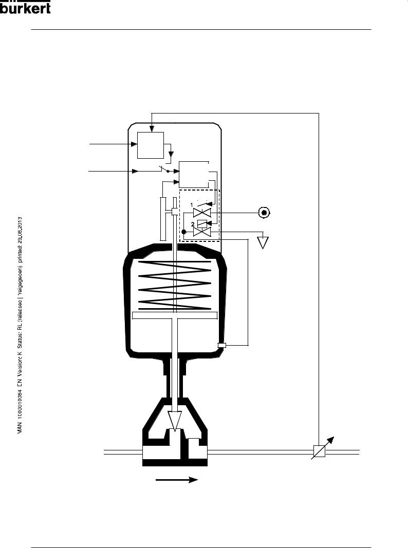
Fuctional diagram as a positioner with single-acting actuator
Actual process value
Process |
|
|
|
setpoint |
Process |
Setpoint position |
|
external |
controller |
|
|
|
|
|
|
position |
|
|
|
setpoint |
|
Positioner |
|
|
|
Positioning system |
|
|
|
|
|
|
Actual |
|
1: pressurizing valve |
|
|
2: exhaust valve |
|
|
position |
|
|
|
Positioning |
|
|
|
|
|
|
TOP Control Continuous |
|
system |
|
|
Position |
|
Compressed air |
|
|
supply |
|
|
sensor |
|
|
|
|
|
|
|
|
|
Exhaust air |
Pneumatic |
|
|
|
actuator |
|
|
|
(single-acting) |
|
|
|
Valve |
|
|
|
(actuator) |
|
|
|
|
|
|
Sensor |
Actual process value (flow rate, pressure, level,
 temperature
 etc.)
etc.)
18 - 8630
SYSTEM DESCRIPTION
Operating as a positioner
The actual position (POS) of the pneumatic actuator is measured via the position sensing system. The controller compares this actual value of the position with the setpoint (CMD) , which can be specified as a standard signal. If a control difference (Xd1) exists, a pulse-width modulated voltage signal is sent to the positioning system as the correcting variable. With single-acting actuators, if the difference is positive, the pressurizing valve is driven via output B1; if it is negative, the exhaust valve is driven via output E1. In this way, the position of the actuator is altered until the control difference is zero. Z1 represents a disturbance.
|
|
|
Z1 |
|
|
B1 |
|
CMD |
Xd1 |
PK |
Valve opening |
|
|||
|
|
E1 |
|
Position setpoint |
Positioner |
Positioning |
Continious valve |
|
|
system Sole- |
|
|
|
noid |
|
|
|
POS |
|
|
Position control |
PositionWegmeßsystemsensor |
|
|
loop |
|
|
|
|
|
8630 - 19

SYSTEM DESCRIPTION
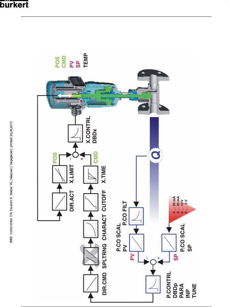
Schematicrepresentationofpositioningcontrol
CMD
POS
POS
 X.LIMIT
 DIR.ACT
20mA |
20mA |
10V |
5V |
4… |
0… |
0… |
0… |
INP
X.CONTRL |
DBDx |
|
CMD |
|
X.TIME |
|
CUTOFF |
|
CHARACT |
|
SPLTRNG |
INP |
DIR.CMD |
20 - 8630

|
|
|
SYSTEM DESCRIPTION |
|
Characteristics of the positioner software |
||||
|
|
|
|
|
|
|
Supplementary function |
Effect |
|
|
|
|
|
|
|
|
Positioner with supplementary functions |
|
|
|
|
|
|
|
|
|
|
Valve closes tight outside control range. A value is |
|
|
|
Tight-closing function |
given (at %) from which the actuator is completely |
|
|
|
|
exhausted (at 0%) or pressurized (at 100 %). |
|
|
|
|
|
|
|
|
Stroke limitation |
Mech. valve piston movement only withhin a specified |
|
|
|
stroke range. |
|
|
|
|
|
|
|
|
|
|
|
|
|
|
Signal range splitting |
Splitting of the standard signal range over two or more |
|
|
|
TOP Control Continuous. |
|
|
|
|
|
|
|
|
|
|
|
|
|
|
Correction characteristic to match |
Linearization of the process characteristic can be |
|
|
|
the operating curve |
performed. |
|
|
|
|
|
|
|
|
Insensitivity range |
The positioner cuts in only above a specified control |
|
|
|
difference. |
|
|
|
|
|
|
|
|
|
|
|
|
|
|
Direction of action of the controller |
Reversal of the setpoint action direction |
|
|
|
setpoint |
|
|
|
|
|
|
|
|
|
|
|
|
|
|
Safety position |
Valve moves to a specified safety position. |
|
|
|
|
|
|
Hierarchical concept for simple operation with the following levels
Process operation
In this level your switch between automatic and manual operation.
In this level you specify on commissioning certain basic Configuration functions and configure supplementary functions as
needed.
8630 - 21

SYSTEM DESCRIPTION
* Operation as a process controller (option)
On operation of the TOP Control Continuous as a process controller, the abovementioned position control becomes a subordinate auxiliary control loop; the result is a cascade control. The process controller in the main loop of the TOP Control Continuous has a PID function. The setpoint specified is the process setpoint (SP) and it is compared with the process variable to be controlled. The actual position (XPOS) of the pneumatic actuator is measured via the position sensing system. The controller compares this actual value of the position with the setpoint (CMD) , which can be specified as a standard signal. If a control difference (Xd1) exists, a pulse-width modulated voltage signal is sent to the positioning system as the correcting variable. With single-acting actuators, if the difference is positive, the pressurizing valve is driven via output B1. If it is negative, the exhaust valve is driven via output E1. In this way, the position of the actuator is altered until the control difference is zero. Z2 represents a disturbance.
|
|
Z1 |
|
|
B1 |
|
|
Xd1 |
PK |
|
|
|
E1 |
|
Valve |
|
|
|
|
Positioner |
Positioning |
Continuous |
opening |
|
|||
|
system Soleno- |
Valve |
|
|
id valves |
|
|
|
XPOS |
|
|
|
Position sensor |
|
|
Position control loop |
|
|
|
|
|
|
|
|
Z2 |
|
|
|
|
Process |
Valve |
|
|
SP |
Xd2 |
CMD |
opening |
Process variable |
||
control |
||||||
|
|
|
|
|
||
|
|
|
loop |
|
|
Process Process controller 


 Process setpoint


 PV
PV
Transmitter
Example of process control:
TOP Control Continuous with sensor
22 - 8630
SYSTEM DESCRIPTION
Schematicrepresentationofprocesscontrol
8630 - 23

SYSTEM DESCRIPTION
Characteristics of the process controller software
Supplementary function |
Effect |
|
|
|
|
Positioner with supplementary functions |
||
|
|
|
|
Valve closes tight outside control range. A value is |
|
Tight-closing function |
given (at %) from which the actuator is completely |
|
|
exhausted (at 0%) or pressurized (at 100%). |
|
Stroke limitation |
Mech. valve piston movement only within a specified |
|
stroke range. |
||
|
||
Signal range splitting |
Splitting of the standard signal range over two or more |
|
TOP Control Continuous. |
||
|
||
|
|
|
Correction characteristic to match |
Linearization of the process characteristic can be |
|
the operating curve |
performed. |
|
|
|
|
Insensitivity range |
The positioner cuts in only after a specified control |
|
difference. |
||
|
||
|
|
|
Direction of action of the controller |
Reserval of the setpoint action direction |
|
setpoint |
||
|
||
|
|
|
Safety position |
Valve moves to a specified safety position |
|
|
|
|
Analog feedback (option) |
Feedback of the position/process values |
|
Binary outputs |
||
|
||
|
|
|
|
|
|
Connectable process controller with the following characteristics (Option) |
||
|
|
|
Controller structure |
PID |
|
|
|
|
Parameters that can be set |
Proportional action factor, reset time, rate time and |
|
operating point |
||
|
||
Scalable input |
Decimal point position, upper and lower sacle valures |
|
of process value and setpoint |
||
|
||
Method of setpoint setting |
Setting either via standard signal input or via keys |
|
|
|
|
Hierarchical concept for simple operation with the following levels
Process operation
In this level your switch between automatic and manual operation.
In this level you specify on commissioning certain basic Configuration functions and configure supplementary functions as
needed.
24 - 8630

SYSTEM DESCRIPTION
* Operation as a flow rate controller (option)
The flow rate controller is a special type of process controller. The process value (PV) is not measured directly via an analog input but calculated in the device by the dp method. According to the algorithm, the flow rate is dependent on the parameters pressure before valve (p1), pressure after valve (p2), medium temperature (T) and the kv value. For this reason, the TOP Control Continuous FMR has inputs for 2 pressure transmitters and a temperature transmitter which can be optionally connected.
One pressure transmitter measures the pressure before the valve and a second one after the valve. The temperature is either entered manually in the operating menu or is provided as a standard signal by a temperature transmitter. The kv value is determined internally from the current position of the control valve. For this purpose, a kv characteristic curve is provided in the control valve used.
The density of the medium is entered via the operating menu.
Temperature (optional)
Pressure |
Pressure |
p1 |
PV |
p2 |
8630 Flowrate controller
|
e.g.valve |
|
|
type |
2712 |
T |
kv value |
|
|
|
|
p1 |
|
p2 |
In the case of the flow rate controller, the process parameters are either the volumetric flow rate or, for special applications, the transport velocity at the end of a pumping section.
The volumetric flow rate is represented in m3/h STP, i.e. referred to 0 °C (medium temperature) and a gas pressure of 1013 mbar (abs).
There are special applications for flow rate controllers in which a pumping section is set up after the valve, in which bulk goods enter via an airlock. These bulk goods are blown through the pumping section by the pumping pressure that builds up behind the valve.
The transport velocity corresponds to the volumetric flow rate of the medium, referred to the piping diameter of the pumping section. However, it is not specified for standard conditions, but reflects the velocity of the gas particles at the existing medium temperature. The diameter is entered in the operating menu.
Characteristics of the flow rate controller software
The flow rate controller offers the same functions as the process controller.
8630 - 25

SYSTEM DESCRIPTION
Schematicrepresentationofprocesscontrolwithflowratecontroller
26 - 8630
SYSTEM DESCRIPTION
*Interfaces of theTOP Control Continuous in the multipole variant
Inputs for position or process setpoint
4..20 mA
0..20 mA 0..10 V
0..5 V
Input for process setpoint
4..20 mA
Frequency Pt 100
* Flow rate controller
Binary input
24 V DC
Inputs
Supply
TOPControl |
Outputs |
|
|
Continuous |
|
(multipole - variant)
Operating unit
2 binary outputs
Analog position feedback
*Initiators 1 + 2
* Note:
Inputs for process value with flow rate controller (option): p1, p2, T (optional).
The standard process controller inputs (4 ... 20 mA, frequency, Pt 100) and the initiators cannot be used with this option.
NOTE |
|
TOP Control Continuous Type 8630 is a 3-conductor device, i.e. the voltage supply (24 V |
|
|
DC) is separate from the setpoint signal. |
8630 - 27
SYSTEM DESCRIPTION
*Interface of theTOP Control Continuous in the variants with cable bushings
Inputs for position or process setpoint
4..20 mA 0..20 mA 0..10 V 0..5 V
Input for process setpoint* 4..20 mA
Frequency Pt 100
(alternative to binary outputs)
Binary input
24 V DC
Inputs
Supply
TOPControl Continuous
(PG - variant)
Operating unit
Outputs
2 binary outputs*
(alternative to input for process setpoint)
Analog
position feedback
* Note:
The choice between a process setpoint input and two binary outputs is made by positioning the jumper.
NOTE |
|
TOP Control Continuous Type 8630 is a 3-conductor device, i.e. the voltage supply (24 V |
|
|
DC) is separate from the setpoint signal. |
28 - 8630
 Loading...