


 Loading...
Type 8694
Positioner Top Control Basic
Electropneumatic position controller
Operating Instructions

We reserve the right to make technical changes without notice. Technische Änderungen vorbehalten.
Sous réserve de modifications techniques.
© Bürkert Werke GmbH & Co. KG, 2008 - 2019
Operating Instructions 1909/10_EN-EN_00805886 / Original DE
Type 8694
Positioner Type 8694
Table of Contents
1 |
OPERATING INSTRUCTIONS........................................................................................................................................................ |
7 |
||
|
1.1 |
Symbols....................................................................................................................................................................................... |
|
7 |
|
1.2 |
Definition of term / abbreviation.................................................................................................................................... |
7 |
|
2 |
AUTHORIZED USE.............................................................................................................................................................................. |
8 |
||
|
2.1 |
Restrictions................................................................................................................................................................................ |
8 |
|
3 |
BASIC SAFETY INSTRUCTIONS.................................................................................................................................................. |
9 |
||
4 |
GENERAL INFORMATION............................................................................................................................................................. |
10 |
||
|
4.1 |
Contact address................................................................................................................................................................... |
10 |
|
|
4.2 |
Warranty.................................................................................................................................................................................... |
|
10 |
|
4.3 |
Trademarks............................................................................................................................................................................. |
10 |
|
|
4.4 |
Information on the internet............................................................................................................................................ |
10 |
|
5 |
SYSTEM DESCRIPTION................................................................................................................................................................. |
11 |
||
|
5.1 |
Intended application area............................................................................................................................................... |
11 |
|
|
5.2 |
Function of the positioner and combination with valve types.................................................................... |
11 |
|
|
5.3 |
Features of the valve types............................................................................................................................................ |
12 |
|
|
5.4 |
Structure of the positioner............................................................................................................................................. |
13 |
|
|
|
5.4.1 |
Representation.................................................................................................................................... |
13 |
|
|
5.4.2 |
Features................................................................................................................................................ |
14 |
|
|
5.4.3 |
Function diagram of the positioner with single-acting actuator............................................... |
15 |
|
5.5 |
Type 8694 positioner (position controller)............................................................................................................. |
16 |
|
|
|
5.5.1 |
Schematic representation of the position control Type 8694.................................................. |
16 |
|
|
5.5.2 |
Functions of the position controller software............................................................................... |
17 |
|
5.6 |
Interfaces of the positioner .......................................................................................................................................... |
19 |
|
6 |
TECHNICAL DATA............................................................................................................................................................................. |
20 |
||
|
6.1 |
Conformity............................................................................................................................................................................... |
20 |
|
|
6.2 |
Standards................................................................................................................................................................................ |
20 |
|
|
6.3 |
Licenses................................................................................................................................................................................... |
|
20 |
|
6.4 |
Operating conditions......................................................................................................................................................... |
20 |
|
3
english

Type 8694
|
6.5 |
Mechanical data................................................................................................................................................................... |
20 |
|
|
6.6 |
Pneumatic data..................................................................................................................................................................... |
21 |
|
|
6.7 |
Type labels.............................................................................................................................................................................. |
21 |
|
|
|
6.7.1 |
Type label standard............................................................................................................................ |
21 |
|
|
6.7.2 |
UL type label........................................................................................................................................ |
22 |
|
|
6.7.3 |
UL additional label.............................................................................................................................. |
22 |
|
6.8 |
Electrical data........................................................................................................................................................................ |
22 |
|
|
|
6.8.1 |
Electrical data without bus control 24 V DC................................................................................ |
22 |
|
|
6.8.2 |
Electrical data with AS-Interface bus control............................................................................... |
23 |
|
6.9 |
Factory settings of the positioner.............................................................................................................................. |
24 |
|
7 |
CONTROL AND DISPLAY ELEMENTS.................................................................................................................................... |
25 |
||
|
7.1 |
Operating status...................................................................................................................................................................... |
25 |
|
|
7.2 |
Control and display elements of the positioner................................................................................................. |
25 |
|
|
7.3 |
Configuration of the keys................................................................................................................................................... |
27 |
|
|
7.4 |
Function of the DIP switches........................................................................................................................................... |
29 |
|
|
7.5 |
Display of the LEDs................................................................................................................................................................ |
31 |
|
|
7.6 |
Error messages........................................................................................................................................................................ |
32 |
|
|
|
7.6.1 |
Error messages in MANUAL and AUTOMATIC operating statuses.......................................... |
32 |
|
|
7.6.2 |
Error messages while the X.TUNE function is running ............................................................... |
32 |
8 |
INSTALLATION.................................................................................................................................................................................... |
|
33 |
|
|
8.1 |
Safety instructions.............................................................................................................................................................. |
33 |
|
|
8.2 |
Installation of the positioner Type 8694 on process valves of series 2103, 2300 and 2301..... |
33 |
|
|
8.3 |
Installing the positioner Type 8694 on process valves belonging to series 26xx and 27xx........... |
36 |
|
|
8.4 |
Rotating the actuator module....................................................................................................................................... |
40 |
|
|
8.5 |
Rotating the positioner for process valves belonging to series 26xx and 27xx............................... |
42 |
|
9 |
PNEUMATIC INSTALLATION....................................................................................................................................................... |
43 |
||
|
9.1 |
Manual actuation of the actuator via pilot valves.............................................................................................. |
44 |
|
|
|
9.1.1 |
Single-acting actuators (control function A and B).................................................................... |
44 |
10 |
ELECTRICAL INSTALLATION 24 V DC................................................................................................................................... |
46 |
||
|
10.1 |
Safety instructions.............................................................................................................................................................. |
46 |
|
4
english

Type 8694
|
10.2 |
Electrical installation with circular plug-in connector...................................................................................... |
46 |
|
|
|
10.2.1 Designation of the contacts Type 8694........................................................................................ |
46 |
|
|
|
10.2.2 Connection of the positioner Type 8694...................................................................................... |
47 |
|
|
10.3 |
Electrical installation with cable gland.................................................................................................................... |
48 |
|
11 |
AS-INTERFACE INSTALLATION................................................................................................................................................. |
51 |
||
|
11.1 |
AS-Interface connection.................................................................................................................................................. |
51 |
|
|
11.2 |
Maximum length of the bus line.................................................................................................................................. |
51 |
|
|
11.3 |
Technical data for AS-Interface PCBs...................................................................................................................... |
51 |
|
|
11.4 |
Programming data.............................................................................................................................................................. |
52 |
|
|
11.5 |
Communication sequence for the version S-7.A.5 profile ........................................................................... |
53 |
|
|
11.6 |
LED status display.............................................................................................................................................................. |
54 |
|
|
11.7 |
Electrical installation AS-interface............................................................................................................................. |
55 |
|
|
|
11.7.1 |
Safety instructions.............................................................................................................................. |
55 |
|
|
11.7.2 Connection with circular plug-in connector M12 x 1, 4-pole, male........................................ |
56 |
|
|
|
11.7.3 Connection with multi-pole cable and ribbon cable terminal................................................... |
56 |
|
12 |
START-UP.............................................................................................................................................................................................. |
|
58 |
|
|
12.1 |
Safety instructions.............................................................................................................................................................. |
58 |
|
|
12.2 |
Specifying the standard settings................................................................................................................................ |
58 |
|
|
|
12.2.1 Running the automatic adjustment X.TUNE.......................................................................... |
58 |
|
13 |
OPERATION AND FUNCTION..................................................................................................................................................... |
61 |
||
|
13.1 |
Basic functions......................................................................................................................................................................... |
61 |
|
|
|
13.1.1 |
DIR.CMD - |
|
|
|
|
Effective direction of the positioner set-point value.................................................................... |
62 |
|
|
13.1.2 |
CUTOFF - |
|
|
|
|
Sealing function for the positioner.................................................................................................. |
63 |
13.1.3CHARACT -
Select the transfer characteristic between input signal (position set-point value) and
stroke..................................................................................................................................................... |
64 |
13.1.4 INPUT - |
|
Enter the input signal......................................................................................................................... |
66 |
13.1.5RESET -
|
Reset to factory settings................................................................................................................... |
67 |
13.1.6 |
X.TUNE - |
|
|
Automatic adjustment of the positioner to the relevant operating conditions...................... |
67 |
5
english

Type 8694
|
13.2 |
Auxiliary functions.................................................................................................................................................................. |
68 |
|
|
|
13.2.1 |
DIR.ACTUATOR - |
|
|
|
|
Effective direction of the actuator................................................................................................... |
68 |
|
|
13.2.2 |
SPLITRANGE - |
|
|
|
|
Signal split range................................................................................................................................ |
69 |
|
|
13.2.3 |
X.LIMIT - |
|
|
|
|
Limiting the mechanical stroke range............................................................................................. |
70 |
|
|
13.2.4 |
X.TIME - |
|
|
|
|
Limiting the control speed................................................................................................................ |
71 |
|
|
13.2.5 |
X.CONTROL - |
|
|
|
|
Parameterization of the positioner................................................................................................... |
72 |
|
|
13.2.6 |
SAFE POSITION - |
|
|
|
|
Definition of the safe position........................................................................................................... |
72 |
|
|
13.2.7 |
SIGNAL ERROR - |
|
|
|
|
Configuration of signal level fault detection.................................................................................. |
73 |
|
|
13.2.8 |
BINARY INPUT - |
|
|
|
|
Activation of the binary input............................................................................................................ |
73 |
|
|
13.2.9 |
OUTPUT (optional) - |
|
|
|
|
Configuration of the analog output................................................................................................. |
74 |
14 |
SAFETY END POSITIONS............................................................................................................................................................ |
75 |
||
|
14.1 |
Safety end positions after failure of the electrical or pneumatic auxiliary power........................... |
75 |
|
15 |
MAINTENANCE................................................................................................................................................................................... |
|
76 |
|
|
15.1 |
Safety instructions.............................................................................................................................................................. |
76 |
|
|
15.2 |
Service at the air intake filter........................................................................................................................................ |
77 |
|
16 |
ACCESSORIES................................................................................................................................................................................... |
|
78 |
|
|
16.1 |
Communications software............................................................................................................................................. |
78 |
|
|
|
16.1.1 |
USB interface...................................................................................................................................... |
78 |
|
|
16.1.2 |
Download.............................................................................................................................................. |
78 |
17 |
DISASSEMBLY.................................................................................................................................................................................... |
|
79 |
|
|
17.1 |
Safety instructions.............................................................................................................................................................. |
79 |
|
|
17.2 |
Disassembly the positioner........................................................................................................................................... |
79 |
|
18 |
PACKAGING AND TRANSPORT................................................................................................................................................ |
81 |
||
19 |
STORAGE.............................................................................................................................................................................................. |
|
81 |
|
20 |
DISPOSAL............................................................................................................................................................................................. |
|
81 |
|
6
english
Type 8694
Operating instructions
1OPERATING INSTRUCTIONS
The operating instructions describe the entire life cycle of the device. Keep these instructions in a location which is easily accessible to every user, and make these instructions available to every new owner of the device.
Important safety information.
Read the operating instruction carefully and thoroughly. Study in particular the chapters entitled “Basic safety instructions” and “Authorized use”.
The operating instructions must be read and understood.
1.1Symbols
 DANGER!
Warns of an immediate danger.
Failure to observe the warning will result in a fatal or serious injury.
 WARNING!
Warns of a potentially dangerous situation.
Failure to observe the warning may result in serious injuries or death.
 CAUTION!
Warns of a possible danger.
Failure to observe this warning may result in a moderate or minor injury.
NOTE!
Warns of damage to property.
• Failure to observe the warning may result in damage to the device or the equipment.
 Indicates important additional information, tips and recommendations.
 refers to information in these operating instructions or in other documentation.
Designates an instruction to prevent risks. →→Designates a procedure which you must carry out.
1.2Definition of term / abbreviation
The term “device” used in these instructions always stands for the positioner Type 8694.
In these instructions, the abbreviation “Ex” always refers to “potentially explosive”.
7
english
Type 8694
Authorized use
2AUTHORIZED USE
Non-authorized use of the positioner Type 8694 may be a hazard to people, nearby equipment and the environment.
The device is designed to be mounted on pneumatic actuators of process valves for the control of media.Do not expose the device to direct sunlight.
Use according to the authorized data, operating conditions and conditions of use specified in the contract documents and operating instructions. These are described in the chapter entitled “6 Technical data”.
The device may be used only in conjunction with third-party devices and components recommended and authorized by Bürkert.
In view of the large number of options for use, before installation, it is essential to study and if necessary to test whether the positioner is suitable for the actual use planned.
Correct transportation, correct storage and installation and careful use and maintenance are essential for reliable and faultless operation.
Use the positioner Type 8694 only as intended.
2.1 Restrictions
If exporting the system/device, observe any existing restrictions.
8
english
Type 8694
Basic safety instructions
3BASIC SAFETY INSTRUCTIONS
These safety instructions do not make allowance for any
•contingencies and events which may arise during the installation, operation and maintenance of the devices.
•local safety regulations – the operator is responsible for observing these regulations, also with reference to the installation personnel.
 DANGER!
Risk of injury from high pressure in the equipment/device.
Before working on equipment or device, switch off the pressure and deaerate/drain lines.
Risk of electric shock.
Before working on equipment or device, switch off the power supply and secure to prevent reactivation.Observe applicable accident prevention and safety regulations for electrical equipment.
General hazardous situations.
To prevent injury, ensure:
In the potentially explosion-risk area the positioner Type 8694 may be used only according to the specification on the separate approval sticker. For use observe the additional instructions enclosed with the device together with safety instructions for the explosion-risk area.
Devices without a separate approval sticker may not be used in a potentially explosive area.That the system cannot be activated unintentionally.
Installation and repair work may be carried out by authorized technicians only and with the appropriate tools.
After an interruption in the power supply or pneumatic supply, ensure that the process is restarted in a defined or controlled manner.
The device may be operated only when in perfect condition and in consideration of the operating instructions.The general rules of technology apply to application planning and operation of the device.
To prevent damage to property on the device, ensure:
Do not feed any aggressive or flammable media into the pilot air port.Do not feed any liquids into the pilot air port.
When unscrewing and screwing in the body casing or the transparent cap, do not hold the actuator of the process valve but the connection housing of Type 8694.
Do not put any loads on the housing (e.g. by placing objects on it or standing on it).
Do not make any external modifications to the device bodies. Do not paint the housing parts or screws.
9
english
Type 8694
Basic safety instructions
NOTE!
Electrostatic sensitive components / modules.
The device contains electronic components, which react sensitively to electrostatic discharge (ESD). Contact with electrostatically charged persons or objects is hazardous to these components. In the worst case scenario, they will be destroyed immediately or will fail after start-up.
Observe the requirements in accordance with EN 100 015 - 1 and to minimize or avoid the possibility of damage caused by sudden electrostatic discharge.
Also ensure that you do not touch electronic components when the power supply is on.
4GENERAL INFORMATION
4.1 Contact address
Germany
Bürkert Fluid Control System
Sales Center
Chr.-Bürkert-Str. 13-17
D-74653 Ingelfingen
Tel. + 49 (0) 7940 - 10 91 111
Fax + 49 (0) 7940 - 10 91 448
E-mail: info@burkert.com
International
Contact addresses can be found on the final pages of the printed operating instructions.
And also on the Internet at:
www.burkert.com
4.2 Warranty
The warranty is only valid if the positioner Type 8694 is used as intended in accordance with the specified application conditions.
4.3 Trademarks
Brands and trademarks listed below are trademarks of the corresponding companies / associations / organizations Loctite Henkel Loctite Deutschland GmbH
4.4Information on the internet
The operating instructions and data sheets for Type 8694 can be found on the Internet at:
www.burkert.com
10
english
Type 8694
System description
5SYSTEM DESCRIPTION
5.1Intended application area
The positioner Type 8694 is designed to be mounted on pneumatic actuators of process valves for the control of media.
5.2Function of the positioner and combination with valve types
Positioner Type 8694 is an electropneumatic position controller for pneumatically actuated control valves with single-acting actuators.
Together with the pneumatic actuator, the positioner forms a functional unit.
The control valve systems can be used for a wide range of control tasks in fluid technology and, depending on the application conditions, different process valves belonging to series 2103, 2300, 2301, 26xx or 27xx from the Bürkert range can be combined with the positioner. Angle-seat valves, diaphragm valves or ball valves fitted with a control cone are suitable.
“Figure 1” shows an overview of the possible combinations of positioner and different pneumatically actuated valves. Different actuator sizes and valve nominal widths, not illustrated here, are available for each type. More precise specifications can be found on the respective data sheets. The product range is being continuously expanded.
Positioner Type 8694
with diaphragm valve
Type 2730
with angle seat valve |
with straight seat valve |
with angle seat valve |
|
 Type 2300 |
Type 2301 |
Type 2702 |
|
|
|
|
|
Figure 1: |
Overview of possible combinations |
|
|
11
english
Type 8694
System description
The position of the actuator is regulated according to the position set-point value. The position set-point value is specified by an external standard signal.
Pneumatically actuated piston actuators and rotary actuators can be used as an actuator. Single-acting actuators are offered in combination with the positioner.
For single-acting actuators, only one chamber is aerated and deaerated in the actuator. The generated pressure works against a spring. The piston moves until there is an equilibrium of forces between compressive force and spring force.
5.3Features of the valve types
|
Angle seat control |
Diaphragm valves |
Ball valves |
Flap valves |
||||
|
valves / straight seat |
|
|
|
|
|
|
|
|
control valves |
|
|
|
|
|
|
|
|
|
|
|
|
||||
Types |
• 2300 |
• 2103 |
• 2652 |
• 2672 |
||||
|
• 2301 |
• 2730 |
• 2655 |
• 2675 |
||||
|
• 2702 |
• 2731 |
• 2658 |
|
|
|||
|
• 2712 |
|
|
|
|
|
|
|
|
|
|
|
|
|
|
|
|
Features |
• |
incoming flow under |
• |
medium is hermeti- |
• |
scrapable |
• |
unaffected by |
|
|
seat |
|
cally separated from |
• minimum dead space |
|
contamination |
|
|
|
|
|
the actuator and |
|
|
||
|
• |
no closing impact |
|
|
|
• |
little pressure |
|
|
|
environment |
• |
unaffected by |
||||
|
|
|
|
|
loss compared to |
|||
|
|
|
|
|
|
|||
|
• |
straight flow path of |
|
|
|
contamination |
|
|
|
• |
cavity-free and self- |
|
|
other valve types |
|||
|
|
the medium |
|
|
|
|||
|
|
|
draining body design |
• |
little pressure loss |
|
|
|
|
|
|
|
• |
inexpensive |
|||
|
|
|
|
|
||||
|
• |
self-adjusting |
|
|
|
compared to other |
||
|
• |
any flow direction with |
|
|
|
|||
|
|
stuffing box for high |
|
valve types |
• |
low construction |
||
|
|
|
low-turbulence flow |
|
||||
|
|
leak-tightness |
|
|
|
|
volume |
|
|
|
|
|
• |
seat and seal can |
|
||
|
|
|
• |
steam-sterilizable |
|
|
||
|
|
|
|
be exchanged in the |
|
|
||
|
|
|
|
|
|
|
|
|
|
|
|
• |
CIP-compliant |
|
three-piece ball valve |
|
|
|
|
|
• |
no closing impact |
|
when installed |
|
|
|
|
|
|
|
|
|
||
|
|
|
• |
actuator and dia- |
Note |
|
|
|
|
|
|
|
phragm can be |
can be used as |
|
|
|
|
|
|
|
removed when the |
process controller only |
|
|
|
|
|
|
|
body is installed |
|
|
|
|
Typical |
• |
water, steam and |
• |
neutral gases and |
• |
neutral gases and |
• |
neutral gases |
media |
|
gases |
|
liquids |
|
liquids |
|
and liquids |
|
• |
alcohols, oils, propel- |
• |
contaminated, |
• |
clean water |
• |
slightly |
|
|
lants, hydraulic fluids |
|
abrasive and |
• |
slightly aggressive |
|
aggressive media |
|
|
|
|
aggressive media |
|
|
||
|
• |
salt solutions, lyes |
|
|
media |
|
|
|
|
|
|
|
|
|
|||
|
|
(organic) |
• |
media of higher |
|
|
|
|
|
• |
solvents |
|
viscosity |
|
|
|
|
|
|
|
|
|
|
|
||
Table 1: |
Features of the valve types |
|
|
|
|
|
|
|
12
english

Type 8694
System description
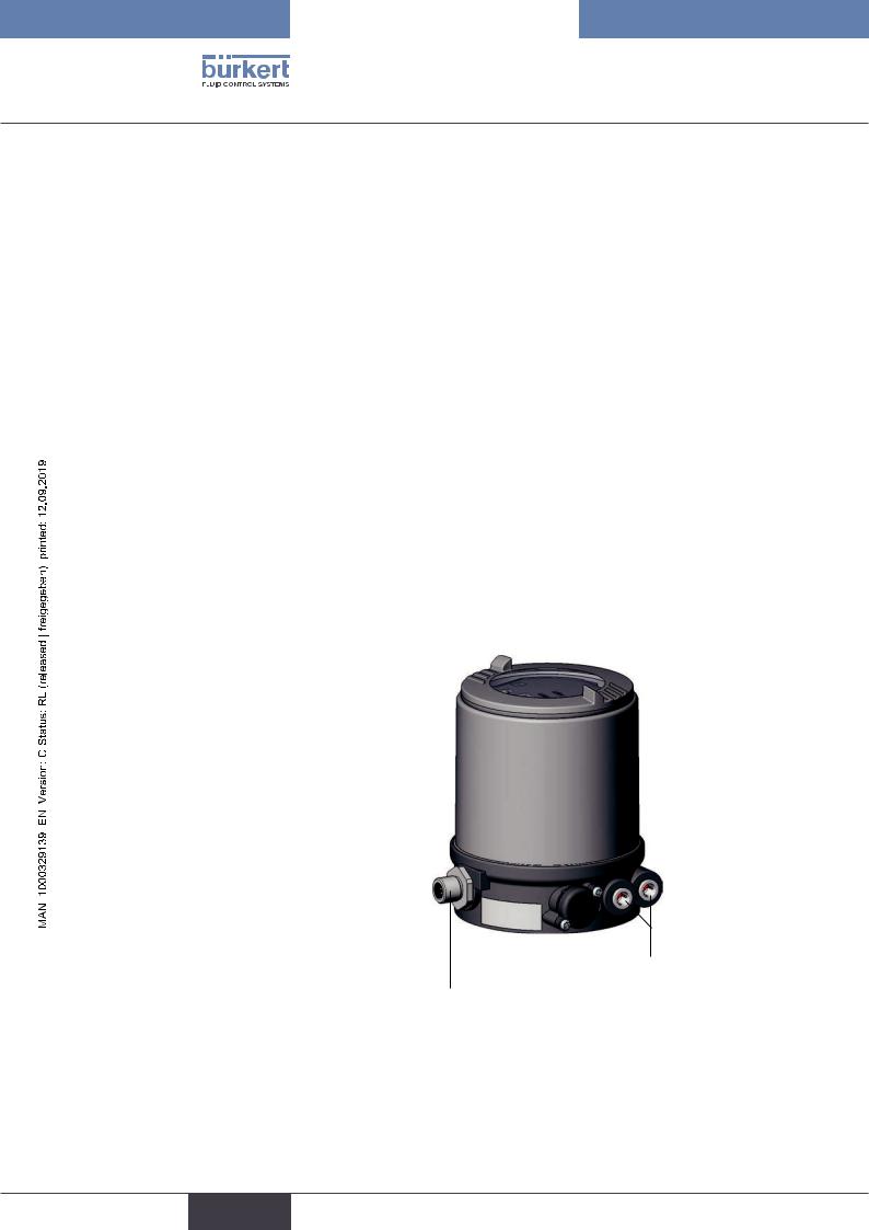
5.4Structure of the positioner
The positioner Type 8694 consists of the micro-processor controlled electronics, the position measuring system and the control system. The device is designed using three-wire technology. The positioner is operated via 2 keys and a 4-pole DIP switch. The pneumatic control system for single-acting actuators consists of 2 solenoid valves.
5.4.1Representation
Version 1 |
Version 2 |
Transparent cap
Body casing
Pressure limiting valve (for protection against too high internal pressure in case of error)
Connection housing
Exhaust air connection (label: 3)
Body casing removed:
Air intake filter (exchangeable)
Pressure supply connection |
Exhaust air con- |
Pressure supply |
||||
(label: 1) |
nection (label: 3) |
connection (label: 1) |
||||
|
|
Buttons |
|
Communications |
||
LED |
|
interface |
||||
|
|
|
|
|
|
LED |
|
|
DIP Switches |
|
|
|
|
|
|
Communications |
|
|
|
Screw- |
|
|
|
|
|
||
|
|
|
||||
|
|
interface |
|
|
|
type |
|
|
|
|
|
|
terminals |
Air intake filter
(exchangeable)
Electrical connection (cable gland M16 x 1.5
or circular plug-in connector M12 x 1)
Additional exhaust air port (label: 3.1) only for Type 23xx and 2103 with pilot-operated control system for high air flow rate (actuator size ø 130)
Figure 2: |
Structure |
|
13 |
english
Type 8694
System description
5.4.2Features
•Models
for single-acting valve actuators.
•Position measuring system
Contactless and therefore wear-free position measuring system.
•Microprocessor-controlled electronics for signal processing, control and valve control.
•Control module
The device is controlled via 2 buttons and a 4-pole DIP switch. 2x 2-colored LEDs indicate different statuses of the device.
•Control system
The control system consists of 2 solenoid valves. One valve is used to aerate and another to deaerate the pneumatic actuator. The solenoid valves operate according to the rocker principle and are controlled with a
PWM voltage via the controller. Doing so achieves a higher flexibility with regard to actuator volume and final control speed. The direct-action model has an orifice of DN 0.6. In larger pneumatic actuators the solenoid valves feature diaphragm amplifiers to increase the maximum flow and therefore to improve the dynamics (DN 2.5).
• Position feedback (optional)
The position of the valve can be transmitted to the PLC via an analog 0/4-20 mA output.
• Binary input
If a voltage > 10 V is applied, SAFE POSITION is activated, i.e. the valve is moved to the safety position (factory setting, can be changed with communications software).
• Pneumatic interfaces
1/4“ connections with different thread forms (G, NPT)
hose plug-in connection
• Electrical interfaces
Circular plug-in connector or cable gland
Pneumatic interface
 |
Electrical interface |
|
•Body
The body of the positioner is protected from excessively high internal pressure, e.g. due to leaks, by a pressure limiting valve.
•Communications interface
14 |
For configuration and parameterization. |
|
english
Type 8694
System description
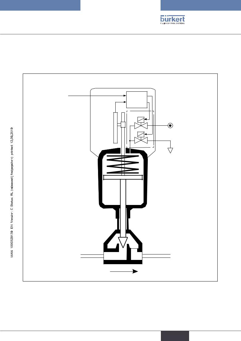
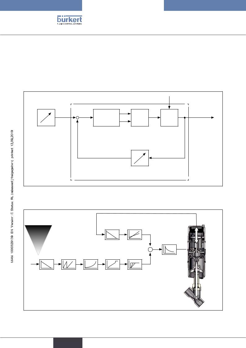
5.4.3Function diagram of the positioner with single-acting actuator
The illustrated function diagram describes the function of the positioner (Type 8694).
external |
|
|
|
position |
|
|
|
set-point value |
|
Position |
|
|
|
|
|
|
Actual |
controller |
|
Positioner |
|
Control system |
|
position |
|
||
|
Control system |
1: Aeration valve |
|
|
|
||
|
|
1 |
2: Bleed valve |
|
|
|
|
|
Position |
|
Pressure |
|
|
supply |
|
|
measuring |
2 |
|
|
|
||
|
system |
|
|
|
|
|
Exhaust air |
Pneumatic actuator (single-acting)
Valve (actuator)

Figure 3: Function diagram
15
english
Type 8694
System description
5.5Type 8694 positioner (position controller)
The position measuring system records the current position (POS) of the pneumatic actuator. The position controller compares this actual position value with the set-point value (CMD) which is definable as standard signal. In case of a control deviation (Xd1), a pulse-width modulated voltage signal is sent to the control system as a manipulated variable. If there is a positive control difference in single-acting actuators, the air inlet valve is controlled via output B1. If the control difference is negative, the bleed valve is controlled via output E1. In this way the position of the actuator is changed until control difference is 0. Z1 represents a disturbance variable.
|
|
|
Z1 |
|
|
B1 |
|
CMD |
Xd1 |
PK |
Valve opening |
+ |
- |
E1 |
|
|
|
||
Position |
Position |
Control system |
Control valve |
set-point |
controller |
Solenoid valves |
|
value |
|
|
|
|
|
POS |
|
|
Position control |
Position measuring system |
|
|
circuit |
||
 |
|
|
|
|
|
|
|
Figure 4: Signal flow plan of position controller
5.5.1 Schematic representation of the position control Type 8694
|
|
|
|
POS |
|
|
4 ... 20 mA1) |
|
|
|
|
|
0 ... 20 mA |
|
DIR.ACT2) |
X.LIMIT2) |
POS |
|
|
|
|
|
CMD |
INP |
|
|
|
X.CONTROL |
|
|
|
|
|
||
|
|
|
|
CMD |
DBND |
|
DIR.CMD SPLTRNG2) |
CHARACT |
CUTOFF |
X.TIME2) |
|
1) |
Default setting |
|
|
|
|
2) Can only be activated with communications software |
|
|
|||
Figure 5: Schematic representation of position control
16
english
Type 8694
System description
5.5.2Functions of the position controller software
Functions I |
|
|
|
|
|
|
|
• |
Activation via DIP switches |
|
|
|
|
|
|
• |
Parameter setting via communications software |
|
|
|
|
|
|
|
|
|
|
|
|
|
|
|
Additional function |
Effect |
|||||
|
|
|
|
|
|
|
|
|
Sealing function |
Valve closes tight outside the control range. Specification |
|||||
|
of the value (as %), from which the actuator is completely |
||||||
|
CUTOFF |
|
deaerated (when 0 %) or aerated (when 100 %) |
||||
|
|
|
(see chapter “7.4 Function of the DIP switches”). |
||||
|
|
|
|
|
|
|
|
|
Correction line to adjust the operating characteristic |
Linearization of the operating characteristic can be imple- |
|||||
|
CHARACT |
|
mented (see chapter |
“7.4 Function of the DIP switches”) |
. |
||
|
|
|
|||||
|
|
|
|
|
|
|
|
|
Effective direction of the controller set-point value |
Reversal of the effective direction of the set-point value |
|||||
|
DIR.CMD |
|
(see chapter |
“7.4 Function of the DIP switches”) |
. |
||
|
|
|
|||||
|
|
|
|
|
|
|
|
Table 2: |
Functions I |
|
|
|
|
|
|
17
english
Type 8694
System description
Functions II
• Activation and parameter setting via communications software
Additional function |
Effect |
||
|
|
||
Standard signal for set-point value |
Select set-point value standard signal |
||
INPUT |
|
||
|
|
||
|
|
||
Effective direction of the actuator |
Assignment of the aeration status of the actuator |
||
DIR.ACTUATOR |
chamber to the actual position. |
||
|
|
||
Signal split range |
Standard signal as % for which the valve runs through |
||
SPLITRANGE |
the entire mechanical stroke range. |
||
|
|
||
Mechanical stroke range limit |
Limit the mechanical stroke range |
||
X.LIMIT |
|
||
|
|
||
|
|
||
Opening and closing time |
Limit the control speed |
||
X.TIME |
|
||
|
|
||
|
|
||
Position controller |
Parameterize the position controller |
||
X.CONTROL |
|||
|
|||
|
|
||
Safety position |
Definition of the safety position |
||
SAFE POSITION |
|||
|
|||
|
|
||
Signal level fault detection |
Configuration of signal level fault detection |
||
SIGNAL ERROR |
|||
|
|||
|
|
|
|
Binary input |
|
Configuration of the binary input |
|
BINARY INPUT |
|||
|
|||
|
|
||
Analog output |
Configuration of the analog output (optional) |
||
OUTPUT |
|
||
|
|
||
|
|
|
|
Reset |
|
Reset to factory settings |
|
RESET |
|
||
|
|
||
|
|
|
|
Table 3: |
Functions II |
|
|
18
english
Type 8694
System description
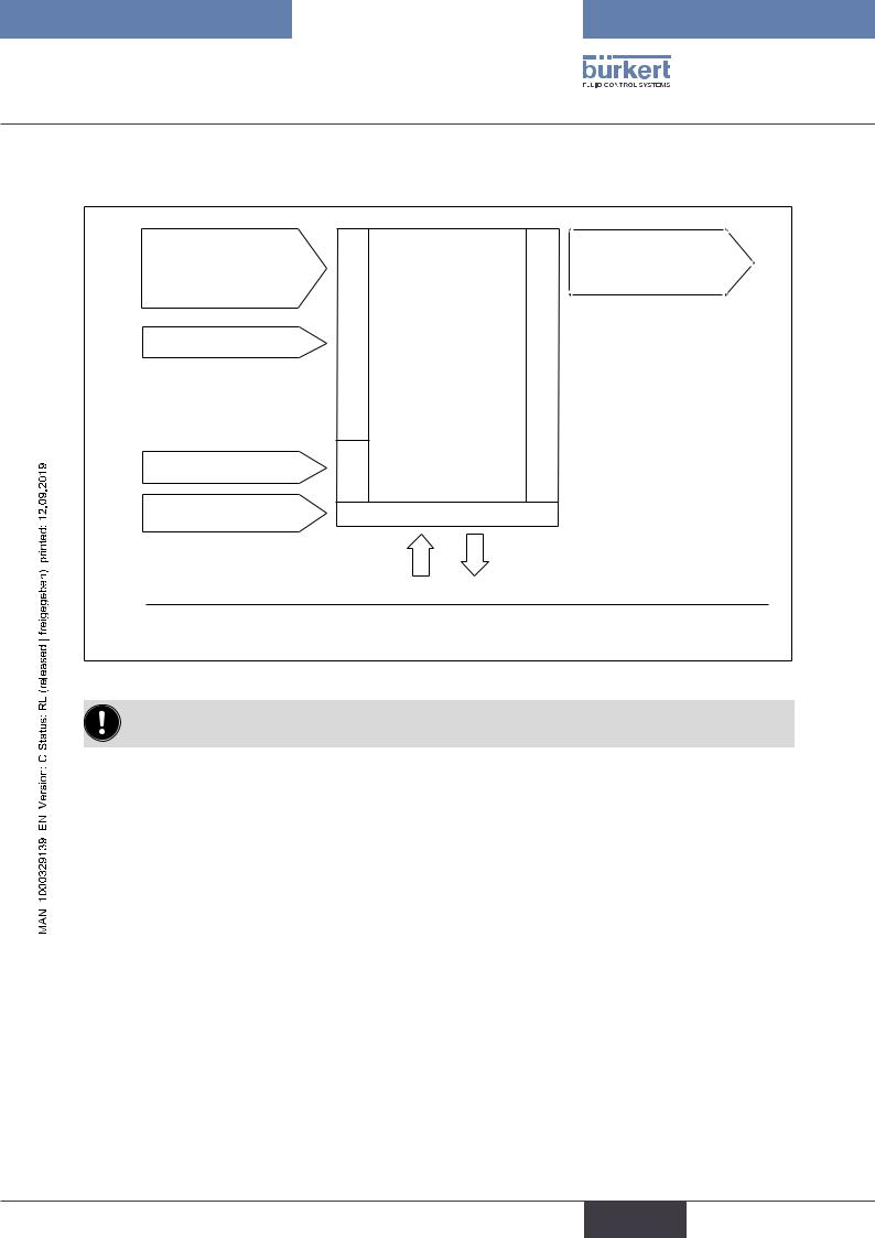
5.6Interfaces of the positioner
|
Input for position |
|
|
Analog |
|
set-point value3) |
|
|
position feedback |
|
4 – 20 mA4) |
|
Positioner |
(optional) |
|
0 – 20 mA |
|
|
|
|
|
|
|
|
|
Binary input |
|
|
|
|
|
Inputs |
|
Outputs |
|
24 V DC |
Power |
|
|
|
Communications |
|
|
|
|
|
Operation |
|
|
|
interface |
|
|
|
|
|
|
|
|
|
3) Or optional bus connection AS interface |
|
|
|
 |
4) Default setting |
|
|
|
Figure 6: |
Interfaces |
|
|
|
The positioner Type 8694 is a 3-wire device, i.e. the power (24 V DC) is supplied separately from the setpoint value signal.
•Input for position set-point value (4 – 20 mA corresponds to 0 – 100 % (depending on position of DIP switch 1)).
•Binary input
If a voltage > 10 V is applied, SAFE POSITION is activated, i.e. the valve is moved to the safety position (factory setting, can be changed with communications software).
•Analog position feedback (optional)
The position of the valve can be transmitted via an analog 4 – 20 mA output to the PLC (4 – 20 mA corresponds to 0 – 100 %).
19
english
Type 8694
Technical data
6TECHNICAL DATA
6.1Conformity
In accordance with the EU Declaration of conformity, the positioner Type 8694 is compliant with the EU Directives.
6.2Standards
The applied standards on the basis of which compliance with the EU Directives is confirmed are listed in the EU type examination certificate and/or the EU Declaration of Conformity.
6.3Licenses
The product is approved for use in zone 2 and 22 in accordance with ATEX directive 2014/34/EU category 3GD.
Observe instructions on operation in an explosion-risk (Ex) area.
Observe the ATEX additional instructions.
The product is cULus approved. Instructions for use in the UL area see chapter “6.8 Electrical data”.
6.4 Operating conditions
 WARNING!
Solar radiation and temperature fluctuations may cause malfunctions or leaks.
If the device is used outdoors, do not expose it unprotected to the weather conditions.
Ensure that the permitted ambient temperature does not exceed the maximum value or drop below the minimum value.
Ambient temperature |
see type label |
||
Degree of protection |
|
|
|
|
|
|
|
Evaluated by the manufacturer: |
|
Evaluated by UL: |
|
|
|
|
|
IP65 / IP67 according to EN 60529 * |
UL Type 4x Rating * |
|
|
|
|
|
|
Operating altitude |
up to 2000 m above sea level |
||
|
|
|
|
* Only if cables, plugs and sockets have been connected correctly and in compliance with the exhaust air concept see chapter “9 Pneumatic installation”.
|
6.5 |
Mechanical data |
|
|
Dimensions |
|
See data sheet |
|
Body material |
exterior: PPS, PC, VA, |
|
|
|
|
interior: PA 6; ABS |
|
Sealing material |
EPDM / (NBR) |
|
20 |
Stroke range of valve spindle: |
2 – 45 mm |
|
|
|
|
|
english
Type 8694
Technical data
6.6Pneumatic data
Control medium |
|
neutral gases, air |
|
|
Quality classes in accordance with ISO 8573-1 |
Dust content |
Quality class 7 |
max. particle size 40 µm, max. particle density 10 mg/m³ |
Water content |
Quality class 3 |
max. pressure dew point |
|
|
- 20 °C or min. 10 °C below the lowest operating temperature |
Oil content |
Quality class X |
max. 25 mg/m³ |
Temperature range |
|
-10 – +50 °C |
of the control medium |
||
Pressure range |
|
3 – 7 bar |
of the control medium |
||
Air output of pilot valve |
7 lN / min (for aeration and deaeration) |
|
|
|
(QNn - value according to definition for pressure drop from 7 to 6 bar |
|
|
absolute) |
|
|
optional: 130 lN / min (for aeration and deaeration) |
|
|
(only single-acting) |
Connections |
|
Plug-in hose connector Ø6 mm / 1/4" |
|
|
Socket connection G1/8 |
6.7Type labels
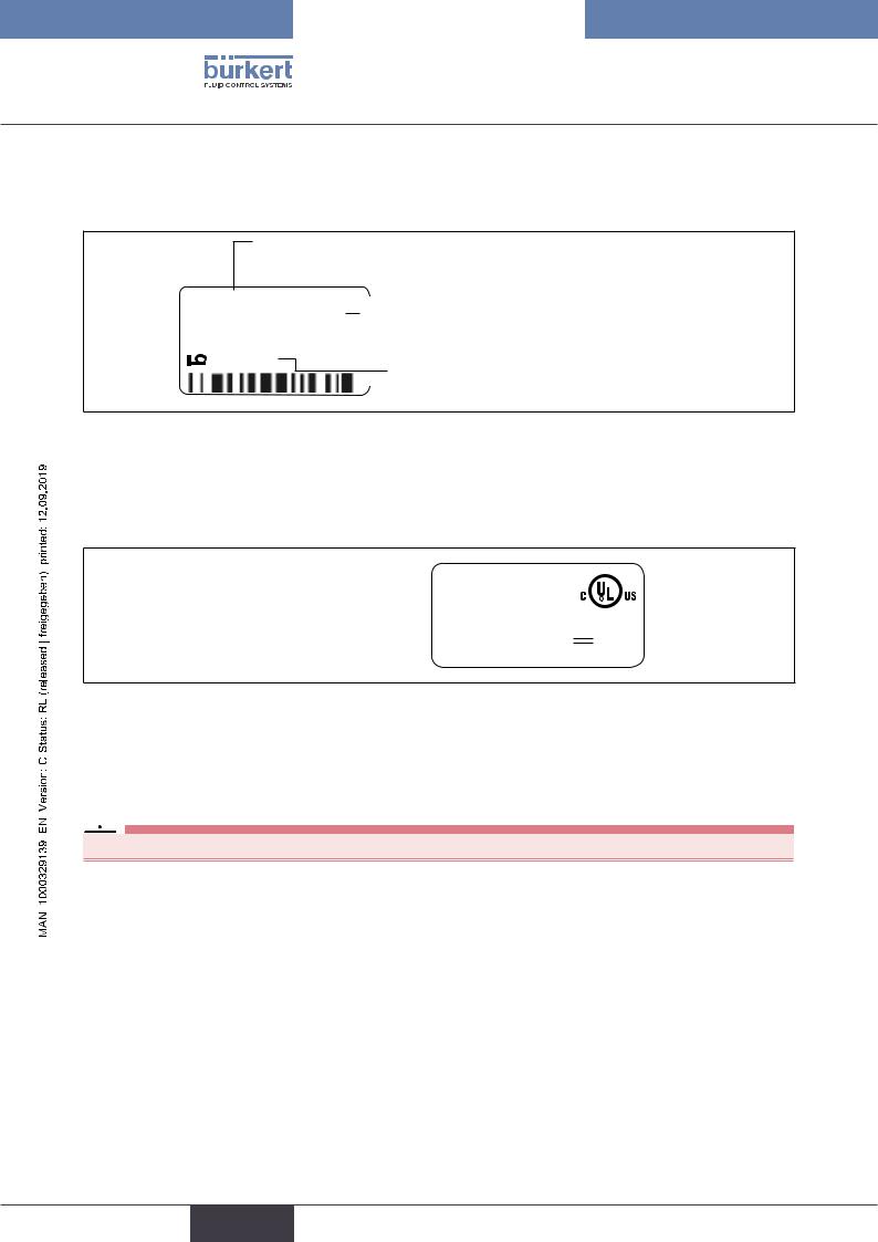
6.7.1Type label standard
Example:
Supply voltage / Control
|
Type |
|
|
|
|
|
8694 24 V DC |
|
|||
|
Ingelfingen |
|
|||
|
|
||||
|
single act Pilot 0,6 |
|
|||
|
|
Pmax 7bar |
|
|
|
|
D-74653 |
Tamb 0°C - +60°C |
CE |
||
|
S/N 001000 |
|
|||
|
00185134 |
W14UN |
|
||
|
|
||||
|
|
|
|||
Identification number
Figure 7: Example of type label
Control function - Pilot valve
Max. operating pressure
Max. ambient temperature  Serial number - CE mark
 Bar-code
21
english
Type 8694
Technical data
6.7.2UL type label
Example:
Type; Features of the type code applicable to UL and ATEX

 D-74653 Ingelfingen
8694 -E3-...-0 Single act Pilot 3.0 Pmax 7 bar
Tamb -10 - +55 °C S/N 1001 00123456
|
|
|
|
|
|
|
|
|
Control function; pilot valve; |
|
|
|
|
|
|
|
|
||
PU02 |
|
|
|
|
|
|
Supply voltage pilot valve |
||
|
|
|
|
|
|
|
|||
24V |
|
|
|
|
|
|
|
|
Max. operating pressure |
|
|
|
|
|
|
|
|
||
|
|
|
|
|
|
|
|
||
|
|
|
|
|
|
|
|
|
|
|
|
|
|
|
|
|
|
||
CE |
|
|
|
|
|
|
Max. ambient temperature |
||
|
|
|
|
|
|||||
|
|
|
|
|
|
Serial number; CE mark |
|||
W15MA |
|
|
|
|
|
|
|||
|
|
|
|
|
|
|
|
|
Identification number; Date of manufacture (encoded) |
|
|
|
|
|
|
|
|
|
Bar code |
|
|
|
|
|
|
|
|||
Figure 8: UL type label (example)
6.7.3 UL additional label
Example:
Degree of protection |
|
Type 4X enclosure |
|
||
Circuit with limited power |
|
NEC Class 2 only |
|
||
Supply voltage device |
|
Supply voltage: 24V |
|
Figure 9: UL additional label (example)
6.8 Electrical data
 WARNING!
Only circuits with limited power may be used for UL approved components according to “NEC Class 2”.
6.8.1Electrical data without bus control 24 V DC
Protection class |
3 as per DIN EN 61140 (VDE 0140-1) |
Connections |
Cable gland M16 x 1.5, wrench size 22 (clamping area 5 – 10 mm) |
|
with screw-type terminals for cable cross-sections 0.14 – 1.5 mm² |
|
Circular plug-in connector (M12 x 1, 8-pole) |
Control valve |
|
Operating voltage |
24 V DC ± 10% - max. residual ripple 10 % |
Power input |
≤ 3.5 W |
Input resistance |
75 Ω at 0/4 - 20 mA / 12 bit resolution |
for set-point value signal |
22
english

Type 8694
Technical data
Analogue position feedback |
|
|
|
max. load |
560 Ω |
||
for current output 0/4 – 20 mA |
|||
Binary input |
0 – 5 V = log “0”, 12 - 30 V = log “1” |
||
|
inverted input in reverse order |
||
Communications interface |
Direct connection to PC via USB adapter with integrated interface driver, |
||
|
communication with communications software, see “Table 34: Accessories”. |
||
|
|
|
|
6.8.2Electrical data with AS-Interface bus control
Protection class |
3 as per DIN EN 61140 (VDE 0140-1) |
Connections |
Circular plug-in connector (M12 x 1, 4-pole) |
Electrical supply voltage |
29.5 V – 31.6 V DC (according to specification) |
Devices without external supply voltage: |
|
Max. power consumption |
150 mA |
Devices with external supply voltage: |
|
External supply voltage |
24 V ± 10 % |
The power supply unit must |
|
include a secure disconnection in |
|
accordance with IEC 364-4-41 |
|
(PELV or SELV) |
|
Max. power consumption |
100 mA |
Max. power consumption |
|
from AS-Interface |
50 mA |
23
english
Type 8694
Technical data
6.9Factory settings of the positioner
Functions can be activated via DIP switches:
Function |
|
Parameter |
Value |
|
|
|
|
CUTOFF |
|
Sealing function below |
2 % |
|
|
Sealing function above |
98 % |
|
|
|
|
CHARACT |
|
Select characteristic |
FREE5) |
|
|
|
|
DIR.CMD |
|
Effective direction set-point value |
rise |
|
|
|
|
Table 4: |
Factory settings - Functions I |
|
|
Functions can be activated via communications software:
Function |
|
Parameter |
Value |
|
|
|
|
INPUT |
|
Set-point value input |
4 ... 20 mA |
|
|
|
|
DIR.ACTUATOR |
Effective direction actual value |
rise |
|
|
|
|
|
SPLITRANGE |
Signal split range below |
0 % |
|
Function deactivated |
Signal split range above |
100 % |
|
|
|
|
|
X.LIMIT |
|
Stroke limit below |
0 % |
Function deactivated |
Stroke limit above |
100 % |
|
|
|
|
|
X.TIME |
|
Actuating time Open |
(1 s) values determined by X.TUNE |
Function deactivated |
Actuating time Closed |
(1 s) values determined by X.TUNE |
|
|
|
|
After implementation of RESET: 1 s |
|
|
|
|
X.CONTROL |
Deadband |
1,0 % |
|
|
|
Open amplification factor |
(1) values determined by X.TUNE |
|
|
Close amplification factor |
(1) values determined by X.TUNE |
|
|
|
After implementation of RESET: 1 |
|
|
|
|
SAFE POSITION |
Safety position |
0 % |
|
|
|
|
|
SIGNAL ERROR |
Sensor break detection set-point value |
OFF |
|
Function deactivated |
|
|
|
|
|
|
|
BINARY INPUT |
Binary input function |
Safety position |
|
|
|
Operating principle of binary input |
Normally open |
|
|
|
|
OUTPUT |
|
Norm signal output: Parameter |
Position |
(optional) |
|
Norm signal output: Type |
4 – 20 mA |
|
|
|
|
Table 5: |
Factory settings Functions II |
|
|
5) Without change to the settings via the communications software a linear characteristic is stored in FREE.
24
english
Type 8694
Control and display elements
7CONTROL AND DISPLAY ELEMENTS
The following chapter describes the operating statuses as well as the control and display elements of the positioner. Further information on the operation of the positioner can be found in the chapter entitled “12 Start-up”.
7.1Operating status
AUTOMATIC (AUTO)
Normal controller mode is implemented and monitored in AUTOMATIC operating status. → LED 1 flashes green.
MANUAL
In MANUAL operating status the valve can be opened and closed manually via the keys. → LED 1 flashes red / green alternately.
DIP switch 4 can be used to switch between the two operating statuses AUTOMATIC and MANUAL.
ON |
|
DIP |
|
1 |
2 |
3 |
4 |
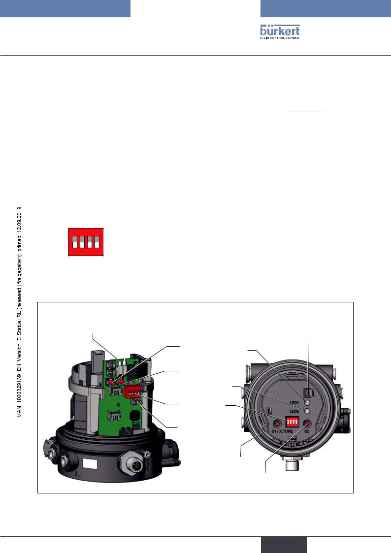
7.2Control and display elements of the positioner
Version 1 |
|
|
|
Version 2 |
LED 1 |
LED 2 |
|
Communications |
|
|
|
|
Key 1 |
interface |
|
|
|
||
|
|
|
LED 1 |
|
|
|
|
|
|
|
|
|
|
|
Key 2
LED 2
|
DIP Switches |
|
Communications |
|
interface |
|
Key 1 |
 |
Key 2 |
|
ON DIP
1 2 3 4
Figure 10: Description of control elements
25
english
Loading...