


Operating Instructions
Bedienungsanleitung
Instructions de Service
Type 1094 Standard
Electronic Controller for Vapor Recovery
Elektronische Steuerung für Gasrückführung
Régulateur èlectronique pour la récupération des vapeurs d’essence
We reserve the right to make technical changes without notice. Technische Änderungen vorbehalten.
Sous resérve de modification techniques.
© 2004 Bürkert Werke GmbH & Co. KG
Operating Instructions 0507/01_EU-ML_00804775

Electronic Control for Vapour Recovery Type 1094 Standard
1 |
GENERAL INFORMATION ........................................................................................................................... |
3 |
|
|
1.1 |
Symbol used ................................................................................................................................. |
3 |
|
1.2 |
Safety instructions ....................................................................................................................... |
3 |
|
1.3 |
Correct usage................................................................................................................................ |
3 |
|
1.4 |
Protection against damage through electrostatic charge .................................................. |
4 |
|
1.5 |
Scope of delivery ......................................................................................................................... |
4 |
|
1.6 |
Guarantee provisions .................................................................................................................. |
4 |
2 |
SYSTEM DESCRIPTION ............................................................................................................................... |
5 |
|
|
2.1 |
General description of the area of use .................................................................................... |
5 |
|
2.2 |
Method of operation of the controller....................................................................................... |
5 |
|
2.3 |
Principle of operation of a petrol pump with vapour recovery............................................ |
6 |
3 |
TECHNICAL DESCRIPTION......................................................................................................................... |
7 |
|
|
3.1 |
General technical data................................................................................................................. |
7 |
|
3.2 |
Electrical data ................................................................................................................................ |
7 |
|
3.3 |
Inputs ............................................................................................................................................... |
7 |
|
3.4 |
Outputs ........................................................................................................................................... |
8 |
4 |
COMMISSIONING AND INSTALLATION ............................................................................................ |
9 |
|
|
4.1 |
Additional important documentation......................................................................................... |
9 |
|
4.2 |
Electrical connections.................................................................................................................. |
9 |
5 |
OPERATION AND FUNCTION .................................................................................................................. |
11 |
|
|
5.1 |
Display elements........................................................................................................................ |
11 |
|
5.2 |
Setting and operation of the controller ................................................................................. |
11 |
|
5.3 |
Calibration of the controller..................................................................................................... |
11 |
|
5.4 |
Puls rate and frequency input ................................................................................................. |
11 |
|
5.5 |
K-factor for the suction rate..................................................................................................... |
12 |
|
5.6 |
Pump after-run time................................................................................................................... |
12 |
|
5.7 |
Petrol pump operation .............................................................................................................. |
12 |
english
1094 - 1
6 MAINTENANCE AND TROUBLE-SHOOTING |
...................................................................................12 |
|
6.1 |
Maintenance................................................................................................................................ |
12 |
6.2 |
Faults ........................................................................................................................................... |
12 |
english
2 - 1094

1 GENERAL INFORMATION
1.1 Symbol used
The following symbols are used in these operation instructions:
marks a working step that you must carry out.
ATTENTION!
Indicates information that must be followed. Failure to do this could endanger your health or the functionality of the device
NOTE |
|
Indicates important additional information, tips and recommen- |
|
|
dations. |
|
|
|
1.2 Safety instructions
To ensure that the device functions correctly and will have a long service life, please comply with the information in these operating instructions as well as the operating conditions and the permissible ranges that are specified in the data sheet.
•When planning the application and the operation of the device, observe the general technical rules!
•The device may not be used in areas endangered by explosion with the characteristics of Zones 0 or 1.
•Take suitable measures to exclude any unintentional operation or impermissible impairment!
•Installation and maintenance work may only be carried out by specialists and with suitable tools!
•Observe the valid regulations for the prevention of accidents and for the safety of electrical devices during the operation and maintenance of the device!
•Always switch of the electrical power before carrying out any work on the system!
•Only use the device in its original configuration!
•If these instructions are ignored or if impermissible interventions are made to the device, no liability will be accepted from our side, and the guarantee on the device and its accessories will also become invalid!
1.3Correct usage
This device is only intended for the electronic control of a proportional valve for vapour recovery on fuel pumps. Any other use, or any use going beyond this will be considered to be improper usage. Bürkert will thereby accept no liability for any resulting damage. The risk will be borne by the user alone.
english
1094 - 3
english
1.4 Protection against damage through electrostatic charge
CAUTION WHEN
HANDLING!
ELECTROSTATICALLY SENSITIVE COMPONENTS / MODULES
The device contains electronic components that are react sensitively to electrostatic discharge (ESD). Contact with electrostatically charged persons or objects will endanger these components. In the worst case, they will be immediately destroyed or will fail after commissioning.
Observe the requirements according to EN 100 015 - 1 in order to minimise or avoid the possibility of damage through sudden electrostatic discharge. You should also ensure that the electronic components do not come into contact with nearby supply voltages.
 1.5 Scope of delivery
Immediately after receipt of the consignment, ensure that the contents have not been damaged, and that they agree with the scope of delivery quoted on the enclosed packaging slip.
In case of a discrepancy, please contact our Customer Service immediately:
Bürkert Steuerund Regelungstechnik
Kundencenter
Chr.-Bürkert-Str. 13-17
D-76453 Ingelfingen
Tel. : 07940-10111
Fax: 07940-10448
E-mail: info@de.buerkert.com
or your local Bürkert distribution centre.
1.6 Guarantee provisions
This document contains no agreement to provide a guarantee. We would refer you here to our General Selling and Business Conditions. The precondition for the guarantee is the correct usage of the device under compliance with the specified application conditions.
ATTENTION!
The guarantee only applies to the freedom of the Type 1094 Standard electronic controller and its components from faults. No liability will be accepted, however, for consequential damage of any kind that could arise from the failure or malfunctioning of the device.
4 - 1094
2 SYSTEM DESCRIPTION
2.1 General description ot the area of use
When refuelling a vehicle, the petrol flowing into the fuel tank displaces an equal volume of petrol vapour out of the tank. In order to prevent this petrol vapour from escaping into the atmosphere, it must be sucked away.
In the solution offered by Bürkert, this suction process takes place by means of underpressure via a proportional valve mounted in front of the reservoir tank of the fuel pump. A suction pump transports the petrol vapour out of the vehicle tank and presses it into the reservoir tank of the petrol pump.
To avoid excessive pressure in the reservoir tank, the volumetric pressure between the petrol being delivered and the returned petrol vapour must be balanced.
The amount of petrol filled into the vehicle tank is measured using a calibrated piston meter in the petrol pump, is converted into pulsed signals by the petrol pump computer and is reported to the controller.
2.2 Method of operation of the controller
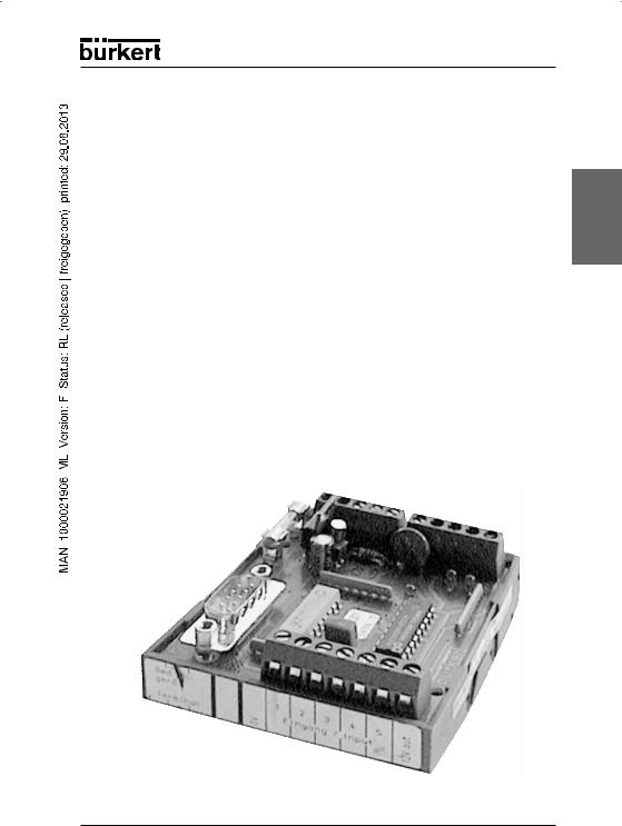
The controller shown on Figure 1 evaluates the pulsed signals from the petrol pump computer and, by means of electrical PWM control signals, controls the area of flow of a control valve (explosion-protected proportional valve of Type 2832) and thereby the flow rate of the returned petrol vapour.
Figure 1: Electronic controller Type 1094 Standard
english
1094 - 5
english
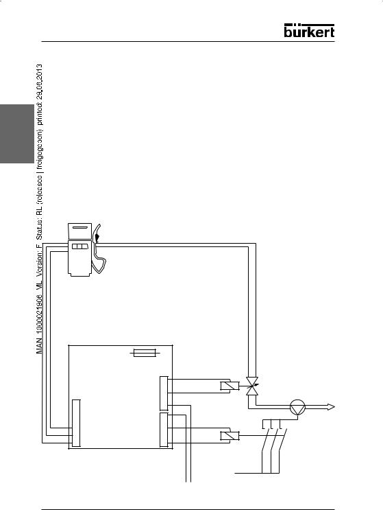
2.3 Principle of operation of a petrol pump with vapour recovery
The valve flow - gas flow characteristic of a pump installation is originally non-linear. In order to ensure an even suction over the complete control range, a linear characteristic is needed. To do this, various points on the characteristic are automatically stored in the controller memory when dimensioning the installation with the control unit. The number of points depends on the characteristic, and will be automatically determined by the control unit. The correction of the characteristic also takes place automatically through linear interpolation between these points.
At the start of the refuelling process, the quantity of petrol tanked will be calculated in the controller from the measured pulse rate. Taking the linearised characteristic and the K-factor of the suction rate into account, the set-value for the valve flow can now be determined, and the proportional valve can be controlled for the suction of the petrol vapour. Together with the control of the proportional valve, the vacuum pump will also be put into operation to generate an underpressure. At the end of the refuelling procedure, the petrol pump computer no longer generates any pulses and the proportional valve for the vapour recovery will be closed. The vacuum pump will also be switched off with an after-run time delay.
Suction line
one or more pulse generator lines from the pulse generator/ petrol pump computer
Control electronics
24 V DC power supply (Type 1610)
Proportional valve
(Type 2332)
Vacuum pump
To the ground tank
24 V DC contactor/ relay for switching the pump motor
Power supply for the vacuum pump
Figure 2: Functional diagram for a petrol pump with vapour recovery
6 - 1094
3 TECHNICAL DESCRIPTION
3.1 General technical data
Ambient temperature |
-25 °C ... +85 °C |
Dimensions |
68 x 76 x 35 mm |
|
Housing |
Open housing for mounting on mounting rails according |
english |
|
|
|
|||
|
|
to DIN EN 50 022 / DIN EN 50 035 / DIN EN 50 045 |
|
|
|
Protection class |
IP 20 |
|
|
|
Order No. |
060 651 |
|
|
3.2 Electrical data |
|
|
|
|
|
|
|
||
|
Supply voltage |
|
|
|
|
|
|
|
|
|
Voltage level |
24 V DC ± 10 % |
|
|
|
Ripple |
< 5 % |
|
|
|
Current comsumption |
< 30 mA (without valve current) |
|
|
|
|
< 300 mA (with valve current) |
|
|
3.3 Inputs |
|
|
|
|
|
Frequency input of the controller |
|
||
|
|
|
|
|
|
High level impulse |
2.5 V ... 25 V |
|
|
|
|
|
|
|
|
Low level impulse |
-1.0 V ... +1.0 V |
|
|
|
|
|
|
|
|
Input impedance |
> 10 kΩ |
|
|
|
|
|
|
|
|
Max. input current |
5 mA |
|
|
|
Min. pulse width |
400 µs |
|
|
|
Rate of measurement |
1 measurement/sec |
|
|
|
Resolution |
1 Hz |
|
|
|
Measurement range |
0 ... 51 l/min |
|
|
|
|
|
|
|
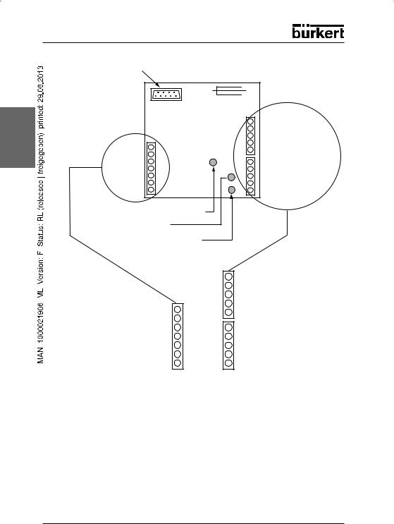
Input 1
Figure 3. Frequency input of the controller
VDD
|
The volumetric flow of the |
|
tanked petrol is measured by |
|
the piston meter, is converted |
|
into a frequency-proportional |
to the |
pulsed signal by the petrol pump |
CPU |
computer and is sent to the |
|
frequency input of the controller |
|
(Figure 3). |
|
In the controller, this pulsed sig- |
|
nal will be processed to obtain |
|
the actual value of the volumetric |
|
flow of the petrol. |
1094 - 7

english
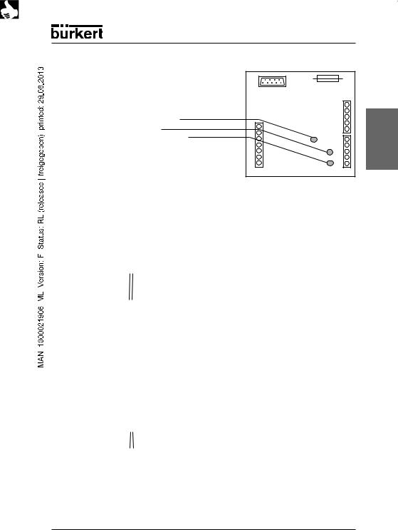
3.4 Outputs
Output for the proportional valve
Output transistor |
Positiv-switching transistor |
|
|
Load current |
0 to 250 mA |
|
|
Output voltage |
24 V DC |
|
|
Clock frequency |
270 Hz |
|
|
Number of outputs |
One valve output each for + and - |
|
|
To regulate the Type 2832 proportional vlave, the controller outputs a current-regu- lated PWM signal via a transistor.
Output for the control of the vaccum pump motor
Output transistor |
„Open-Collector“ transistor output |
|
|
Load current |
100 mA |
|
|
Output voltage |
24 V DC |
|
|
Special freatures |
Freewheeling diode, after-run time adjustable (in con- |
|
nection with the manual control unit Type MKNE-1094) |
|
|
Number of outputs |
One pump output each for + (24 V) and – (GND) |
|
|
The „open-collector“ output shown in Figure 4 is used for the control of a relay/contactor for switching the vacuum pump motor.
The „open-collector“ output is switched active by the controller as long as the proportional valve is open.
|
+ 24 V |
2.2 kΩ |
Output |
from CPU |
|
(Port Bx) |
BC 337 or similar |
|
|
10 kΩ |
|
Figure 4: "Open-Collector" transistor output to the pump controller
8 - 1094
4 COMMISSIONING AND INSTALLATION
4.1 Additional important documentation
ATTENTION!
In order to connect the individual petrol pump components to the Type 1094 controller, you will require the respective interface conditions, such as voltage level, clock rate, impedances, currents, etc. These can be found in the data sheets and/or the operating instructions for the individual components.
NOTE |
You can obtain the complete documentation for the petrol pump |
|
from the supplier or manufacturer of the petrol pump. |
 Have the following documentation at hand for the commissioning of the controller:
•Data sheet/operating instructions for the piston meter/petrol pump computer of the petrol pump
•Data sheet/operating instructions for the proportional valve Type 2832 von Bürkert
•Data sheet/operating instructions for the vacuum pump - required for setting-up the correction factor
•Operating instructions for the Type MKNE-1094 manual control unit from Bürkert
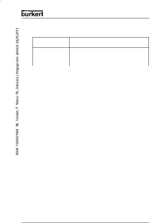
4.2Electrical connections
 Before the commissioning of the controller, carefully connect all the required ports (see Figure 5).
Make the following connections to the controller.
•24 V DC operating voltage
•Output signal for the Type 2832 proportional valve
•Output signal for relay or contactor for the vacuum pump
•Frequency input signal from the petrol pump computer
NOTE Wires/cables
There are no special requirements for the wire connections to be used within the petrol pump, as the currents and/or power to be transmitted are very small.
All cables that are used should be fitted with cable lugs.
The operation and calibration of the controller takes place exclusively via the external Type MKNE-1094e manual control unit, which is connected to the controller using a 9-pole SUB-D plug.
In the case of controllers for the two-sided operation of the petrol pump, a separate SUB-D plug is provided for each side of the petrol pump (Side A and Side B).
english
1094 - 9
english
Connection of the control unit (9-pole SUB-D plug)

 Wire fuse 0.4 A M
Electronic controller
Type 1094 Standard
LED red = active |
Outputs |
|
Inputs
LED "Proportional valve active"
LED "Pump active"
LED "Operating voltage on"
Frequency input (GND) Frequency output 1 (+) not used not used not used not used
Voltage output (+ 12 V) *
Proportional valve (+) Proportional valve (-) Protective contacts PE Protective contacts PE Operational voltage (GND)
Operational voltage (+ 24 V) Output to the pump (+ 24 V) Output to the pump (-)
not used
Voltage input (+ 12 V) *
* The voltage input and voltage output are looped through here.
Figure 5: Electrical connections
10 - 1094
5 OPERATION AND FUNCTION
5.1 Display elements
The controller has 3 red LEDs
For the display of
•„Proportional valve active“
•„Pump motor active“
•„Supply voltage connected“
english |
5.2 Setting and operation of the controller
In order to set up the controller in a petrol pump, all the components, signal lines and the gas gauge from the calibration case must be correctly connected.
The operation and calibration of the controller takes place exclusively using the external Type MKNE-1094 manual control unit, which is connected to the controller using a 9-pole SUB-D plug.
NOTE |
In the case of controllers for the two-sided operation of the petrol |
|
pump, a separate SUB-D plug is provided for each side of the petrol |
|
pump (Side A and Side B). |
The settings that are possible with the manual control unit are described in detail in the Type MKNE-1094 operating instructions.
5.3 Calibration of the controller
The electronic vapour recovery controller is program-controlled and has to be adapted (calibrated) to the real petrol pump process before being used for the first time. The calibration is carried out with the separate (external) MKNE-1094manual control unit. There is a separate set of operating instructions for this external manual control unit. Carefully read through these operating instructions and selection the mode of operation relevant to your application.
NOTE |
Bevore the calibration, the pulse rate, the K-factor and the pump |
|
after-run time must be determined and be entered. |
5.4 Pulsrate and frequency input
The pulse rate output from the petrol pump computer will be defined by the petrol pump manufacturer. The output pulse rate can be set up on the controller with the Type MKNE-1094 manual control unit.
1094 - 11
 Loading...