


Type 8660 |
Control Center |
________________________________________________________
Control Center
Type 8660
(Apparatus Variations 1, 2 and 3)
1.7.1997
- 1 -

Type 8660 |
Control Center |
________________________________________________________
Contents |
Page |
|
1. |
Features and Application Possibilities........................................................... |
4 |
2. |
Notes on Safety............................................................................................. |
5 |
3. |
Installing the Control Center.......................................................................... |
5 |
4. |
Apparatus Variations of the Control Center................................................... |
6 |
5. |
Connections................................................................................................... |
7 |
5.1 |
Wiring diagram.............................................................................................. |
7 |
5.2 |
Signal inputs.................................................................................................. |
10 |
5.3 |
Signal outputs................................................................................................ |
10 |
5.4 |
DIP-switch..................................................................................................... |
12 |
6 |
Structure of Heating and Cooling Systems and Control Center Functions |
13 |
6.1 |
System structure............................................................................................ |
13 |
6.2 |
Functions....................................................................................................... |
14 |
7. |
Operating the Control Center........................................................................ |
16 |
7.1 |
Operating and display elements.................................................................... |
16 |
7.2 |
Operating Options in Operational Mode Ignition off (ZA).............................. |
18 |
7.2.1 |
Overview of operating options in ZA.............................................................. |
18 |
7.2.2 |
Setting the real-time clock in ZA.................................................................... |
18 |
7.2.3 |
Setting the time-switch for the supplementary heater in ZA.......................... |
20 |
7.2.4 |
Changing the air flow direction in ZA............................................................. |
22 |
7.2.5 |
Switching the Defrost function on and off in ZA............................................. |
22 |
7.2.6 |
Changing the temperature set point in ZA..................................................... |
22 |
7.2.7 |
Switching the supplementary heater on and off in ZA................................... |
23 |
7.2.8 |
Switching the fresh air / circulation air flap on and off in ZA.......................... |
23 |
- 2 -

Type 8660 |
Control Center |
||
________________________________________________________ |
|||
Contents |
|
Page |
|
7.3 |
Operating Options in Operational Mode Ignition on and Motor off (ZE)........ |
24 |
|
7.3.1 |
Overview of the possible operating options in ZE......................................... |
|
24 |
7.3.2 |
Changing the air flow direction in ZE............................................................. |
|
24 |
7.3.3 |
Switching the Defrost function on and off in ZE............................................. |
|
24 |
7.3.4 |
Switching level 1 of the front box blower on and off in ZE............................. |
25 |
|
7.3.5 |
Changing the temperature set point in ZE..................................................... |
|
25 |
7.3.6 |
Switching the supplementary heater on and off in ZE................................... |
|
25 |
7.3.7 |
Switching the fresh air / circulation air flap on and off in ZE.......................... |
26 |
|
7.4 |
Operating Options in Operational Mode Motor on (ME)................................ |
26 |
|
7.4.1 |
Overview of the possible operating options in ME......................................... |
|
26 |
7.4.2 |
Changing the air flow direction in ME............................................................ |
|
27 |
7.4.3 |
Switching the Defrost function on and off in ME............................................ |
|
27 |
7.4.4 |
Switching the front box blower on and off in ME........................................... |
|
27 |
7.4.5 |
Changing the temperature set point in ME.................................................... |
|
27 |
7.4.6 |
Switching the supplementary heater on and off in ME.................................. |
28 |
|
7.4.7 |
Switching the driver's seat unit on and off in ME........................................... |
|
28 |
7.4.8 |
Switching the fresh air / circulation air flap on and off in ME......................... |
28 |
|
7.4.9 |
Switching the passenger area floor unit on and off in ME............................. |
29 |
|
7.4.10 |
Switching the passenger area roof unit on and off in ME.............................. |
29 |
|
7.4.11 |
Switching the cooling unit on and off in ME................................................... |
|
30 |
8. |
Valve Check.................................................................................................. |
|
31 |
9. |
Error Message............................................................................................... |
|
31 |
9.1 |
Error message 1 (Err 1)................................................................................. |
|
31 |
9.2 |
Error message 2 (Err 2)................................................................................. |
|
32 |
10. |
Maintenance and Care.................................................................................. |
|
33 |
10.1 |
Maintenance.................................................................................................. |
|
33 |
10.2 |
Care............................................................................................................... |
|
33 |
11. |
Technical Data............................................................................................... |
|
34 |
11.1 |
Electrical Data............................................................................................... |
|
34 |
11.2 |
Mechanical Data............................................................................................ |
|
34 |
- 3 -

Type 8660 |
Control Center |
________________________________________________________
1. Features and Application Possibilities (Overview)
The Control Center is a fully-featured, easy to use, microprocessor-based control unit. Especially designed for the heating and air conditioning of commercial passenger buses, it enables an economical control of the temperature and air flow for the driver and, to a lesser extent, also for the passengers. It has the installation format of an auto radio.
The unit is easy to operate, using keys and three rotatable knobs (rotary switch, rotary potentiometer). Different operational conditions of the heating and cooling system of the passenger bus are shown using a display (digital) and light-emitting diodes (LED).
The Control Center is offered in three variations, which are differentiated by the extensiveness of the controllable capabilities.
Control Center 3 offers the largest range of capability, and is characterized by the following features:
-Outputs for the activation of the front box flaps as well as for the control of a front box valve (driver's area heater), a front box blower, a fresh air / circulation air flap, a cooling unit, a unit in the passenger area roof (for example, blower), a unit in the passenger area floor (for example, heater), a supplementary heater, and a supplementary water pump.
-Real-time clock and programmable time-switch for the supplementary heater.
-Display of the operational condition of the supplementary heater, the cooling unit and the unit in the passenger area roof and floor by means of light-emitting diodes, or on the display.
-System check and error message.
Control Center 2 does not have an output for the control of a cooling unit. Control Center 1 does not offer control of the cooling unit, the supplementary heater and the unit in the passenger area roof, or the real-time clock and the time-switch.
With Control Center 1, the unit in the passenger area floor can only be switched on or off. Control Center 2 and 3 offer two switch levels (for example, two heat levels).
- 4 -

Type 8660 |
Control Center |
________________________________________________________
2. Notes on Safety
To ensure that the Control Center functions faultlessly and has a long life, the user must observe the instructions in this user's manual, and pay attention to the usage conditions and the allowable data according to the data sheet. Installation and maintenance personnel must have been trained and authorized to carry out such activities.
Appropriate measures must be taken to prevent unintended or improper use of the Control Center, and the resulting detrimental influences on the process. After an interruption, a defined and controlled restart of the system, as described in the user's manual, must be carried out.
Secure electrical and fluid isolation devices must be used when the system is being repaired. Control Center repairs may only be carried out by authorized Bürkert technicians.
3. Installing the Control Center
The Control Center has the installation format of an auto radio and can be built into the dashboard without tools, using a mounting frame. It is pushed, together with the mounting frame, into the installation shaft which is provided for this purpose, and locks itself in.
Release levers are used to dismount the system, the same as are used for auto radios. They are entered into the drill holes on the side, until they release the lock. The Control Center is then pulled out of the installation shaft with the release levers.
External dimension of housing ( W x H x D ) |
174 mm |
x 51 mm x 79 mm |
External dimension of front panel ( W x H x D) |
188 mm |
x 58 mm x 8 mm |
Total depth of system with plug strip |
87 mm |
|
- 5 -

Type 8660 |
Control Center |
________________________________________________________
4. Apparatus Variations of the Control Center
The Control Center is offered in three variations, which are differentiated by the extensiveness of the controllable capabilities:
∙Control Center 1
∙Control Center 2
∙Control Center 3
In the following table, the controllable capabilities for each of the three Control Centers are marked with an 'X'.
|
Control Center 1 |
Control Center 2 |
Control Center 3 |
|
|
|
|
front box flaps |
x |
x |
x |
|
|
|
|
front box blower |
x |
x |
x |
|
|
|
|
fresh air / circulation air |
|
x |
x |
flap |
|
|
|
|
|
|
|
driver's seat unit |
x |
|
|
|
|
|
|
passenger area floor unit |
x |
x |
x |
|
|||
|
|
|
|
passenger area roof unit |
|
x |
x |
|
|
||
|
|
|
|
supplementary heater |
|
x |
x |
|
|
|
|
supplementary water |
|
x |
x |
pump |
|
|
|
|
|
|
|
cooling unit |
|
|
x |
|
|
|
|
With Control Center 1, the unit in the passenger area floor can only be switched on or off. Control Center 2 and 3 offer two switch levels.
Control Center 1 does not have a real-time clock or a time-switch for the supplementary heater.
- 6 -
Type 8660 |
Control Center |
________________________________________________________
5. Connections
5.1 Wiring diagram
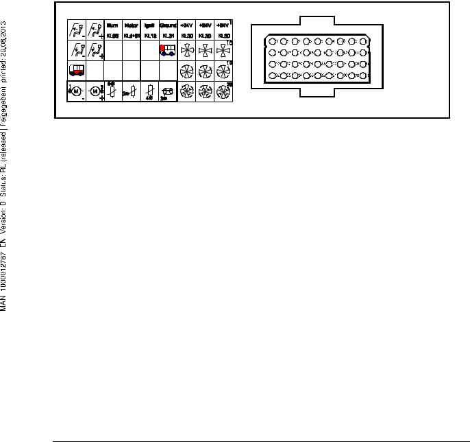
Plug wiring diagram for Control Center 1
Figure 1 shows the backside of Control Center 1 with the plug area (right) and the symbol list for the pins (left). The plug holds pins 1 to 36. The symbols for the individual pins correspond fully with the symbols on the operating elements (see Figure 7 and Figure 8). For further clarification, the plug wiring diagram is described again in words in Figure 2.
Figure 1: Backside of Control Center 1 (Cannon/ITT plug)
Pin |
Connection |
Pin |
Connection |
1 |
24 V |
19 |
front box blower level 2 |
2 |
24 V |
20 |
front box blower level 2 |
3 |
24 V |
21 |
front box blower level 2 |
4 |
ground |
22 |
|
5 |
ignition on (terminal 15) |
23 |
|
6 |
motor on (terminal d+61) |
24 |
|
7 |
illumination (terminal 58) |
25 |
|
8 |
front box flaps windshield |
26 |
|
9 |
front box flaps windshield |
27 |
passenger area floor unit |
10 |
front box blower level 1 |
28 |
front box blower lever 3 |
11 |
front box blower level 1 |
29 |
front box blower lever 3 |
12 |
front box blower level 1 |
30 |
front box blower lever 3 |
13 |
driver's seat unit |
31 |
valve potentiometer, shield |
14 |
|
32 |
valve potentiometer, ground |
15 |
|
33 |
valve potentiometer, sliding contact |
16 |
|
34 |
valve potentiometer, supply + |
17 |
front box flaps floor area |
35 |
front box valve motor |
18 |
front box flaps floor area |
36 |
front box valve motor |
Figure 2: Plug wiring diagram for Control Center 1
- 7 -

Type 8660 |
Control Center |
________________________________________________________
Plug wiring diagram for Control Center 2 and 3
Figure 3 shows the backside of Control Center 2 and 3 with the plug (right) and the symbol list for the pins (left). The plug holds pins 1 to 36. The symbols for the individual pins correspond fully with the symbols on the operating elements (see Figure 7 and Figure 8). For further clarification, the plug wiring diagram is described again in words in Figure 4.
Figure 3: Backside of Control Center 2 and 3 (Cannon/ITT plug)
Pin |
Connection |
Pin |
Connection |
1 |
24 V |
19 |
front box blower level 2 |
2 |
24 V |
20 |
front box blower level 2 |
3 |
24 V |
21 |
front box blower level 2 |
4 |
ground |
22 |
fresh air / circulation air flap + |
5 |
ignition on (terminal 15) |
23 |
fresh air / circulation air flap - |
6 |
motor on (terminal d+61) |
24 |
feedback Cooling unit on (only with CC 3) |
7 |
illumination (terminal 58) |
25 |
cooling unit (only with CC 3) |
8 |
front box flaps windshield |
26 |
passenger area floor unit level 2 |
9 |
front box flaps windshield |
27 |
passenger area floor unit level 1 |
10 |
front box blower level 1 |
28 |
front box blower level 3 |
11 |
front box blower level 1 |
29 |
front box blower level 3 |
12 |
front box blower level 1 |
30 |
front box blower level 3 |
13 |
passenger area roof unit |
31 |
valve potentiometer, shield |
14 |
supplementary water pump |
32 |
valve potentiometer, ground |
15 |
feedback Supplementary heater on |
33 |
valve potentiometer, sliding contact |
16 |
supplementary heater |
34 |
valve potentiometer, supply + |
17 |
front box flaps floor area |
35 |
front box valve motor |
18 |
front box flaps floor area |
36 |
front box valve motor |
- 8 -

Type 8660 |
Control Center |
________________________________________________________
Figure 4: Plug wiring diagram for Control Center 2 and 3 (CC: Control Center)
Reverse polarity protection:
The supply inputs of the Control Center are permanently protected against reverse polarity of ground and plus (up to +30 V DC).
Short circuit protection:
Terminals 35 and 36 (front box valve motor) are only protected against a short circuit with ground, but not against a short circuit with +24 DC.
All of the other inputs and outputs of the Control Center are protected against a short circuit with ground, as well as with plus (up to +30 V DC).
Plug wiring diagram for front box valve:
Pin |
Connection |
Color |
1 |
valve motor |
|
2 |
valve motor |
|
|
|
|
3 |
shield |
|
|
|
|
4 |
potentiometer, GND |
|
|
|
|
5 |
potentiometer, sliding contact |
|
|
|
|
6 |
potentiometer, + |
|
Figure 5: Plug wiring diagram for front box valve (Hirschmann plugs)
- 9 -

Type 8660 |
Control Center |
________________________________________________________
5.2 Signal inputs
- input for feedback Ignition on |
Pin 5 |
- input for feedback Motor on |
Pin 6 |
- input for feedback Illumination on |
Pin 7 |
- input for feedback Supplementary heater on (only for Cont. Cen. 2 + |
3)Pin 15 |
- input for feedback Cooling unit on (only for Control Center 3) |
Pin 24 |
- input for the potentiometer sliding contact connection |
|
of the front box valve |
Pin 33 |
5.3 Signal outputs
Signal outputs for Control Center 1 |
|
- output signal for the control of the front box flaps windshield |
Pin 8, 9 |
(max. 0.5 A) |
|
- output signal for the control of the front box flaps floor area |
Pin 17, 18 |
(max. 0.5 A) |
|
- output signal for the control of the front box blower level 1 |
Pin 10, 11, 12 |
(max. 15 A) |
|
- output signal for the control of the front box blower level 2 |
Pin 19, 20, 21 |
(max. 15 A) |
|
- output signal for the control of the front box blower level 3 |
Pin 28, 29, 30 |
(max. 15 A) |
|
- output signal for the control of a driver's seat unit |
Pin 13 |
(max. 5 A) |
|
- output signal for the control of the passenger area floor unit |
Pin 27 |
(max. 0.5 A) |
|
- output signal for the control of the front box valve |
Pin 35, 36 |
(max. 0.5 A) |
|
- 10 -
Type 8660 |
Control Center |
________________________________________________________
Signal outputs for Control Center 2 and 3 |
|
- output signal for the control of the front box flaps windshield |
Pin 8, 9 |
(max. 0.5 A) |
|
- output signal for the control of the front box flaps floor area |
Pin 17, 18 |
(max. 0.5 A) |
|
- output signal for the control of the front box blower level 1 |
Pin 10, 11, 12 |
(max. 15 A) |
|
- output signal for the control of the front box blower level 2 |
Pin 19, 20, 21 |
(max. 15 A) |
|
- output signal for the control of the front box blower level 3 |
Pin 28, 29, 30 |
(max. 15 A) |
|
- output signal for the control of the passenger area roof unit |
Pin 13 |
(max. 5 A) |
|
- output signal for the control of the supplementary water pump |
Pin 14 |
(max. 0.5 A) |
|
- output signal for the control of the supplementary heater |
Pin 16 |
(max. 0.5 A) |
|
- output signal for the control of the fresh air / circulation air flap |
Pin 22, 23 |
(max. 0.5 A) |
|
- output signal for the control of the cooling units (only Control Center 3) |
Pin 25 |
(max. 0.5 A) |
|
- output signal for the control of the passenger area floor unit, level 1 |
Pin 27 |
(max. 0.5 A) |
|
- output signal for the control of the passenger area floor unit, level 2 |
Pin 26 |
(max. 0.5 A) |
|
- output signal for the control of the front box valve |
Pin 35, 36 |
(max. 0.5 A) |
|
- 11 -

Type 8660 |
Control Center |
________________________________________________________
5.4 DIP-switch
(only for Control Center 2 and 3)
DIP-switch 1: Presettings for the passenger area roof unit
(passenger area blower or roof blower)
Setting on: passenger area blower will be automatically switched on when the motor is switched on, and when the motor is switched off, the blower will also switch off. The blowers can additionally be switched on and off with the appropriate key.
Setting off: passenger area blower will not be automatically switched on.
DIP-switch 2: Presettings for the blower level 1
Setting on: front box blower level 1 will, in Ignition off, be switched on by the time-switch 20 min. after the supplementary heater is switched on, and switched off again after a further 20 min.
Setting off: front box blower level 1 will not be automatically switched on.
The location of the two DIP-switches in the Control Center can be seen in Figure 3.
The DIP-switches must be set before connecting to the power supply.
- 12 -
 Loading...