


Type 1062
Electrical on/off position feedback Elektrischer Auf/Zu-Stellungsrückmelder Indicateur électrique de position tout ou rien
Operating Instructions
Bedienungsanleitung Manuel d‘utilisation

We reserve the right to make technical changes without notice. Technische Änderungen vorbehalten.
Sous réserve de modifications techniques.
© Bürkert SAS, 2008-2013
Operating Instructions 1311/5_EU-ML 00562584 / Original FR

Type 1062
Table of Contents
1. |
About this manual................................................................................. |
5 |
||
|
1.1. |
Symbols used....................................................................................... |
5 |
|
|
1.2. Definition of the word "device".................................................... |
5 |
||
2. |
Intended use............................................................................................... |
6 |
||
|
2.1. |
Restraints................................................................................................ |
6 |
|
|
2.2. |
Ex certification..................................................................................... |
6 |
|
3. |
Basic safety information............................................................... |
7 |
||
4. |
General information........................................................................... |
8 |
||
|
4.1. Manufacturer's address and international contacts......... |
8 |
||
|
4.2. |
Warranty conditions........................................................................... |
8 |
|
|
4.3. Information on the Internet........................................................... |
8 |
||
5. |
Description.................................................................................................. |
9 |
||
|
5.1. |
Area of application............................................................................. |
9 |
|
|
5.2. |
General description........................................................................... |
9 |
|
|
5.2.1. |
Construction........................................................................... |
9 |
|
|
5.2.2. |
Principle of operation............................................................ |
9 |
|
|
5.3. Description of the name plate on the standard 1062..... |
9 |
||
|
5.4. Description of the name plates on the 1062 ATEX....... |
10 |
||
|
5.5. |
Versions available........................................................................... |
11 |
|
6. Technical data........................................................................................ |
11 |
|
6.1. |
Conditions of use............................................................................ |
11 |
6.2. Conformity of the 1062 ATEX to standards |
|
|
|
and directives.................................................................................... |
11 |
6.3. Conformity of the 1062 approved by CSA......................... |
12 |
|
6.4. |
General technical data.................................................................. |
12 |
6.4.1. Mechanical data.................................................................. |
12 |
|
6.4.2. General data........................................................................ |
13 |
|
6.4.3. General data specific to the devices approved by |
|
|
|
CSA....................................................................................... |
14 |
6.4.4. Electrical data...................................................................... |
14 |
|
7. Assembly...................................................................................................... |
16 |
|
7.1. |
Safety instructions.......................................................................... |
16 |
7.2. |
Replacing the top part of an actuator size 40mm......... |
17 |
7.3.Fitting the position feedback to a pneumatic actuator17.
7.4.Fitting the position feedback with stroke
limiter to a pneumatic actuator size 50 to 80mm.......... |
19 |
7.5. Fitting the position feedback with stroke |
|
limiter to a pneumatic actuator size 100 or 125mm.... |
23 |
|
|
|
|
english |
3 |
|
|
|

Type 1062
8. Installation and wiring................................................................. |
26 |
|
8.1. |
Safety instructions.......................................................................... |
26 |
8.2. |
Electrical wiring................................................................................ |
27 |
8.2.1. Wiring a mechanical contact version............................. |
28 |
|
8.2.2. Wiring a version with inductive 2-wire switch............. |
30 |
|
8.2.3. Wiring a version with inductive 3-wire switch............. |
31 |
|
8.2.4.Wiring a version with two inductive 3-wire switches.31
8.2.5.Wiring a version with double inductive 2-wire
|
|
NAMUR switch.................................................................... |
32 |
|
8.2.6. Wiring a version with double inductive 4-wire switch34. |
||
9. Commissioning....................................................................................... |
34 |
||
|
9.1. |
Safety instructions.......................................................................... |
34 |
|
9.2. |
Setting the cams.............................................................................. |
34 |
10. |
Maintenance and troubleshooting............................... |
35 |
|
|
10.1. Safety instructions.......................................................................... |
35 |
|
|
10.2. Cleaning of the transmitter........................................................ |
35 |
|
11. |
Spare parts and accessories.............................................. |
36 |
|
12. |
Packaging, Transport.................................................................. |
36 |
|
13. |
Storage...................................................................................................... |
37 |
|
14. |
Disposal of the product.......................................................... |
37 |
|
|
|
4 |
english |
|
|

Type 1062
About this manual
1About this manual
This manual describes the entire life cycle of the device. Please keep this manual in a safe place, accessible to all users and any new owners.
This manual contains important safety information.
Failure to comply with these instructions can lead to hazardous situations.
This manual must be read and understood.
1.1Symbols used
 danger
Warns you against an imminent danger.
Failure to observe this warning can result in death or in serious injury.
 Warning
Warns you against a potentially dangerous situation.
Failure to observe this warning can result in serious injury or even death.
 Caution
Warns you against a possible risk.
Failure to observe this warning can result in substantial or minor injuries.
NOTE
Warns you against material damage.
Failure to observe this warning may result in damage to the device or system.
indicates additional information, advice or important recommendations for your safety and for the correct operation of the device.
refers to information contained in this manual or in other documents.
→→indicates a procedure to be carried out.
1.2Definition of the word "device"
The word "device" used within this manual refers to the electrical on/ off position feedback type 1062.
|
|
|
|
english |
5 |
|
|
|

Type 1062
Intended use
2Intended use
Use of the 1062 electrical position feedback that does not comply with the instructions could present risks to people, nearby installations and the environment.
The 1062 electrical position feedback, fitted to an on/off valve, is used to detect the status - open or closed - of this valve.
The position feedback can be fitted to an actuator valve with a diameter of 40 to 125 mm.
Protect this device against electromagnetic interference, ultraviolet rays.
Protect a device installed outdoors from the effects of climatic conditions.
Use this device in compliance with the characteristics and commissioning and use conditions specified in the contractual documents and in the user manual.
Requirements for safe and proper operation are proper transport, storage and installation, as well as careful operation and maintenance.
Only use the device as intended.
2.2Ex certification
Ex certification is only valid if modules and components approved by Bürkert are used as indicated in this user manual.
The electronic modules can only be combined with the types of pneumatic valves authorised by Bürkert; if this is not the case, Ex certification is void.
Any modification to the system or to one of the modules or components not authorised beforehand also voids Ex certification.
2.1Restraints
Observe any existing restraints when the device is exported.
|
|
6 |
english |
|
|

Type 1062
Basic safety information
3Basic safety information
This safety information does not take into account:
•any contingencies or occurences that may arise during assembly, use and maintenance of the devices.
•the local safety regulations that the operator must ensure the staff in charge of assembly and/or maintenance observe.
Risk of explosion.
When the 1062 is used in an ATEX 21 or 22 zone, make sure:
•That the cover of the electrical position feedback is always screwed shut before operating the valve.
•That you check that the device is not subject to a flow of air and dust that may result in an accumulation of electrostatic charges. Otherwise, intall the device in a conductive cover.
•"The NAMUR switches on the 1062 must be powered by a voltage source of a type certified for use in explosive atmospheres in groups IIB/IIC and their combination must be compatible from the instrinsic safety point of view."
Danger due to high pressure in the installation.
Shut down the pneumatic power source and depressurise the pipes before carrying out work on the device.
Risk of injury due to electrical discharge.
Shut down the electrical power source of all the conductors and isolate it before carrying out work on the system.
Observe all applicable accident protection and safety regulations for electrical equipment.
Various dangerous situations
To avoid injury take care:
to prevent any power supply switch-on.
to ensure that installation and maintenance work are carried out by qualified and skilled staff with the appropriate tools.
to guarantee a set and controlled restarting of the process, after an electrical and/or pneumatic power supply interruption.
to use the device only if in perfect working order and in compliance with the instructions provided in the user manual.
to observe the general technical rules when locating and using the device.
•not to use non-Ex certified versions of the 1062 electrical position feedback in a potentially explosive atmosphere.
|
|
|
|
english |
7 |
|
|
|

Type 1062
General information
Various dangerous situations (cont'd)
To avoid injury take care:
•not to use outdoors a device approved by CSA.
•not to use this device in an environment incompatible with the materials from which it is made.
•not to subject the device to mechanical loads (e.g. by placing objects on top of it or by using it as a step).
•not to make any external or internal modifications to the device.
NOTE
Elements / Components sensitive to electrostatic discharges
This device contains electronic components sensitive to electrostatic discharges. They may be damaged if they are touched by an electrostatically charged person or object. In the worst case scenario, these components are instantly destroyed or go out of order as soon as they are activated.
To minimise or even avoid all damage due to an electrostatic discharge, take all the precautions described in the EN 61340- 5-1 and 5-2 standards.
Also ensure that you do not touch any of the live electrical components.
4General information
4.1Manufacturer's address and international contacts
To contact the manufacturer of the device, use following address: Bürkert SAS
Rue du Giessen BP 21
F-67220 TRIEMBACH-AU-VAL
You may also contact your local Bürkert sales office.
The addresses of our international sales offices are available on the internet at:
www.burkert.com
4.2Warranty conditions
The condition governing the legal warranty is the conforming use of the 1062 in observance of the operating conditions specified in this manual.
4.3Information on the Internet
You can find the user manuals and the technical data sheets on the 1062 and the INERIS 03ATEX0268 X EC design-examination certificate on the Internet under:
www.burkert.com
|
|
8 |
english |
|
|

Type 1062
Description
5Description
5.1Area of application
The electrical position feedback, combined with a pneumatic valve, is intended to signal the position - open or closed - of this valve.
The position of the valve is given:
•by light(s) and by electrical signal on the mechanical contact versions, on the inductive 3-wire switch (1 output) or double inductive 4-wire switch (2 outputs) or double inductive 2-wire NAMUR switch (2 outputs)
•only by electrical signal on versions with inductive 2-wire switch (1 output).
5.2General description
5.2.1Construction
The electrical position feedback is composed of a housing, fitted with a cable gland, with a transparent cover.
The housing includes:
-- a duplication system that adapts to the pneumatic actuator rod on the valve,
-- one or two electronic boards, each fitted with a mechanical contact limit switch or an inductive switch, with 2 or 3 lights (except for the 2-wire inductive versions)
-- a terminal block for electrical connection.
5.2.2Principle of operation
The duplication rod fitted with 2 cams moves when the valve opens or closes: the movement of a cam past the switch associated with it activates the latter.
When the switch is activated, the light, if there is one, comes on (or goes off on the NAMUR versions) and an electrical signal is transmitted remotely.
This signal is transmitted in accordance with the NAMUR standard on one version of the 1062 ATEX.
5.3Description of the name plate on the standard 1062
1 |
11 |
2 |
|
3
4
5

 Made in France
1062 PROXIMITY SWITCH |
|
|
3-WIRE PNP-NO |
|
10 |
10-30V DC NO/NC |
|
|
MAX:200mA ACTUATOR >80 |
9 |
|
S/N 1199 |
|
|
00560409 W48LP |
|
|
6 |
7 |
8 |
|
||
Fig. 1: Name plate on the 1062 position feedback, standard version
1.Type of device
2.Characteristics of the limit switch
3.Electrical power supply
|
|
|
|
english |
9 |
|
|
|

4.Current consumption
5.Serial number
6.Item number
7.Manufacturing code
8.Conformity Marking
9.Available actuator sizes
10.Mode of operation of the 1062
11.Limit switch type
Type 1062
Description
5.4Description of the name plates on the 1062 ATEX
2
3
4
5
1

 Made in France
6
11
1062 PROXIMITY SWITCH |
|
2-WIRE NAMUR |
10 |
8V DC NO/NC |
|
MAX:15mA ACTUATOR =40 |
9 |
INERIS 03ATEX0268X/02 |
|
0102 |
|
00560411 W48LP |
8 |
|
|
|
7 |
|
12 |
|
|
|
TRIEMBACH |
II 2 GD EEx Ia IIC |
15 |
|
Ex iaD21 T85°C, T100°C |
||
|
|
T6, T5 ou T4 |
|
|
F67220 |
ou T135°C |
|
|
S/N 1000 |
14 |
|
|
|
||
|
|
00560411 W48LP |
|
13 |
6 |
7 |
|
|
|
||
Fig. 2: Name plate on the 1062 position feedback, ATEX version
1.Type of device
2.Characteristics of the limit switch
3.Electrical power supply
4.Current consumption
|
|
10 |
english |
|
|
|
|
|
|
|
|
|
|
|
|
Type 1062 |
|
|
|
|
|
|
|
|
|
|
|
|
|
|
||
|
Technical data |
|
|
|
|
|
|
|
|
|
|
|
|||||
5. |
ATEX certification body and certification number |
6 |
Technical daTA |
|||||
6. |
Item number |
|
|
|
|
|
|
|
7.Manufacturing code
8.Conformity Marking
9.Actuator size
10.Mode of operation
11.Limit switch type
12.Operating zone
13.ATEX logo
14.Serial number
15.Temperature classification
6.1Conditions of use
Ambient temperature |
|
• version approved by CSA and CE |
• 0 to +60 °C |
• version only approved by CE |
• -20 to +60 °C |
Air humidity |
< 80%, non condensated |
|
|
Protection class acc. to EN 60529 |
IP65, when wired and |
|
cable gland tightened |
|
|
5.5Versions available
To find out about the versions of the position feedback available, consult the technical datasheet for the 1062 on our Internet site under:
www.burkert.com
6.2Conformity of the 1062 ATEX to standards and directives
The 1062 ATEX electrical position feedback (version with double inductive 2-wire NAMUR switch) meets the requirements of the ATEX Directive 94/9/EC on equipment intended for use in potentially explosive atmospheres. The following standards have been used in the assessment:
•EN 60079-0 (2004)
•EN 60079-11 (2006)
•EN 61241-0 (2006)
•EN 61241-11 (2007)
|
|
|
|
english |
11 |
|
|
|

Type 1062
Technical data
6.3Conformity of the 1062 approved by CSA
The devices approved by CSA, with variable key PD01, conform to the following standards:
•CSA C22.2 n° 61010-1-04
•UL 61010-1
6.4General technical data
6.4.1Mechanical data
|
PC or PSU |
EPDM |
|
|
PA6 or PPS |
PA or PVDF |
Stainless steel or |
|
brass |
 Brass
Brass
Fig. 3: Materials used in the 1062 position feedback
Component |
Material |
|
|
Housing / Cover |
PA6 / PC or |
|
PPS/PSU |
Component |
|
|
|
Material |
|||||||||||||||||||||
|
|
|
|
|
|
|
|
|
|
|
|
|
|
|
|
|
|
|
|
|
|
|
|
|
|
Seal between the cover and the |
|
|
|
EPDM |
|||||||||||||||||||||
housing |
|
|
|
|
|
|
|
|
|
|
|
|
|
|
|
|
|
|
|
|
|||||
Cable gland M16x1,5 |
|
|
|
PA or PVDF |
|||||||||||||||||||||
|
|
|
|
|
|
|
|
|
|
|
|
|
|
|
|
|
|
|
|
|
|
|
|
|
|
External threaded part |
|
|
|
Brass or stainless steel |
|||||||||||||||||||||
|
|
|
|
|
|
|
|
|
|
|
|
|
|
|
|
|
|
|
|
|
|
|
|
|
|
Internal threaded part |
|
|
|
Brass |
|||||||||||||||||||||
|
|
|
|
|
|
|
|
|
|
|
|
|
|
|
|
|
|
|
|
|
|
|
|
|
|
|
|
|
|
|
|
|
|
|
|
|
|
|
|
|
|
|
|
|
|
|
|
|
|
|
|
67,5 |
|
|
|
|
|
|
|
|
35 |
|
|
|
|
||||||||||||
|
|
|
|
|
|||||||||||||||||||||
|
|
|
|
|
|
Ø 66 |
|
|
|
|
|
|
|
|
|
|
|
|
|
|
|||||
|
|
|
|
|
|
|
|
|
|
|
|
|
|
|
|
|
|
|
|
||||||
|
|
|
|
|
|
|
|
|
|
|
|
|
|
|
|
|
|
|
|
|
|
|
|
|
|
|
|
|
|
|
|
|
|
|
|
|
|
|
|
|
|
|
|
|
|
|
|
|
|
|
|
|
|
|
|
|
|
|
|
|
|
|
|
|
|
|
|
|
|
|
|
|
|
|
|
|
|
87 |
72 |
|
|
M16x1,5 |
- 40 |
|
24 |
|
|
|
|
|
SW27 |
M5 / M6 / M10 |
|
|
|
|
|
12 / 10 / 16 |
M24x1,5 / M26x1,5 / M36x2
Fig. 4: Dimensions of the 1062 position feedback [mm]
|
|
12 |
english |
|
|

Type 1062
Technical data
6.4.2General data
Actuator size |
Ø 40 to 125 mm, depending on the |
||||
|
|
|
version |
||
Mechanical contact |
|
|
|
||
version |
|
|
|
||
• |
type of contact |
• |
in silver or gold |
||
• |
statuses detected |
|
|
|
|
|
-- |
1062 fitted with |
|
-- |
valve open or valve closed |
|
|
one switch |
|
||
|
|
|
|
|
|
|
-- |
1062 fitted with |
|
-- |
valve open and valve closed |
|
|
two switches |
|
||
|
|
|
|
|
|
• valve open or closed |
• using lights and electrical signal via |
||||
|
indication mode |
||||
|
|
terminal block |
|||
|
|
|
|
||
• colour of the lights |
• |
a green light comes on when the valve |
|||
|
depending on the |
||||
|
|
opens ("position open" or "position |
|||
|
status detected |
|
|||
|
|
open and closed" version) and/or a |
|||
|
|
|
|
||
|
|
|
|
red light comes on when the valve |
|
|
|
|
|
closes ("position closed" or "position |
|
|
|
|
|
open and closed" version) |
|
• |
power up light |
• |
orange |
||
|
|
|
|||
Version with inductive |
|
|
|
||
2-wire switch |
|
|
|
||
• statuses detected |
|
|
|
||
-- |
1062 fitted with |
|
-- |
valve open or valve closed |
|
|
one switch |
|
|||
|
|
|
|
||
-- |
1062 fitted with |
|
-- |
valve open and valve closed |
|
|
two switches |
|
|||
|
|
|
|
||
• valve open or closed |
• by electrical signal via terminal block |
||||
indication mode |
|||||
|
|
|
|||
Version with inductive |
|
|
|
||
3-wire switch |
|
|
|
||
• statuses detected |
|
|
|
||
-- |
1062 fitted with |
|
-- |
valve open or valve closed |
|
|
one switch |
|
|||
|
|
|
|
||
-- |
1062 fitted with |
|
-- |
valve open and valve closed |
|
|
two switches |
|
|||
|
|
|
|
||
• valve open or closed |
• using lights and electrical signal via |
||||
indication mode |
|||||
|
terminal block |
||||
|
|
|
|||
• colour of the lights |
• |
a green light comes on when the valve |
|||
depending on the |
|||||
|
opens and a red light comes on when |
||||
status detected |
|
||||
|
the valve closes |
||||
|
|
|
|||
• power up light |
• |
orange |
|||
|
|
||||
|
|
|
|
english |
13 |
|
|
|

Type 1062
Technical data
Version with double |
|
|
inductive switch (4-wire) |
|
|
• |
statuses detected |
• valve open and valve closed |
• valve open or closed |
• using lights and electrical signal via |
|
|
indication mode |
terminal block |
• colour of the lights |
• an orange light comes on when the |
|
|
depending on the |
valve opens and a red light comes on |
|
status detected |
when the valve closes |
• |
power up light |
• green |
Version with double |
|
|
inductive 2-wire NAMUR |
|
|
switch |
|
|
• |
statuses detected |
• valve open and valve closed |
• valve open or closed |
• using lights and electrical signal via |
|
|
indication mode |
terminal block |
• colour of the lights |
• an orange light goes off when the |
|
|
depending on the |
valve opens and a red light goes off |
|
status detected |
when the valve closes |
6.4.3General data specific to the devices approved by CSA
Degree of pollution |
Degree 2, acc. to EN 61010-1 |
|
|
Installation category |
Category I, acc. to EN 61010-1 |
|
|
Height above sea level |
max. 2000 m |
|
|
Electric power |
supplied by an SELV (Safety Extra Low |
|
Voltage) source |
6.4.4Electrical data
Connection cable |
standard, diameter between 5 and |
|||
|
|
7 mm, max cross-section of the strand |
||
|
|
1 mm2 |
||
Mechanical contact |
|
|
|
|
version (per contact) |
|
|
|
|
• |
Power supply of |
• 12-30 V AC or |
||
|
devices approved by |
12-48 V DC |
||
|
CSA and CE |
|
|
|
• |
Power supply |
• 12-30 V DC or |
||
|
of devices only |
12-48 V DC/V AC or |
||
|
approved by CE |
48/110 V DC/V AC or |
||
|
|
110/250 V DC/V AC |
||
• |
Power consumption |
• < 35 mA (48 V DC) |
||
|
|
< 8 mA (220 V AC) |
||
• |
Allowable load |
• depending on the power supply |
||
|
|
voltage and the type of load, inductive |
||
|
|
or resistive: see „Table 1“ next page |
||
|
|
|
|
|
• |
Type of output |
• contact normally open or normally |
||
|
|
closed |
||
|
|
14 |
english |
|
|

Type 1062
Technical data
Version with inductive 2-wire switch (per switch)
• |
Power supply |
• 10-30 V DC |
|
• |
Power consumption |
• |
≤ 2 mA |
• |
Allowable load |
• |
≤ 100 mA |
• |
Type of output |
• contact normally open or normally |
|
|
|
|
closed |
Version with inductive |
|
|
|
3-wire switch (per |
|
|
|
switch) |
|
|
|
• |
Power supply |
• 10-30 V DC |
|
• |
Power consumption |
• |
≤ 25 mA |
• |
Allowable load |
• |
≤ 200 mA |
• |
Type of output |
• NPN or PNP, normally open or nor- |
|
|
|
|
mally closed |
Version with double |
|
|
|
inductive 4-wire switch |
|
|
|
• |
Power supply |
• 10-30 V DC |
|
• |
Power consumption |
• |
≤ 15 mA |
• |
Allowable load |
• ≤ 150 mA, per output |
|
• |
Type of output |
• |
PNP, normally open |
Version with double inductive 2-wire NAMUR switch
• |
Power supply |
• |
8 V DC |
|
|
|
• |
Power consumption |
• ≤ 1,2 mA (activated) and |
||||
|
|
|
> 2,1 mA (not activated) |
|||
• |
Allowable load |
• see table in chap. „8.2.5“ |
||||
• |
Type of output |
• |
acc. to NAMUR |
|
|
|
|
|
|
|
|
|
|
Supply voltage |
|
Inductive load |
|
Resistive load |
||
|
[Imax] |
|
[Imax] |
|||
|
|
|
|
|||
24 V DC |
|
5 A |
|
|
5 A |
|
30 V DC |
|
2 A |
|
|
5 A |
|
50 V DC |
|
0,7 A |
|
|
1 A |
|
74 V DC |
|
0,25 A |
|
|
0,6 A |
|
125 V DC |
|
0,03 A |
|
|
0,4 A |
|
250 V DC |
|
0,02 A |
|
|
0,25 A |
|
125 V AC |
|
8 A |
|
|
8 A |
|
250 V AC |
|
8 A |
|
|
8 A |
|
Table 1: Allowable loads for a mechanical contact version
|
|
|
|
english |
15 |
|
|
|

Type 1062
Assembly
7Assembly
7.1Safety instructions
Risk of explosion.
When the 1062 is used in an ATEX 21 or 22 zone, make sure:
•That the cover of the electrical position feedback is always screwed shut before operating the valve.
 danger
Danger due to high pressure in the installation.
Shut down the pneumatic power source and depressurise the pipes before carrying out work on the device.
Risk of injury due to electrical discharge.
Shut down the electrical power source of all the conductors and isolate it before carrying out work on the system.
Observe all applicable accident protection and safety regulations for electrical equipment.
 Warning
Risk of injury due to non-conforming assembly.
The device must only be assembled by qualified and skilled staff with the appropriate tools.
Risk of injury due to unintentional switch on of power supply or uncontrolled restarting of the installation.
Avoid unintentional activation of the installation.
Guarantee a set or controlled restarting of the process subsequent to the assembly of the device.
|
|
16 |
english |
|
|

Type 1062
Assembly
7.2Replacing the top part of an actuator size 40mm
NOTE
The tightness of the actuator is not guaranteed when the cover is removed.
Prevent the projection of fluids into the actuator.
|
|
|
B |
|
→→Remove the top part |
|
of the actuator, "A", |
|
|
|
|
|
A |
by unscrewing it with |
|
the spanner available |
|
|
|
|
|
|
in accessories (item |
|
|
number 639175). |
→→Remove the top part of the actuator rod, "B", by unscrewing by
hand.
→→Screw the top part of the actuator supplied with the 1062 to the actuator size 40mm, and tighten it using the spanner (item number 639175).
Fig. 5: Replacing the top part of the actuator size 40mm
7.3Fitting the position feedback to a pneumatic actuator
NOTE
The tightness of the actuator is not guaranteed when the transparent cap is removed.
Prevent the projection of fluids into the actuator.
The tightness of the position feedback is not guaranteed when the cover is removed.
Prevent the projection of fluids into the position feedback.
The position feedback may be damaged if a metal component comes into contact with the electronics.
Prevent contact of the electronics with a metal component (a screwdriver, for example).
|
→→If the valve is fitted with an actuator |
|
size 40mm, replace the top part of the |
|
actuator. See chap. „7.2“. |
|
→→Unscrew the cone point set screw "C" |
|
from the 1062 to unlock the dupli- |
C |
cation system "D" using a hexagonal |
male spanner. |
|
D |
→→Carefully remove the duplication |
|
system "D" from the housing of the |
|
1062. |
|
|
|
|
english |
17 |
|
|
|

Type 1062
Assembly
|
|
|
|
|
|
|
|
|
|
|
|
|
|
|
|
|
|
|
→→Check that the seals have been fitted |
|
|
|
|
|
|
|
|
|
|
|
|
|
|
|
|
|
|
|
|
|
|
|
|
|
|
|
|
|
and that they are undamaged. Replace |
|
|
|
|
|
|
|
|
|
|
|
|
|
|
|
|
|
|
|
them if necessary. |
|
|
|
|
|
|
|
|
|
→→Put thread lock into the internal thread |
|
|
|
|
|
|
|
|
|
|
|
|
|
|
|
|
E |
in the duplication rod "E". |
||
|
|
|
|
|
|
||||
|
|
|
|
|
|
||||
|
|
|
|
|
|
||||
|
|
|
|
|
|
|
|||
|
|
|
|
|
|
|
|||
|
|
|
|
|
|
|
|||
|
|
|
|
|
|
|
|||
|
|
|
|
|
|
|
|
|
|
|
|
|
|
|
|
|
|
F |
→→Unscrew the small transparent cap "F" |
|
|
|
|
|
|
|
|
on the actuator, preferably by hand or |
|
|
|
|
|
|
|
|
|
|
|
|
|
|
|
|
|
|
G |
using a suitable tool in order not to |
|
|
|
|
|
|
|
|
damage it (except for actuators size |
||
|
|
|
|
|
|
|
|||
|
|
|
|
|
|
|
|
|
40mm). |
|
|
|
|
|
|
|
|
|
→→Pump air into the actuator on a valve |
|
|
|
|
|
|
|
|
|
which is normally closed (function "A") |
|
|
|
|
|
|
|
|
|
or has a double effect (function "I") so |
|
|
|
|
|
|
|
|
|
that the actuator rod moves to the top |
|
|
|
|
|
|
|
|
|
position. |
|
|
|
|
|
|
|
|
|
→→Unscrew the visual position feedback |
|
|
|
|
|
|
|
|
|
"G" using a hexagonal male spanner. |
→→Check that the seal "H" is fitted and that it is correctly positioned inside the actuator.
→→Insert the duplication system "D" into the actuator.
→→Screw the duplication rod "E" onto the actuator rod "J".
→→Tighten the adaptor until free contact is obtained with the top of the actuator, using a flat No 27 spanner.
|
|
18 |
english |
|
|

Type 1062
Assembly
→→Fully tighten the duplication rod on the actuator rod using a screwdriver with a blade of suitable size.
→→Depressurize the actuator of a valve which is normally closed (function "A") or has a double effect (function "I"): the valve recovers its default position.
|
→→Insert the position feedback housing |
|
into the duplication system "D" |
|
setting the cable gland in the |
|
direction desired and making sure, |
|
on a mechanical contact version, |
|
that you do not damage the contact |
DC |
levers on the switches. |
→→Fasten the housing and the dupli- |
|
|
cation system by tightening the cone |
|
point set screw "C" using a hex- |
|
agonal male spanner. |
|
→→Unscrew the cover "K" on the |
|
position feedback. |
|
→→Unscrew the cable gland "L". |
K |
→→Thread the cable through the cable |
|
gland. |
|
→→Wire according to the wiring |
|
diagram for your version of the 1062: |
|
See chap. „8 Installation and wiring“. |
|
→→Fasten the cable gland to ensure |
|
tightness of the product. |
L |
|
7.4Fitting the position feedback with stroke limiter to a pneumatic actuator size 50 to 80mm
NOTE
The tightness of the actuator is not guaranteed when the transparent cap is removed.
Prevent the projection of fluids into the actuator.
The tightness of the position feedback is not guaranteed when the cover is removed.
Prevent the projection of fluids into the position feedback.
|
|
|
|
english |
19 |
|
|
|

Type 1062
Assembly
NOTE
The position feedback may be damaged if a metal component comes into contact with the electronics.
Prevent contact of the electronics with a metal component (a screwdriver, for example).
→→Unscrew the cone point set screw "C" from the 1062 to unlock the duplication system "D" using a hexagonal male spanner.
|
→→Carefully remove the duplication |
C |
system "D" from the housing of |
the 1062. |
|
D |
|
→→Check that the seals have been fitted and that they are undamaged. Replace them if necessary.
→→Put thread lock into the internal thread in the duplication rod "E".
 E
E
|
|
|
|
|
|
|
|
|
|
F |
→→Unscrew the small transparent |
|
|
|
|
cap "F" on the actuator, pre- |
|
|
|
|
|
|
|
|
|
|
G |
ferably by hand or using a sui- |
|
|
|
|
table tool in order not to damage |
||
|
|
|
|||
|
|
|
|
|
it (except for actuators size |
|
|
|
|
|
40mm). |
|
|
|
|
|
→→Pump air into the actuator on a |
|
|
|
|
|
valve which is normally closed |
|
|
|
|
|
(function "A") or has a double |
|
|
|
|
|
effect (function "I") so that the |
|
|
|
|
|
actuator rod moves to the top |
|
|
|
|
|
position. |
|
|
|
|
|
→→Unscrew the visual position |
|
|
|
|
|
feedback "G" using a hexagonal |
|
|
|
|
|
male spanner. |
|
|
20 |
english |
|
|
Type 1062
Assembly
→→Check that the seal "H" is fitted and that it is correctly positioned inside the actuator.
→→Screw the adapter nut "J" in the top part of the actuator.
→→Screw the connecting pin "K" with locknut "L" in the adapter nut "J".
→→Adjust the stroke of the actuator (by more or less screwing the connecting pin "K") depending on the operating mode of the valve:
-- if the valve operates as normally closed (NC), adjust the stroke by starting valve closed.
-- if the valve operates as normally open (NO), adjust the stroke by starting valve open.
→→Block the locknut "L".
→→Insert the seal "M" in the connecting pin "K".
→→Screw the stem "N" on the stem "O" of the actuator.
→→Insert the protection hood "P".
P
→→Insert the duplication system "D" into the stroke limiter.
D
|
|
|
|
english |
21 |
|
|
|

Type 1062
Assembly
→→Tighten the duplication system "D" until free contact is obtained with the top of
D the limiter, using a flat No 27 spanner.
→→Fully tighten the duplication rod on the actuator rod using a screwdriver with a blade of suitable size.
→→Depressurize the actuator of a valve which is normally closed (function "A") or has a double effect (function "I"): the valve recovers its default position.
|
→→Insert the position feedback |
|
|
housing into the duplication |
|
|
system "D" setting the |
|
|
cable gland in the direction |
|
|
desired and making sure, on |
|
|
a mechanical contact version, |
|
C |
that you do not damage the |
|
D |
contact levers on the switches. |
|
→→Fasten the housing and the |
||
|
||
|
duplication system by tight- |
|
|
ening the cone point set screw |
|
|
"C" using a hexagonal male |
|
|
spanner. |
|
|
→→Unscrew the cover "Q" on the |
|
|
position feedback. |
|
|
→→Unscrew the cable gland "R". |
|
Q |
→→Thread the cable through the |
|
|
cable gland. |
|
|
→→Wire according to the wiring |
|
|
diagram for your version of the |
|
|
1062: See chap. „8 Installation |
|
|
and wiring“. |
|
|
→→Fasten the cable gland to |
|
|
ensure tightness of the product. |
|
R |
|
|
|
22 |
english |
|
|

Type 1062
Assembly
7.5Fitting the position feedback with stroke limiter to a pneumatic actuator size 100 or 125mm
NOTE
The tightness of the actuator is not guaranteed when the transparent cap is removed.
Prevent the projection of fluids into the actuator.
The tightness of the position feedback is not guaranteed when the cover is removed.
Prevent the projection of fluids into the position feedback.
The position feedback may be damaged if a metal component comes into contact with the electronics.
Prevent contact of the electronics with a metal component (a screwdriver, for example).
→→Unscrew the cone point set screw "C" from the 1062 to unlock the duplication system "D" using a hexagonal male spanner.
|
→→Carefully remove the duplication |
C |
system "D" from the housing of |
the 1062. |
|
D |
|
|
|
|
|
|
|
|
|
|
|
|
|
|
|
|
→→Check that the seals have |
|
|
|
|
|
|
|
|
|
|
|
|
|
|
|
|
|
|
|
|
|
|
|
been fitted and that they are |
|
|
|
|
|
|
|
|
|
|
|
|
|
|
|
undamaged. Replace them if |
|
|
|
|
|
|
|
necessary. |
|
|
|
|
|
|
|
→→Put thread lock into the internal |
|
|
|
|
|
|
|
|
|
|
|
|
|
|
|
|
|
|
|
|
|
|
|
|
|
|
|
|
|
|
E |
thread in the duplication rod "E". |
|
|
|
|
|
|
||
|
|
|
|
|
|
|
|
|
|
|
|
|
|
|
|
|
|
|
|
|
|
|
|
|
|
|
|
|
|
F |
→→Unscrew the small transparent |
|
|
|
|
|
|
cap "F" on the actuator, pre- |
|
|
|
|
|
|
|
|
|
|
|
|
G |
ferably by hand or using a sui- |
|||
|
|
|
table tool in order not to damage |
||||
|
|
|
|||||
|
|
|
|
|
|
|
it |
|
|
|
|
|
|
|
→→Pump air into the actuator on a |
|
|
|
|
|
|
|
valve which is normally closed |
|
|
|
|
|
|
|
(function "A") or has a double |
|
|
|
|
|
|
|
effect (function "I") so that the |
|
|
|
|
|
|
|
actuator rod moves to the top |
|
|
|
|
|
|
|
position. |
|
|
|
|
|
|
|
→→Unscrew the visual position |
|
|
|
|
|
|
|
feedback "G" using a hexagonal |
|
|
|
|
|
|
|
male spanner. |
|
|
|
|
english |
23 |
|
|
|

Type 1062
Assembly
→→Remove the top part "H" of the H actuator, by unscrewing it with the spanner available in accessories (item number 639172 for an actuator size 100mm or item number 639173 for an actuator
size 125mm).
M |
K |
→→Insert the seal "J" into the groove |
|
of the adaptater nut "K". |
|||
|
|||
|
|
||
|
J |
→→Screw the adaptater nut "K" in |
|
|
|
the top part of the actuator. |
|
|
|
→→Screw the locknut "L" on "K", |
|
|
|
inside the top hat of the actuator. |
|
|
|
→→Insert the seal "M" into the adap- |
|
|
|
tater nut "K". |
|
|
L |
→→Screw back the top part of the |
|
|
actuator. |
||
|
|
Q |
→→Screw the connecting pin "N" |
|
with the locknut "O" in the |
||
|
||
P |
adapter nut "K". |
|
→→Adjust the stroke of the actuator |
||
N |
(by more or less screwing the |
|
O |
connecting pin "N") depending |
|
on the operating mode of the |
||
|
valve: |
|
|
-- if the valve operates as nor- |
|
|
mally closed (NC), adjust |
|
|
the stroke by starting valve |
|
|
closed. |
|
|
-- if the valve operates as nor- |
|
|
mally open (NO), adjust the |
|
|
stroke by starting valve open. |
|
|
→→Block the locknut "O". |
|
|
→→Insert the seal "P" in the con- |
|
|
necting pin "N". |
|
|
→→Screw the stem "Q" on the |
|
|
stem "R" of the actuator. |
|
R |
|
|
|
24 |
english |
|
|

Type 1062
Assembly
→→Insert the duplication system "D" into the stroke limiter.
D
→→Tighten the duplication system "D" until free contact is obtained with the top of
D the limiter, using a flat No 27 spanner.
D
→→Fully tighten the duplication rod on the actuator rod using a screwdriver with a blade of suitable size.
→→Depressurize the actuator of a valve which is normally closed (function "A") or has a double effect (function "I"): the valve recovers its default position.
|
|
|
|
english |
25 |
|
|
|

Type 1062
Installation and wiring
|
→→Insert the position feedback |
|
|
housing into the duplication |
|
|
system "D" setting the |
|
|
cable gland in the direction |
|
|
desired and making sure, on |
|
|
a mechanical contact version, |
|
C |
that you do not damage the |
|
D |
contact levers on the switches. |
|
→→Fasten the housing and the |
||
|
||
|
duplication system by tight- |
|
|
ening the cone point set screw |
|
|
"C" using a hexagonal male |
|
|
spanner. |
|
|
→→Unscrew the cover "R" on the |
|
|
position feedback. |
|
|
→→Unscrew the cable gland "S". |
|
R |
→→Thread the cable through the |
|
cable gland. |
||
|
||
|
→→Wire according to the wiring |
|
|
diagram for your version of the |
|
|
1062: See chap. „8 Installation |
|
|
and wiring“. |
|
|
→→Fasten the cable gland to |
|
|
ensure tightness of the product. |
|
S |
|
8Installation and wiring
8.1Safety instructions
Risk of explosion.
When the 1062 is used in an ATEX 21 or 22 zone, make sure:
•That the cover of the electrical position feedback is always screwed shut before operating the valve.
•That you check that the device is not subject to a flow of air and dust that may result in an accumulation of electrostatic charges. Otherwise, intall the device in a conductive cover.
•"The NAMUR switches on the 1062 must be powered by a voltage source of a type certified for use in explosive atmospheres in groups IIB/IIC and their combination must be compatible from the instrinsic safety point of view."
|
|
26 |
english |
|
|

Type 1062
Installation and wiring
 danger
Danger due to high pressure in the installation.
Shut down the pneumatic power source and depressurise the pipes before carrying out work on the device.
Risk of injury due to electrical discharge.
Shut down the electrical power source of all the conductors and isolate it before carrying out work on the system.
Observe all applicable accident protection and safety regulations for electrical equipment.
 Warning
Risk of injury due to nonconforming installation.
Electrical installation can only be carried out by qualified and skilled staff with the appropriate tools.
Install appropriate safety devices (correctly rated fuse and/or circuit-breaker).
Risk of injury due to unintentional switch on of power supply or uncontrolled restarting of the installation.
Take appropriate measures to avoid unintentional activation of the installation.
Guarantee a set or controlled restarting of the process subsequent to the assembly of the device.
8.2Electrical wiring
 danger
Risk of injury due to electrical discharge.
Shut down the electrical power source of all the conductors and isolate it before carrying out work on the system.
Observe all applicable accident protection and safety regulations for electrical equipment.
Use a high quality electrical power supply (filtered and regulated).
NOTE
The tightness of the position feedback is not guaranteed when the cover is removed.
Prevent the projection of fluids into the position feedback.
The position feedback may be damaged if a metal component comes into contact with the electronics.
Prevent contact of the electronics with a metal component (a screwdriver, for example).
→→Assemble the device as shown in chap. „7 Assembly“ before wiring it.
→→Carry out the electrical wiring in accordance with chap. „8.2.1“ to „8.2.6“ for your version of the 1062.
→→Once the device has been wired, lock the cable so that it does not impair the mobility of the duplication rod, by inserting it
|
|
|
|
english |
27 |
|
|
|
Type 1062
Installation and wiring
into the notches provided for this purpose in the bottom of the housing, as shown in „Fig. 6“ below:
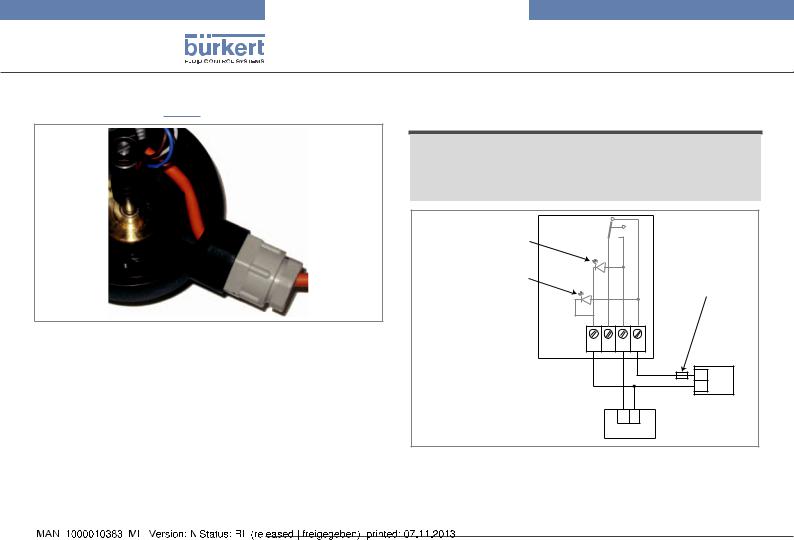
8.2.1Wiring a mechanical contact version
NOTE
On a mechanical contact version, the used contact is not voltage free.
•Do not connect the unused contact in order to obviate any danger of malfunction.
|
Green light (open |
|
|
|
|
|
valve detection) |
|
|
|
Orange light (volt- |
|
Fuse suitable for |
|
|
|
age present) |
|
the max. load |
Fig. 6: |
Final position of the cable |
|
- NCNO + |
|
|
|
1062 |
||
|
|
|
|
+ |
|
|
|
|
- |
|
|
Load |
Power supply 1) |
|
|
|
+ - |
||
|
|
|
|
8 A max. |
|
Fig. 7: |
Wiring of the contact when normally open (NO) on a |
||
|
|
mechanical contact version, valve open detection |
||
|
1) Use a power supply that matches the data shown on the name plate of the |
|||
|
1062 |
|
|
|
|
|
28 |
english |
|
|

Type 1062
Installation and wiring
Green light (open |
|
|
valve detection) |
|
|
Orange light (volt- |
Fuse suitable for |
|
the max. load |
||
age present) |
||
|
||
1062 |
- NCNO + |
|
|
+ |
|
|
- |
|
|
Power supply 1) |
+ -
8 A max.
Load
Fig. 8: Wiring of the contact when normally closed (NC) on a mechanical contact version, valve open detection
1) Use a power supply that matches the data shown on the name plate of the 1062
Red light (valve closed detection)
Orange light (voltage present)
|
Fuse suitable for |
|
the max. load |
1062 |
- NCNO + |
|
|
|
+ |
|
- |
|
Power supply 1) |
|
+ - |
|
8 A max. |
Load
Fig. 9: Wiring of the contact when normally open (NO) on a mechanical contact version, valve closed detection
1) Use a power supply that matches the data shown on the name plate of the 1062
|
|
|
|
english |
29 |
|
|
|

|
|
|
|
Type 1062 |
|
|
|
|
|
Installation and wiring |
|
|
|
|
8.2.2 Wiring a version with inductive |
||
Red light (valve closed |
|
|
2-wire switch |
|
|
|
|
|
|
|
|
detection) |
|
|
|
Reaction speed according |
|
|
|
|
|
||
Orange light (volt- |
|
Fuse suitable for |
|
to the max. load |
|
age present) |
|
the max. load |
|
|
|
|
|
|
1062 + - |
|
|
|
1062 |
- NCNO + |
|
125 mA |
+ |
|
|
|
|
- 10-30 VDC |
|
|
|
+ |
Load |
+ - |
Power supply |
|
|
- |
|
100 mA max. |
|
|
|
Power supply 1) |
Fig. 11: Wiring the inductive 2-wire switch in "less common" |
||
|
|
+ - |
|||
|
|
mode, open and/or closed valve detection |
|||
8 A max.
|
Load |
|
|
|
|
|
|
|
|
|
|
|
|
|
|
Reaction speed according |
|||||||
|
|
|
|
|
|
|
|
|
|
|
|
|
|
|
|||||||||
|
|
|
|
|
|
|
|
|
|
|
|
|
|
|
|||||||||
|
|
|
|
|
|
|
|
|
|
|
|
|
|
|
|
to the max. load |
|||||||
|
|
|
|
|
|
|
|
|
|
|
|
|
|
|
|
||||||||
Fig. 10: Wiring of the contact when normally closed (NC) on a |
|
|
|
|
|
|
|
|
|
|
|
|
|
|
|
|
|
|
|
|
|
|
|
|
|
|
|
|
|
|
|
|
|
|
|
|
|
|
|
|
|
|
|
|
|
||
|
mechanical contact version, valve closed detection |
|
|
1062 |
|
+ |
- |
|
|
|
|
|
|
|
|
|
|
|
|||||
1) |
Use a power supply that matches the data shown on the name plate of the |
|
|
|
|
|
|
|
|
|
|
|
|
|
|||||||||
|
|
|
|
|
|
|
|
|
|
|
|
|
|
125 mA |
|
|
|
||||||
1062 |
|
|
|
|
|
|
|
|
|
|
|
|
|
|
|
|
|||||||
|
|
|
|
|
|
|
|
|
|
|
|
|
+ |
10-30 VDC |
|
||||||||
|
|
|
Load |
|
|
|
|
|
|
|
|
|
|
|
|
|
|
|
|
- |
|
||
|
|
|
|
|
|
|
|
|
|
|
|
|
|
|
|
|
|
|
|
|
|
||
|
|
|
|
|
|
|
|
|
|
|
|
|
|
|
|
|
Power supply |
||||||
|
|
|
|
|
+ |
- |
|
|
|
|
|
|
|
|
|||||||||
|
|
|
|
|
100 mA max. |
|
|
|
|
|
|
|
|
|
|||||||||
|
|
|
|
|
|
|
|
|
|
|
|
|
|
|
|
|
|
|
|
|
|
|
|
|
|
|
Fig. 12: Wiring the inductive 2-wire switch in "more common" |
||||||||||||||||||||
|
|
|
mode, open and/or closed valve detection |
||||||||||||||||||||
|
|
30 |
english |
|
|
 Loading...