


We reserve the right to make technical changes without notice.
Technische Änderungen vorbehalten.
Sous réserve de modifications techniques.
www.burkert.com
© 2008 – 2012 Bürkert Werke GmbH
Operating Instructions 1201/05_EU-ml_00805637/ Original DE
1.QUICKSTART
The operating instructions describe the entire life cycle of the device. Keep these instructions in a location which is easily accessible to every user and make these instructions available to every new owner of the device.
Important Safety Information!
Read Quickstart carefully and thoroughly. Study in par ticular the chapters entitled “4. Basic Safety Instructions” and “3. Intended Use”.
• Quickstart must be read and understood.
Quickstart for Type 8605 explains, for example, how to install and start-up the device.
A detailed description of the device can be found in the operating instructions for Type 8605. These instructions also include the warranty provisions and details about the correct disposal of the device.
The operating instructions can be found on the enclosed CD and on the Internet at:
www.burkert.com Documentation
 Type 8605
1.1. Definition of Term “Device”
The term “device” used in these instructions always stands for the electromagnetic positioner type 8791.
Type 8605
Digital Control Electronics for Proportional Valves Digitale Ansteuerelektronik für Proportionalventile
Régulateur électronique numérique pour vannes proportionnelles
Quickstart
English
Deutsch
Français
2.SYMBOLS
The following symbols are used in these instructions.
 DANGER!
Warns of an immediate danger!
•Failure to observe the warning may result in a fatal or serious injury.
 WARNING!
Warns of a potentially dangerous situation!
•Failure to observe the warning may result in a serious or fatal injury.
 CAUTION!
Warns of a possible danger!
•Failure to observe this warning may result in a medium or minor injury.
NOTE!
Warns of damage to property!
 Important tips and recommendations.
→→designates a procedure which you must carry out.
2 |
english |
|
english |
3 |
|
|
|
|
|
3.INTENDED USE
Non-intended use of the Type 8605 may be a hazard to people, nearby equipment and the environment.
•The device is designed for controlling Bürkert propor tional valves.
•The device must not be exposed to direct sunlight.
•Do not use the device outdoors.
•To ensure that the device functions perfectly, set the PWM frequency which is suitable for the valve. A table
of set values can be found on the Bürkert homepage www.burkert.com → Type 8605.
•Use according to the authorized data, operating condi tions and conditions of use specified in the contract documents and operating instructions. These are described in the chapter entitled “7. Technical Data”.
•The device may be used only in conjunction with thirdparty devices and components recommended and authorized by Bürkert.
•Correct transportation, correct storage and installation and careful use and maintenance are essential for reli able and faultless operation.
•Use the device only as intended.
Type 8605
4.BASIC SAFETY INSTRUCTIONS
These safety instructions do not make allowance for any:
•Contingencies and events which may arise during the instal lation, operation and maintenance of the devices.
•Local safety regulations – the operator is responsible for observing these regulations, also with reference to the installation personnel.
Danger – high pressure!
•Before loosening the lines and valves, turn off the pressure and vent the lines.
Risk of electric shock!
•Before reaching into the device or the equipment, switch off the power supply and secure to prevent reactivation!
•Observe applicable accident prevention and safety regulations for electrical equipment!
4english
There is a risk of injury when the pressure drops in the system!
•Avoid pressure drops!
•Design the pressure supply system with as large a vol ume as possible, even with upline devices such as e. g. pressure regulators, air conditioners, shut-off valves.
General hazardous situations.
To prevent injury, ensure that:
•That the system cannot be activated unintentionally.
•Installation and repair work may be carried out by authorised technicians only and with the appropriate tools.
•After an interruption in the power supply or pneu matic supply, ensure that the process is restarted in a defined or controlled manner.
•The device may be operated only when in perfect condition and in consideration of the operating instructions.
•The general rules of technology apply to application planning and operation of the device.
english 5
NOTE!
Electrostatic sensitive components / modules!
The device contains electronic components which react sensitively to electrostatic discharge (ESD). Contact with electrostatically charged persons or objects is hazardous to these components. In the worst case scenario, they will be destroyed immediately or will fail after start-up.
•Observe the requirements in accordance with EN 61340-5-1 and 5-2 to minimise or avoid the
possibility of damage caused by sudden electrostatic discharge!
•Do not touch live electronic components!
The Type 8605 was developed with due consid eration given to the accepted safety rules and are state-of-the-art. Nevertheless, dangerous situations may occur.
Failure to observe this operating manual and its operating instructions as well as unauthorized tampering with the device release us from any liability and also invalidate the warranty covering the devices and accessories!
6 |
english |
|
english |
7 |
|
|
|
|
|

5.GENERAL INFORMATION
5.1. Contact address
Germany
Bürkert Fluid Control Systems Sales Center Chr.-Bürkert-Str. 13-17 D-74653 Ingelfingen
Tel. + 49 (0) 7940 - 10 91 111
Fax + 49 (0) 7940 - 10 91 448 E-mail: info@de.buerkert.com
International
Contact addresses can be found on the final pages of the printed operating instructions.
And also on the Internet at: www.burkert.com
5.2. Warranty
The warranty is only valid if the device is used as authorized in accordance with the specified application conditions.
Type 8605
6.PRODUCT DESCRIPTION
6.1. Field of Application
The Control Electronics, Type 8605, is designed for con tinuous operation in industrial environments, in particular in the fields of open-loop and closed-loop control engineering.
6.2. General Description
The Digital Control Electronics for Proportional Valves, Type 8605 (hereinafter referred to as Control Electronics, Type 8605) Controls all Bürkert proportional valves with a max. current in the range from 40 to 2000 mA.
It transforms an external standard signal into a pulse-width modulated voltage signal (PWM) that is supplied to the solenoid coil of the proportional valve.
A given value of the average coil current is thereby assigned to each value of the input signal. The proportional opening of the valve can be set via the coil current.
5.3. Information on the Internet
Operating instructions and data sheet for Type 8605 can be found on the Internet at:
www.burkert.com
8english
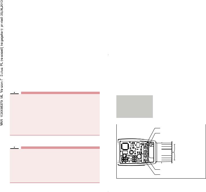
6.3. Forms of the device
6.3.1.Type 8605 Cable plug version
english 9
6.3.2.Type 8605 DIN rail version
|
|
|
|
|
|
|
|
|
|
Fig. 2: Type 8605 DIN rail version |
|
Fig. 1: Type 8605 Cable plug version |
|||
|
|
Plug-in version on valves with connector pattern A (e. g. types 2832, 2833, 2834, 2835, 2836, 2853, 2863, 2865, 2873, 2875, 6022, 6023, 6024, 6223).
The operating unit can be removed after the setting process. During operation of the Control Electronics 8605 in cable plug version without operating unit, the operating status is indicated by two LEDs.
Device variants:
•Variant 1 for valves with a max. current from 200 to 1000 mA
•Variant 2 for valves with a max. current from 500 to 2000 mA
Separate electronics in housing for DIN rail mounting to DIN EN 50022. This form is suitable for all proportional valves in the indicated current range. The operating unit cannot be removed.
Device variants:
•Variant 1 for valves with a max. current from 40 to 220 mA
•Variant 2 for valves with a max. current from 200 to 1000 mA
•Variant 3 for valves with a max. current from 500 to 2000 mA
10 |
english |
|
english |
11 |
|
|
|
|
|
7. TECHNICAL DATA
7.1. Operating Conditions
Power supply |
12...24 V DC ± 10% |
|
Residual ripple 5 % |
Power consumption |
ca. 1 W |
Output current |
|
(on the valve) |
max. 2 A |
Operating temperature |
-10 ... 60 ºC / 14 ...140 ºF |
Interference resistance |
to EN50082-2 |
Emission |
to EN50081-2 |
Current range, depending |
|
on the version for valves |
40 ... 220 mA, |
|
200 ... 1000 mA, |
|
500 ... 2000 mA |
Standard signal input |
|
Voltage (0 ... 5, 0 ... 10 V) |
input impedance > 20 kW |
Current (0 ...20, 4 ... 20 mA) input impedance <200 W
Type 8605
Housing: DIN rail version
Degree of protection |
IP40 (DIN EN 60529) |
Materials |
Polyamide / PBT |
Dimensions |
LxWxH: 97 x 27 x 57 mm |
Housing: Cable plug version |
|
Degree of protection |
IP65 (DIN EN 60529) |
Materials |
Polyamide / PC |
Dimensions |
LxWxH: 70 x 32 x 42.5 mm |
|
|
12 |
english |
|
english |
13 |
|
|
|
||||
|
|
|
|
|
|
|
8. INSTALLATION
8.1. Safety Instructions
 DANGER!
Risk of injury from high pressure in the equipment!
•Before loosening the lines and valves, turn off the pressure and vent the lines.
Risk of injury due to electrical shock!
•Before reaching into the device or the equipment, switch off the power supply and secure to prevent reactivation!
•Observe applicable accident prevention and safety regulations for electrical equipment!
 DANGER!
Risk of injury from improper installation!
•Installation may be carried out by authorised techni cians only and with the appropriate tools!
Risk of injury from unintentional activation of the system and an uncontrolled restart!
•Secure system from unintentional activation.
•Following assembly, ensure a controlled restart.
8.2. Electrical connections
8.2.1.Type 8605 Cable plug version
Type 8605 with cable plug version is connected electrically via a 4-pin terminal strip in the device.
|
Cable diameter |
6 ... 8 mm |
||||||||||
|
|
|
|
|
|
|
|
|
|
|
|
|
|
Cable cross-section |
max. 0.75 mm2 |
||||||||||
|
Cable connections |
Cable gland or plug-in connector |
||||||||||
|
|
|
|
|
|
|
|
M12, 4-pin |
||||
|
|
|
|
|
|
|
|
|
|
|
|
|
|
|
|
|
|
|
|
|
|
|
|
|
|
|
|
|
|
|
|
|
|
Standard signal (+) |
||||
|
|
|
|
|
|
|
|
|
Standard signal (-) |
|||
|
|
|
|
|
|
|
|
|
|
|
|
|
|
|
|
|
|
|
|
|
|
|
|
|
|
|
|
|
|
|
|
|
|
|
|
|
|
|
|
|
|
|
|
|
|
|
|
|
|
|
|
|
|
|
|
|
|
|
|
|
|
|
|
|
|
|
|
|
|
|
|
|
|
|
|
|
|
|
|
|
|
|
|
|
|
|
|
|
|
|
|
|
|
|
|
|
|
|
|
|
|
|
|
|
|
|
|
|
|
|
|
|
|
|
|
|
|
|
|
|
|
|
|
|
|
|
|
|
|
|
|
|
|
|
|
|
|
|
|
|
|
|
GND
12 ... 24 V DC
Fig. 3: Terminal strip connection
14 |
english |
|
english |
15 |
|
|
|
|
|

12 ... 24 V DC |
Standard signal (+) |
GND |
Standard signal (-) |
Type 8605
NOTE!
Ensure proper seating of the valve when screwing onto the valve (cable plug version).
Do not tighten the screw M3 too tightly (max. 0.3 Nm), as otherwise the housing will be deformed and proper operation of the keys will no longer be possible.
Fig. 4: |
Plug connector connection |
8.2.2. LEDs during operation without |
|
|
|
|
|
operating unit |
|
|
|
During operation of the control electronics Type 8605 cable |
||
|
|
plug version without operating unit, the operating status is |
||
|
|
indicated by two LEDs. |
|
|
|
|
|
LED green: Device in operation |
|
|
|
|
LED yellow: Current through valve |
|
|
Tighten screw M3 to max. 0.3 Nm |
|
|
|
Fig. 5: Assembly at the valve |
Fig. 6: |
LEDs for version without operating unit |
|
|
|
|
|
||
16 |
english |
|
english |
17 |
8.2.3.Type 8605 DIN rail version
The electrical connection of Type 8605 DIN rail version is made via terminal strips.
|
Terminal strip |
Cable |
|
|
cross-section |
|
|
|
2-pin |
For valve |
max. 1.5 mm2 |
3-pin |
For RS232 or RS485 interface |
max. 0.5 mm2 |
4-pin |
For voltage supply and |
max. 1.5 mm2 |
|
standard signal |
|
|
|
|
1 |
5 |
|
2 |
6 |
|
3 |
7 |
|
8 |
||
|
||
4 |
9 |
|
Fig. 7: |
Terminal strip connection |
Legend to figure: |
|
|
|
|
|
|
|
|
|
1 |
12 ... 24 V DC |
|
6 |
Valve |
2 |
GND |
|
7 |
RS485-B / TxD |
3 |
Standard signal (-) |
|
8 |
RS485-A / RxD |
4 |
Standard signal (+) |
9 |
GND |
|
5Valve
9.CLEANING
Use the normal cleaning agents to clean the Control Elec tronics, Type 8605. Use no alkaline cleansing agents, as these have a damaging effect on the materials used.
10.PACKAGING, TRANSPORT, STORAGE
NOTE!
Transport damages!
Inadequately protected equipment may be damaged during transport.
•During transportation protect the device against wet and dirt in shock-resistant packaging.
•Avoid exceeding or dropping below the allowable storage temperature.
Incorrect storage may damage the device.
•Store the device in a dry and dust-free location!
•Storage temperature. -40 …+ 55 °C.
18 |
english |
|
english |
19 |
|
|
|
|
|
Type 8605
10.1.Decommissioning
Switch off the Control Electronics Type 8605 as follows: →→Depressurize the system.
→→Switch off the power supply. →→Remove the Control Electronics.
→→Keep the control electronics in the original packaging or in some other suitable packaging.
10.2.Restarting
Switch on the Control Electronics Type 8605 again as follows:
→→Unpack the Control Electronics and allow it to reach room temperature before switching on again.
→→Then proceed as described in chapter “8. Installation”.
11. DISPOSAL
→→Dispose of the device and packaging in an environmen tally friendly manner.
NOTE!
Damage to the environment caused by device components contaminated with media.
•Observe applicable regulations on disposal and the environment.
Observe national waste disposal regulations.
20 english
 Loading...