


Type 8691
Control Head
Steuerkopf
Tête de commande
Quickstart
English Deutsch Français

We reserve the right to make technical changes without notice. Technische Änderungen vorbehalten.
Sous réserve de modifications techniques.
© 2007 - 2013 Bürkert Werke GmbH
Quickstart 1312/04_EU-ML_00806079 / Original DE

Type 8691
Contents
1 |
Quickstart.................................................................................................. |
4 |
|
|
1.1 |
Definition of term / abbreviation............................................. |
4 |
|
1.2 |
Symbols....................................................................................... |
4 |
2 |
Authorized use...................................................................................... |
5 |
|
|
2.1 |
Restrictions................................................................................. |
5 |
3 |
Basic safety instructions.......................................................... |
5 |
|
4 |
General information......................................................................... |
7 |
|
|
4.1 |
Contact address........................................................................ |
7 |
|
4.2 |
Warranty....................................................................................... |
7 |
|
4.3 |
Information on the Internet....................................................... |
7 |
5 |
System description............................................................................ |
7 |
|
|
5.1 |
Structure and function.............................................................. |
7 |
5.2Control head for integrated installation on the 21xx series.
8
5.3Model for control of process valves belonging to the 20xx series 8
6 Technical data......................................................................................... |
9 |
|
6.1 |
Conformity................................................................................... |
9 |
6.2 |
Standards.................................................................................... |
9 |
6.3 |
Operating conditions................................................................ |
9 |
6.4 |
Mechanical data......................................................................... |
9 |
6.5 |
Type label..................................................................................... |
9 |
6.6 |
Pneumatic data......................................................................... |
10 |
6.7 |
Electrical data........................................................................... |
10 |
7 Installation............................................................................................ |
12 |
7.1 Safety instructions................................................................... |
12 |
7.2Installation of the control head on process valves
of series 21xx............................................................................ |
12 |
7.3Installation of the control head on process valves
|
|
of series 20xx............................................................................ |
13 |
8 |
Pneumatic installation................................................................ |
15 |
|
9 |
Electrical installation............................................................... |
16 |
|
|
9.1 |
Safety instructions................................................................... |
16 |
|
9.2 |
Electrical installation 24 V DC.............................................. |
17 |
|
9.3 |
Display elements 24 V DC.................................................... |
19 |
|
9.4 |
Programming data AS-Interface........................................... |
19 |
|
9.5 |
Electrical installation AS-Interface........................................ |
20 |
|
9.6 |
Display elements AS-Interface............................................. |
22 |
|
9.7 |
Electrical installation DeviceNet............................................ |
23 |
|
9.8 |
Display elements DeviceNet................................................ |
25 |
10 |
Teach function.................................................................................... |
27 |
|
|
10.1 |
Starting the teach function.................................................... |
27 |
11 |
Safety positions................................................................................ |
29 |
|
12 |
Accessories........................................................................................... |
29 |
|
13 |
Packaging, Transport, Storage.......................................... |
30 |
|
|
|
|
|
english |
3 |
|
|
|

Type 8691
Quickstart
1Quickstart
The Quickstart describe the entire life cycle of the device. Keep the Quickstart in a location which is easily accessible to every user and make the Quickstart available to every new owner of the device.
Important Safety Information.
Read Quickstart carefully and thoroughly. Study in particular the chapters entitled “Basic safety instructions” and “Authorized use”.
Quickstart must be read and understood.
Quickstart explains, for example, how to install and start-up the device.
A detailed description of the device can be found in the operating instructions for control head Type 8691.
The operating instructions can be found on the enclosed CD and on the Internet at:
www.burkert.com
1.1Definition of term / abbreviation
The term “device” used in these instructions always stands for the control head Type 8691.
In these instructions, the abbreviation “Ex” always refers to “potentially explosive”.
1.2Symbols
The following symbols are used in these instructions.
 Danger!
Warns of an immediate danger.
Failure to observe the warning may result in a fatal or serious injury.
 Warning!
Warns of a potentially dangerous situation.
Failure to observe the warning may result in serious injuries or death.
 Caution!
Warns of a possible danger.
Failure to observe this warning may result in a medium or minor injury.
Note!
Warns of damage to property.
indicates important additional information, tips and recommendations.
refers to information in these operating instructions or in other documentation.
Designates an instruction to prevent risks. →→designates a procedure that must be carried out.
|
|
4 |
english |
|
|
Type 8691
Authorized use
2Authorized use
Non-authorized use of the control head Type 8691 may be a hazard to people, nearby equipment and the environment.
The device is designed to be mounted on pneumatic actuators of process valves for the control of media.
Do not expose the device to direct sunlight.
Use according to the authorized data, operating conditions and conditions of use specified in the contract documents and operating instructions. These are described in the chapter entitled “6 Technical data”.
The device may be used only in conjunction with third-party devices and components recommended and authorized by Bürkert.
In view of the large number of options for use, before installation, it is essential to study and if necessary to test whether the control head is suitable for the actual use planned.
Correct transportation, correct storage and installation and careful use and maintenance are essential for reliable and faultless operation.
Use the control head Type 8691 only as intended.
3Basic safety instructions
These safety instructions do not make allowance for any
•contingencies and events which may arise during the installation, operation and maintenance of the devices.
•local safety regulations – the operator is responsible for observing these regulations, also with reference to the installation personnel.
Risk of injury from high pressure in the equipment/device.
Before working on equipment or device, switch off the pressure and deaerate/drain lines.
Risk of electric shock.
Before working on equipment or device, switch off the power supply and secure to prevent reactivation.
Observe applicable accident prevention and safety regulations for electrical equipment.
2.1Restrictions
If exporting the system/device, observe any existing restrictions.
|
|
|
|
english |
5 |
|
|
|
Type 8691
Basic safety instructions
General hazardous situations.
To prevent injury, ensure:
In the potentially explosion-risk area the control head Type 8691 may be used only according to the specification on the separate approval sticker. For use observe the additional instructions enclosed with the device together with safety instructions for the explosion-risk area.
Devices without a separate approval sticker may not be used in a potentially explosive area.
Installation and repair work may be carried out by authorized technicians only and with the appropriate tools.
After an interruption in the power supply or pneumatic supply, ensure that the process is restarted in a defined or controlled manner.
The device may be operated only when in perfect condition and in consideration of the operating instructions.
The general rules of technology apply to application planning and operation of the device.
To prevent damage to property on the device, ensure:
Do not feed any aggressive or flammable media into the pilot air port.
Do not feed any liquids into the pilot air port.
When unscrewing and screwing in the body casing or the transparent cap, do not hold the actuator of the process valve but the connection housing of Type 8691.
Do not put any loads on the housing (e.g. by placing objects on it or standing on it).
Do not make any external modifications to the device housing. Do not paint the housing parts or screws.
|
|
6 |
english |
|
|
Type 8691
General information
4General information
4.1Contact address
Germany
Bürkert Fluid Control System
Sales Center
Chr.-Bürkert-Str. 13-17
D-74653 Ingelfingen
Tel. + 49 (0) 7940 - 10 91 111
Fax + 49 (0) 7940 - 10 91 448
E-mail: info@de.buerkert.com
International
Contact addresses can be found on the final pages of the printed operating instructions.
And also on the Internet at: www.burkert.com
5System description
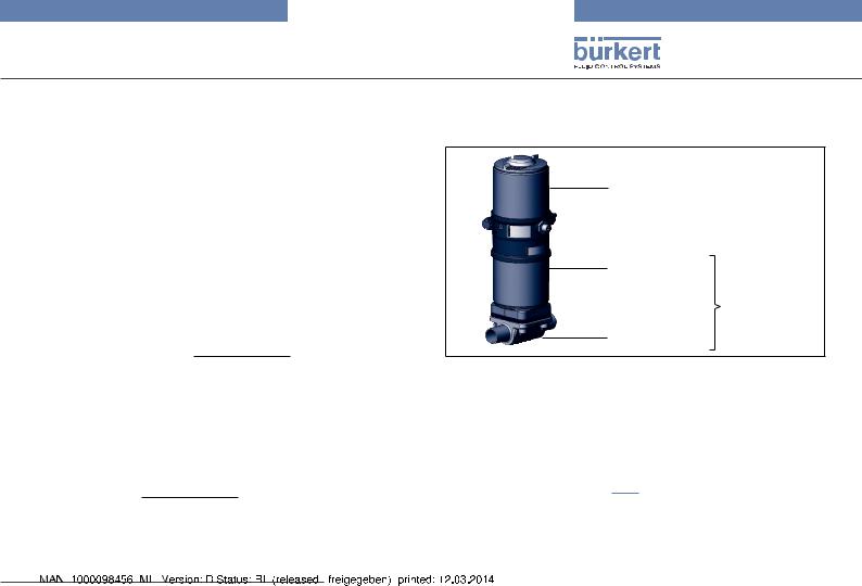
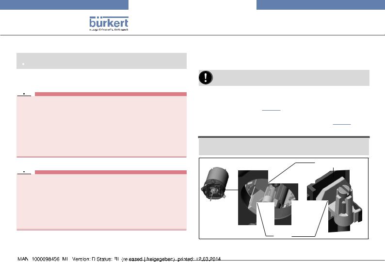
5.1Structure and function
Control head
Actuator
Process valve
Valve body
Fig. 1: Structure
4.2Warranty
The warranty is only valid if the control head Type 8691 is used as intended in accordance with the specified application conditions.
4.3Information on the Internet
The operating instructions and data sheets for Type 8691 can be found on the Internet at: www.burkert.com
The control head Type 8691 can control single or double-acting process valves and has been optimized for the integrated modular fitting of series 21xx process valves (Element) . Various expansion stages are possible thanks to the modular design.
For installation on the 20xx series (Classic) there is a special model which is described in chapter “5.3”.
The valve position is recorded via a contactless, analog sensor element which automatically detects and saves the valve end positions by means of the teach function during start-up.
|
|
|
|
english |
7 |
|
|
|

Type 8691
System description
Apart from the electrical position feedback, the status of the device is optically displayed on the control head itself by a colored highpower LED.
Option: Communication possible via AS-Interface or DeviceNet.
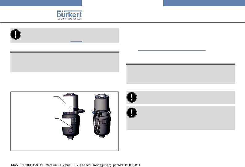
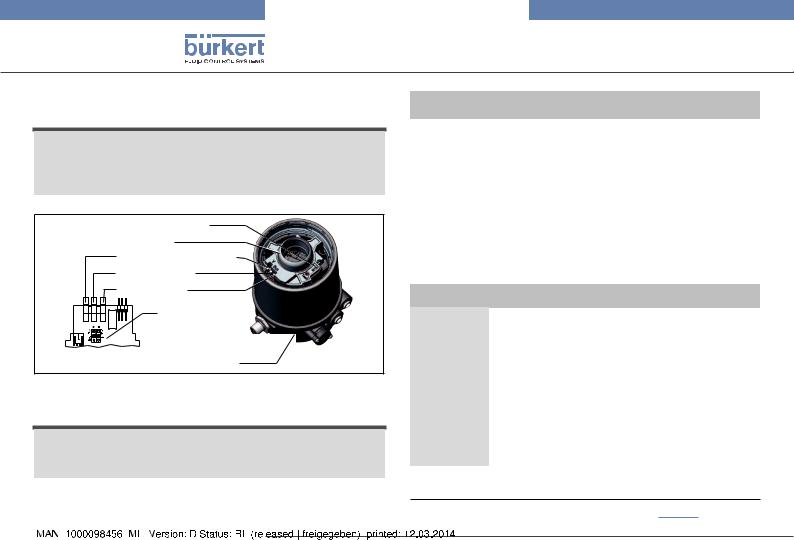
5.2Control head for integrated installation on the 21xx series
|
|
|
|
Electrical connection |
|
|
|
|
|
||||
|
|
|
|
Cable gland |
|
|
|
|
|
||||
|
|
|
|
M16 x 1.5 or |
|
|
|
|
|
||||
|
|
|
|
Circular plug-in |
|
|
|
|
|
||||
|
|
|
|
connector M12 x 1 |
|
|
|
|
|
||||
|
|
|
|
|
Body casing |
|
|
|
|
|
|
|
|
|
|
|
|
|
|
|
|
|
|
|
|
||
|
|
|
|
|
|
|
|
|
|
|
|
|
|
|
|
|
Connection housing |
|
|
|
|
|
|
||||
|
|
|
|
|
|
|
|
|
|||||
|
|
|
|
|
|
|
|
|
|||||
Air intake filter |
|
|
|
|
|
|
|
|
|||||
|
|
|
|
|
|
Pressure limiting valve |
|
||||||
View without transparent cap |
(for protection against too |
|
|||||||||||
|
|
|
|
|
|
high internal pressure in |
|
||||||
|
|
|
|
Top LEDs |
case of error) |
|
|||||||
|
|
|
|
Exhaust air port |
|
||||||||
|
|
|
|
|
|||||||||
|
|
|
|
Teach function |
|
||||||||
|
|
|
|
|
|
(label: 3) |
|
||||||
|
|
|
|
|
|
|
|||||||
|
|
|
|
|
|
|
|
|
|
|
|
||
|
|
|
|
|
|
|
|
|
|
|
Pilot air port |
||
|
|
|
|
|
|
|
|
|
|
|
|
(label: 1) |
|
|
|
|
|
|
|
|
|
|
|
|
|
||
Fig. 2: Structure for process valves belonging to the 21xx series |
|||||||||||||
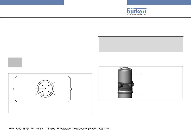
5.3Model for control of process valves belonging to the 20xx series
A special model enables the control head Type 8691 to be attached to process valves belonging to the 20xx series.
This model features has a different connection housing so that the pilot air ports can be connected to the outside of the actuator (see “Fig. 3”).
Pilot air outlet 21
Pilot air outlet 22
Fastening screws (2 x) 
Connection housing
Fig. 3: Structure for process valves belonging to the 20xx series
|
|
8 |
english |
|
|
Type 8691
Technical data
6Technical data
6.1Conformity
In accordance with the EC Declaration of conformity, the control head Type 8691 is compliant with the EC Directives.
6.2Standards
The applied standards on the basis of which compliance with the EC Directives is confirmed are listed in the EC type examination certificate and/or the EC Declaration of Conformity.
6.3Operating conditions
 Warning!
Solar radiation and temperature fluctuations may cause malfunctions or leaks.
If the device is used outdoors, do not expose it unprotected to the weather conditions.
Ensure that the permitted ambient temperature does not exceed the maximum value or drop below the minimum value.
Ambient temperature |
see type label |
|||
Degree of protection |
IP65 / IP67 according to EN 60529 |
|||
|
(only if cables, plugs and sockets have |
|||
|
been connected correctly |
|||
|
and in compliance with the exhaust |
|||
|
air concept in chapter “8 Pneumatic |
|||
|
installation”). |
|
|
|
|
|
|
|
|
6.4Mechanical data
Dimensions |
see data sheet |
|
Housing material |
exterior: |
PPS, PC, VA |
Sealing material |
exterior: |
EPDM |
|
interior: |
NBR |
Stroke range of valve spindle: |
2 – 28 mm |
|
|
2 – 47 mm |
|
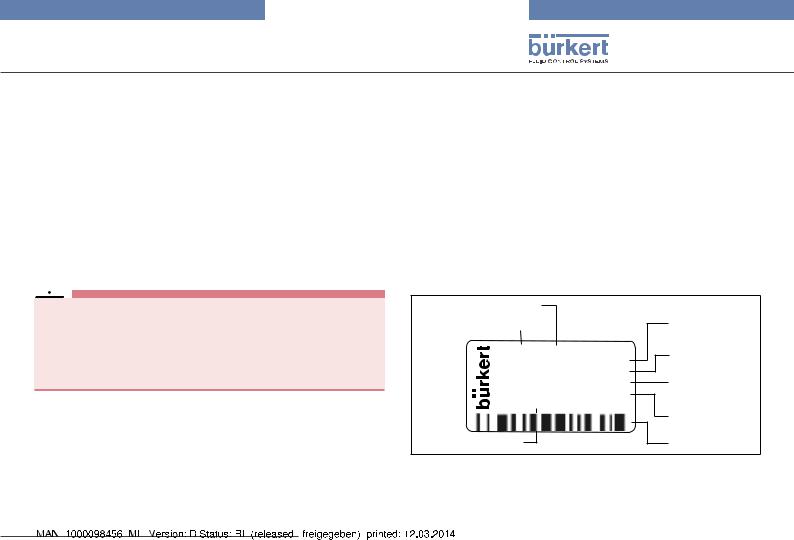
6.5Type label
Example:
Supply voltage / Control
|
Typ |
|
|
|
|
|
8691 AS-i 62SI |
|
|||
|
Ingelfingen |
|
|||
|
|
||||
|
single act |
Pilot 3,0 |
|
||
|
|
Pmax 7bar |
|
|
|
|
D-74653 |
Tamb 0°C - +55°C |
CE |
||
|
Ser.-Nr. 001000 |
||||
|
00179024 |
W14UN |
|
||
|
|
|
|||
Identification number
Fig. 4: Type label (example)
Control function - Pilot valve
Max. operating pressure
Max. ambient temperature
Serial number - CE mark
Bar-code
|
|
|
|
english |
9 |
|
|
|

Type 8691
Technical data
6.6Pneumatic data
Control medium |
|
neutral gases, air |
Quality classes in accordance with DIN ISO 8573-1 |
||
Dust content |
Class 5 |
max. particle size 40 µm, |
|
|
max. particle density 10 mg/m³ |
Water content |
Class 3 |
max. pressure dew point |
|
|
- 20 °C or min. 10 °C below the |
|
|
lowest operating temperature |
Oil content |
Class 5 |
max. 25 mg/m³ |
Temperature range |
|
|
control medium |
|
-10 – +50 °C |
Pressure range |
|
|
control medium |
|
3 – 7 bar |
Air output of pilot valve |
250 lN / min |
|
|
|
(for aeration and deaeration) |
|
|
(QNn - value according to definition for |
|
|
pressure drop from 7 to 6 bar absolute) |
Connections |
|
Plug-in hose connector 6 mm / 1/4“ |
|
|
Socket connection G 1/8 |
6.7Electrical data
6.7.1Electrical data without bus control 24 V DC
Connections |
Cable gland M16 x 1.5, wrench size 22 |
|
(clamping area 5 – 10 mm) |
|
with screw-type terminals for cable cross- |
|
sections 0.14 – 1.5 mm² |
|
Circular plug-in connector |
|
(M12 x 1, 8-pole) |
Pilot valve |
|
Supply voltage |
24 V DC ± 10% |
|
max. residual ripple 10 % |
Power input |
max. 1 W |
Output |
max. 100 mA per output |
Display |
max. 20 mA per illustrated illuminated |
|
display (LED) |
|
|
10 |
english |
|
|
Type 8691
Technical data
6.7.2Electrical data with AS-Interface bus control
Connections |
Circular plug-in connector |
|
(M12 x 1, 4-pole) |
Supply voltage |
29.5 V – 31.6 V DC |
|
(according to specification) |
Outputs |
|
Max. switching capacity |
1 W via AS-Interface |
Watchdog function |
integrated |
Devices without external supply voltage
6.7.3Electrical data with DeviceNet bus control
Connections |
Circular plug-in connector |
|
(M12 x 1, 5-pole) |
Supply voltage |
11 V – 25 V |
Max. power consumption |
< 80 mA |
Output |
≤ 50 mA |
Pull-in current current |
|
Holding current |
≤ 30 mA |
Max. power consumption |
120 mA |
Power consumption input during |
|
normal operation |
|
(after current reduction; |
|
valve + 1 end position reached) |
90 mA |
Devices with external supply voltage |
|
External supply voltage |
24 V ± 10 % |
The power supply unit must include a secure disconnection in accordance with IEC 364-4-41 (PELV or SELV)
Max. power consumption |
55 mA (after current reduction |
|
≤ 30 mA) |
Max. power consumption |
|
from AS-Interface |
55 mA |
|
|
|
|
english |
11 |
|
|
|
Type 8691
Installation
7Installation
 Only for control head without pre-assembled process valve.
7.1Safety instructions
 DANGER!
Risk of injury from high pressure in the equipment/device.
Before working on equipment or device, switch off the pressure and deaerate/drain lines.
Risk of electric shock.
Before working on equipment or device, switch off the power supply and secure to prevent reactivation.
Observe applicable accident prevention and safety regulations for electrical equipment.
 Warning!
Risk of injury from improper installation.
Installation may be carried out by authorized technicians only and with the appropriate tools.
Risk of injury from unintentional activation of the system and an uncontrolled restart.
Secure system from unintentional activation.
Following assembly, ensure a controlled restart.
7.2Installation of the control head on process valves of series 21xx
Procedure:
When the control head is being installed, the collets of the pilot air ports must not be fitted to the actuator.
→→Align the puck and the control head until
1.the puck can be inserted into the guide rail of the control head (see “Fig. 5”) and
2.the connection pieces of the control head can be inserted into the pilot air ports of the actuator (see also “Fig. 6”).
Note!
Damaged printed circuit board or malfunction.
Ensure that the puck is situated flat on the guide rail.
Guide rail
Puck
Fig. 5: Aligning the puck
|
|
12 |
english |
|
|

Type 8691
Installation
→→Push the control head, without turning it, onto the actuator until no gap is visible on the form seal.
Note!
Too high torque when screwing in the fastening screw does not ensure degree of protection IP65 / IP67.
The fastening screws may be tightened to a maximum torque of 0.5 Nm only.
→→Attach the control head to the actuator using the two side fastening screws. In doing so, tighten the screws only hand-tight (maximum torque: 0.5 Nm).
Connection |
|
|
pieces |
|
|
|
|
|
|
|
|
Pilot air ports |
|
Fastening |
|
||
|
|
screws |
max. 0.5 Nm
Actuator
Fig. 6: Installation of control head, 21xx series
7.3Installation of the control head on process valves of series 20xx
Procedure:
Guide rail
Puck
Fig. 7: Aligning the puck
→→Push the control head onto the actuator. The puck must be aligned in such a way that it is inserted into the guide rail of the control head (see “Fig. 7”).
Note!
Damaged printed circuit board or malfunction.
Ensure that the puck is situated flat on the guide rail.
→→Press the control head all the way down as far as the actuator and turn it into the required position.
|
|
|
|
english |
13 |
|
|
|
Type 8691
Installation
Ensure that the pneumatic connections of the control head and those of the valve actuator are situated preferably vertically one above the other (see “Fig. 8”).
Note!
Too high torque when screwing in the fastening screw does not ensure degree of protection IP65 / IP67.
The fastening screws may be tightened to a maximum torque of 0.5 Nm only.
→→Attach the control head to the actuator using the two side fastening screws. In doing so, tighten the fastening screws handtight only (maximum torque: 0.5 Nm).
→→Screw the plug-in hose connectors onto the control head and the actuator.
→→Using the hoses supplied in the accessory kit, make the pneumatic connection between the control head and actuator with the “Tab. 1: Pneumatic connection to actuator”.
Note!
Damage or malfunction due to ingress of dirt and moisture.
To comply with degree of protection IP65 / IP67, connect the pilot air outlet (only for CFA or CFB) which is not required to the free pilot air port of the actuator or seal with a plug.
Pilot air outlet 21
Pilot air outlet 22 
Upper pilot air port
Lower pilot air port 
Example
80, CFA
Fig. 8: Installing the pneumatic connection, 20xx series
“In rest position” means that the pilot valves of the control head Type 8691 are isolated or not actuated.
If the ambient air is humid, a hose can be connected between pilot air outlet 22 of the control head and the unconnected pilot air port of the actuator for control function A or control function B. As a result, the spring chamber of the actuator is supplied with dry air from the vent duct of the control head.
|
|
14 |
english |
|
|

Type 8691
Pneumatic installation
Control function A (CFA) |
|
|
|
|
|
Process valve closed in rest position (by spring force) |
|
|
|||
Control |
Pilot air outlet |
22 |
21 |
22 |
21 |
head |
|
|
|
|
|
Actuator |
Upper pilot air port |
|
or |
|
|
|
|
|
|
||
Lower pilot air port |
|
|
|
|
|
|
|
|
|
|
|
Control function B (CFB)
Process valve open in rest position (by spring force)
Control |
Pilot air outlet |
22 |
21 |
22 |
21 |
head |
|
|
|
|
|
Actuator |
Upper pilot air port |
|
|
or |
|
|
|
|
|
||
Lower pilot air port |
|
|
|
|
Control function I (CFI) |
|
|
|
|
|
Process valve in rest position |
|
closed |
open |
|
|
Control |
Pilot air outlet |
22 |
21 |
22 |
21 |
head |
|
|
|
|
|
Actuator |
Upper pilot air port |
|
|
|
|
Lower pilot air port |
|
|
|
|
|
|
|
|
|
|
|
Tab. 1: Pneumatic connection to actuator |
|
|
|||
8Pneumatic installation
 DANGER!
Risk of injury from high pressure in the equipment/device.
Before working on equipment or device, switch off the pressure and deaerate/drain lines.
Procedure:
→→Connect the control medium to the pilot air port (1) (3 – 7 bar; instrument air, free of oil, water and dust).
→→Attach the exhaust airline or a silencer to the exhaust air port (3) (see “Fig. 9: Pneumatic connection”).
Keep the adjacent supply pressure always at least 0.5 – 1 bar above the pressure which is required to move the actuator to its end position.
Important information for the problem-free functioning of the device:
The installation must not cause back pressure to build up.
Select a hose for the connection with an adequate cross-section.
The exhaust air line must be designed in such a way that no water or other liquid can get into the device through the exhaust air port.
|
|
|
|
english |
15 |
|
|
|

Type 8691
Electrical installation
Pilot air port (label: 1)
Exhaust air port (label: 3)
Fig. 9: Pneumatic connection
Caution: (Exhaust air concept):
In compliance with degree of protection IP67, an exhaust air line must be installed in the dry area.
9Electrical installation
9.1Safety instructions
 DANGER!
Risk of electric shock.
Before working on equipment or device, switch off the power supply and secure to prevent reactivation.
Observe applicable accident prevention and safety regulations for electrical equipment.
 Warning!
Risk of injury from improper installation.
Installation may be carried out by authorized technicians only and with the appropriate tools.
Risk of injury from unintentional activation of the system and an uncontrolled restart.
Secure system from unintentional activation.
Following installation, ensure a controlled restart.
|
|
16 |
english |
|
|

Type 8691
Electrical installation
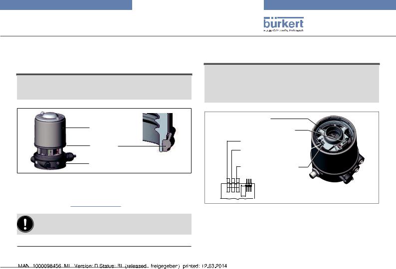
9.2Electrical installation 24 V DC
9.2.1 Electrical installation with cable gland
Note!
Breakage of the pneumatic connection pieces due to rotational impact.
When unscrewing and screwing in the body casing, do not hold the actuator of the process valve but the connection housing.
→→Unscrew the body casing (stainless steel) in a counter-clockwise direction.
Body casing
Connection housing
Actuator
Fig. 10: Open control head
→→Push the cables through the cable gland. →→Connect the wires.
|
Jumper: assignment p-n-p or n-p-n |
|
|
|
outlet (optional) |
|
IN 1 = Top (top) |
|
|
IN 2 = Bot (bottom) |
|
|
Screw terminals |
IN 1 |
|
end positions |
IN 2 |
|
|
|
|
Screw terminals |
+ |
|
Supply 24 V DC |
24 V- |
|
Screw terminals |
+ |
|
Valve (control) |
Valve |
|
- |
|
|
Jumper: |
|
|
Color assignment of the Top LEDs |
|
Fig. 11: |
Connection with cable gland |
|
|
|
|
|
english |
17 |
|
|
|
Type 8691
Electrical installation
Body casing
Seal
body casing
Connection housing
Fig. 12: Position of the seal in the body casing
→→Tighten union nut on the cable gland (torque approx. 1.5 Nm). →→Check that the seal is correctly positioned in the body casing. →→Close the device (assembly tool: 6740771)).
Note!
Damage or malfunction due to penetration of dirt and humidity.
To ensure degree of protection IP65 / IP67:
Tighten the union nut on the cable gland according to the cable size or dummy plugs used. (ca. 1,5 Nm).
Screw the body casing in all the way.
The teach function can now be used to automatically determine and read in the end positions of the valve (description of the teach function see chapter “10 Teach function”).
1) The assembly tool (674077) is available from your Bürkert sales office.
9.2.2Electrical installation 24 V DC with circular plug-in connector
→→Connect the control head according to the table.
The teach function can now be used to automatically determine and read in the end positions of the valve (description of the teach function see chapter “10 Teach function”).
|
|
6 |
5 |
|
|
4 |
|
|
|
|
|
|
|
|
|||
|
|
7 |
|
|
|
|
3 |
|
|
|
8 |
|
|
|
|
|
|
|
|
|
|
2 |
||||
|
|
|
|
|
|
|||
|
|
1 |
|
|
|
|
||
|
|
|
|
|
|
|
|
|
|
|
|
|
|
|
|
|
|
Fig. 13: Circular plug M12 x 1, 8-pole |
|
|
|
|
||||
|
|
|
|
|
|
|
||
Pin |
Wire color2) |
Designation |
|
|
|
Configuration |
||
1 |
white |
Limit switch top |
|
|
|
IN 1 (=Top) |
||
2 |
brown |
Limit switch bottom |
|
|
IN 2 (=Bot) |
|||
3 |
green |
Supply voltage |
|
|
|
GND |
||
4 |
yellow |
Supply voltage + |
|
|
|
24 V DC |
||
5 |
grey |
Valve control unit + |
|
|
Valve + |
|||
6 |
pink |
Valve control unit - |
|
|
|
Valve - |
||
7 |
|
- |
|
|
|
|
|
not used |
8 |
|
- |
|
|
|
|
|
not used |
Tab. 2: |
Connection with circular plug-in connector |
|||||||
2)The indicated colors refer to the connecting cable available as an accessory (919061).
|
|
18 |
english |
|
|

Type 8691
Electrical installation
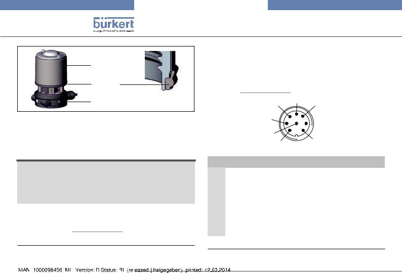
9.3Display elements 24 V DC
Note!
Breakage of the pneumatic connection pieces due to rotational impact.
When unscrewing and screwing in the transparent cap, do not hold the actuator of the process valve but the connection housing.
Top LEDs
Status LED (yellow)
LED pilot valve (yellow) Connection housing
Fig. 14: Display elements 24 V DC
LED |
Color |
|
|
|
|
Top LEDs3) |
is lit green |
End postion bottom |
|
is lit yellow |
End postion top |
LED Pilot valve |
is lit yellow |
Pilot valve is actuated |
Status LED |
flashing yellow |
Teach function is running |
|
flickers yellow |
Puck PCB not available |
Tab. 3: Display elements 24 V DC
Note!
Damage or malfunction due to penetration of dirt and humidity.
To observe degree of protection IP65 / IP67, screw the transparent cap in all the way.
9.4Programming data AS-Interface
|
AS-Interface |
AS-Interface |
|
31 slaves |
62 slaves |
I/O configuration |
B hex (1 input, 2 outputs) |
|
|
|
|
ID code |
F hex |
A hex |
|
|
|
Extended ID code 1 |
F hex |
7 hex |
|
|
|
Extended ID code 2 |
F hex |
E hex |
|
|
|
Profile |
S-B.F.F |
S-B.A.E |
|
|
|
Tab. 4: Programming data
3)Color setting ex works. Can be set via jumper (see “Fig. 11: Connection with cable gland”).
|
|
|
|
english |
19 |
|
|
|
Type 8691
Electrical installation
9.5Electrical installation AS-Interface
9.5.1Connection with circular plug-in connector M12 x 1, 4-pole, male
Connector views
The views show the image from the front looking at the pins, the solder connections are behind them.
Pin 4: |
Pin 3: |
NC |
Bus – |
Pin 1: |
Pin 2: |
Bus + |
NC |
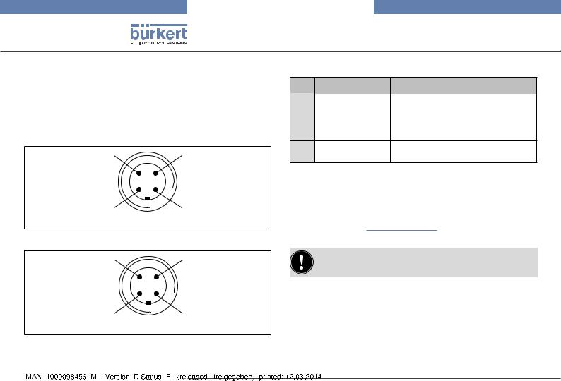
Bus connection without external / with external supply voltage
Pin |
Designation |
Configuration |
|
|
|
|
|
1 |
Bus + |
AS-Interface bus line + |
|
2 |
NC or GND |
not used or external supply voltage – |
|
(optional) |
(optional) |
||
|
|||
3 |
Bus – |
AS-Interface bus line – |
4NC or 24 V + not used or external supply voltage + (optional) (optional)
Tab. 5: Pin assignment of circular plug-in connector for AS-Interface
→→Connect the control head according to the table.
The teach function can now be used to automatically determine and read in the end positions of the valve (description of the teach function see chapter “10 Teach function”).
Fig. 15: Bus connection without external supply voltage
Pin 4: |
Pin 3: |
24 V + |
Bus – |
Pin 1: |
Pin 2: |
Bus + |
GND |
For the bus variant AS-Interface, the teach function can also be started via the bus protocol.
Fig. 16: Bus connection with external supply voltage (optional)
|
|
20 |
english |
|
|
Type 8691
Electrical installation
9.5.2Connection with multi-pole cable and ribbon cable terminal
As an alternative to the bus connection model with 4-pole circular plug, there is the control head with multi-pole cable (M12 circular plug) and ribbon cable terminal. The wiring diagram of the circular plug corresponds to the bus connection of the M12 4-pole circular plug and can easily be connected to the ribbon cable terminal (see “Fig. 17”).
 Screws
M12 plug-in connector branch circuit
Fig. 17: Control head 8691 with multi-pole cable and ribbon cable terminal
Handling the ribbon cable terminal
The multi-pole cable features a ribbon cable terminal - with M12 plug-in connector branch circuit - for AS-Interface cable harness. The ribbon cable terminal contacts the AS-Interface cable harness by means of penetration technology which allows installation by “clipping in” the ASInterface cable harness without cutting and without removing insulation.
Procedure:
→→Open the ribbon cable terminal (loosen screws and remove cover)
→→Insert cable harness conclusively →→Close ribbon cable terminal again
→→Tighten screws
Slightly undo thread-forming screws
(approx. 3/4 turn to the left) and position them on the existing tapped bore and screw in.
The teach function can now be used to automatically determine and read in the end positions of the valve (description of the teach function see chapter “10 Teach function”).
For the bus variant AS-Interface, the teach function can also be started via the bus protocol.
|
|
|
|
english |
21 |
|
|
|
Type 8691
Electrical installation
9.6Display elements AS-Interface
Note!
Breakage of the pneumatic connection pieces due to rotational impact.
When unscrewing and screwing in the transparent cap, do not hold the actuator of the process valve but the connection housing.
Status LED yellow
Top LEDs
Pilot valve LED yellow
Bus LED green
Bus LED red
Jumper: Color
assignment of
the Top LEDs
Connection housing
Fig. 18: Display elements AS-Interface
Note!
Damage or malfunction due to penetration of dirt and humidity.
To observe degree of protection IP65 / IP67, screw the transparent cap in all the way.
Bus LED |
|
Bus LED |
|
|
||
(green) |
|
|
(red) |
|
|
|
off |
|
|
off |
POWER OFF |
|
|
|
|
|
|
|
|
|
off |
|
|
on |
No data traffic (expired Watch Dog at slave |
||
|
|
address does not equal 0) |
||||
|
|
|
|
|
||
on |
|
|
off |
OK |
|
|
|
|
|
|
|
|
|
flashing |
|
|
on |
Slave address equals 0 |
||
|
|
|
|
|
|
|
off |
|
|
flashing |
Sensor supply overloaded or external reset |
||
|
|
|
|
|
|
|
flashing |
|
|
flashing |
Teach function error (Periphery error) |
||
|
|
|
|
|
|
|
Tab. 6: |
Display elements bus status |
|
||||
|
|
|
|
|
|
|
LED |
|
|
|
Color |
|
|
|
|
|
||||
Status LED |
flashing yellow |
Teach function is running |
||||
|
|
|
|
flickers yellow |
Puck PCB not available |
|
|
|
|
|
|||
Top LEDs4) |
|
is lit green |
End postion bottom |
|||
|
|
|
|
is lit yellow |
End postion top |
|
|
|
|
|
flashing red |
no data traffic or |
|
|
|
|
|
alternately with the |
||
|
|
|
|
teach function error |
||
|
|
|
|
green or yellow |
||
|
|
|
|
|
||
LED |
|
|
|
is lit yellow |
Pilot valve is actuated |
|
Pilot valve |
|
|||||
|
|
|
|
|||
Tab. 7: |
Display elements AS-Interface |
|
||||
4) Color setting ex works. Can be set via jumper (see “Fig. 18”).
|
|
22 |
english |
|
|
Type 8691
Electrical installation
9.7Electrical installation DeviceNet
9.7.1Bus connection (circular connector M12 x 1, 5-pole, male)
The control head features a 5-pole micro-style circular connector. The following configuration conforms to the DeviceNet specification.
→→Connect the control head according to the table.
Pin |
1 |
2 |
3 |
4 |
5 |
|
|
|
|
|
|
Signal |
Shielding |
V + |
V – |
CAN_H |
CAN_L |
|
|
|
|
|
|
Tab. 8: Pin assignment circular plug-in connector DeviceNet
Data lines
Pin 4: CAN_H
white 
Pin 5: CAN_L
blue
Pin 1: Drain
(Shield)
Pin 3: V– black
Pin 2: V+ |
Supplyvoltage |
–1125 V DC |
|
|
|
red |
|
|
max. power 3 W, if valve is switched
Fig. 19: View of plug from the front onto the pins, the soldered connections are behind
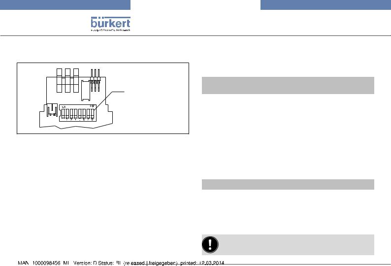
9.7.2 Configuring the control head Setting the DIP switches
Note!
Breakage of the pneumatic connection pieces due to rotational impact.
When unscrewing and screwing in the body casing, do not hold the actuator of the process valve but the connection housing.
→→Unscrew the body casing (stainless steel) in a counter-clockwise direction.
Body casing
Connection housing
Actuator
Fig. 20: Open control head
|
|
|
|
english |
23 |
|
|
|
Type 8691
Electrical installation
→→Set the DIP switches according to the following tables.
DIP switches for bus address and baudrate
Fig. 21: DIP switches DeviceNet
8 DIP switches are available for configuration:
Settings of the DeviceNet address
MAC ID – Medium Access Control Identifier: [DIP 1=off=0 / DIP 1=on=1 /
MAC ID=DIP 1*20+DIP 2*21+...+DIP 6*25]
DIP 1 |
|
DIP 2 |
DIP 3 |
DIP 4 |
DIP 5 |
DIP 6 |
MAC ID |
[20=1] |
|
[21=2] |
[22=4] |
[23=8] |
[24=16] |
[25=32] |
|
|
|
|
|
|
|
|
|
off |
|
off |
off |
off |
off |
off |
0 |
|
|
|
|
|
|
|
|
on |
|
off |
off |
off |
off |
off |
1 |
|
|
|
|
|
|
|
|
off |
|
on |
off |
off |
off |
off |
2 |
|
|
|
|
|
|
|
|
... |
|
... |
... |
... |
... |
... |
... |
|
|
|
|
|
|
|
|
off |
|
on |
on |
on |
on |
on |
62 |
|
|
|
|
|
|
|
|
on |
|
on |
on |
on |
on |
on |
63 |
|
|
|
|
|
|
|
|
Tab. 9: |
Settings of the DeviceNet address |
|
|
||||
• |
DIP switches 1 to 6 |
for the DeviceNet address |
• |
DIP switches 7 to 8 |
for the baudrate |
Setting the baudrate
Adjusting the control head to the baudrate of the network.
DIP 7 |
DIP 8 |
Baudrate |
|
|
|
off |
off |
125 kBaud |
on |
off |
250 kBaud |
off |
on |
500 kBaud |
on |
on |
not permitted |
Tab. 10: Setting the baudrate
If the settings are changed by actuating the DIP switches, this change will not take effect until the device is restarted.
|
|
24 |
english |
|
|
Type 8691
Electrical installation
→→Check that the seal is correctly positioned in the body casing. →→Close the device (assembly tool: 6740775)).
Note!
Damage or malfunction due to penetration of dirt and humidity.
To observe degree of protection IP65 / IP67, screw the body casing in all the way.
Body casing
Seal
body casing
Connection housing
Fig. 22: Position of the seal in the body casing
The teach function can now be used to automatically determine and read in the end positions of the valve (description of the teach function see chapter “10 Teach function”).
For the bus variant DeviceNet, the teach function can also be started via the bus protocol.
5) The assembly tool (674077) is available from your Bürkert sales office.
9.8Display elements DeviceNet
Note!
Breakage of the pneumatic connection pieces due to rotational impact.
When unscrewing and screwing in the transparent cap, do not hold the actuator of the process valve but the connection housing.
Top LEDs
Status LED (yellow)  Pilot valve LED (yellow)
Device status LED (two- coloured: red/green)
Bus status LED (twocoloured: red/green)
Connection housing 
Fig. 23: LED display, DeviceNet
The device status of the control head (transparent cap) is displayed optically by colored high-power LEDs (Top LEDs). The assignment of the green and yellow Top LEDs to the end position can be changed via Explicit Messages (attribute address: class 150, instance 1, attribute 9).
|
|
|
|
english |
25 |
|
|
|
Type 8691
Electrical installation
LED |
Color |
|
|
|
|
|
|
Status LED |
flashing yellow |
Teach function is running |
|
|
flickers yellow |
Puck PCB not available |
|
|
|
|
|
Top LEDs6) |
is lit green |
End postion bottom |
|
|
is lit yellow |
End postion top |
|
|
flashing red |
• Online, without con- |
|
|
nection to the Master |
||
|
alternately with the |
• Connection time-out |
|
|
green or yellow |
||
|
• Critical error |
||
|
|
||
LED |
is lit yellow |
Pilot valve is actuated |
|
Pilot valve |
|||
|
|
||
Tab. 11: Display elements DeviceNet |
|
||
Note!
Damage or malfunction due to penetration of dirt and humidity.
To observe degree of protection IP65 / IP67, screw the transparent cap in all the way.
6) Color setting ex works.
Status of the bus status LED
LED |
Device status |
Explanation |
Troubleshooting |
|
|
|
|
|
|
|
|
Device is not supplied |
Connect other devices, |
|
|
|
with voltage |
||
|
No power |
Device has still not |
if the device is the only |
|
|
network subscriber, |
|||
|
ended Duplicate MAC |
|||
Off |
supply / |
Replace device |
||
ID Test (test lasts |
||||
|
not online |
|||
|
approx. 2 sec) |
Check baud rate |
||
|
|
|||
|
|
Device cannot end |
Check bus connection |
|
|
|
Duplicate MAC ID Test. |
|
|
|
|
|
|
|
|
Online, con- |
Normal operating status |
|
|
Green |
nection to |
with established con- |
|
|
|
master exists |
nection to the master |
|
|
|
|
|
|
|
Flashes |
Online, without |
Normal operating status |
|
|
without established |
|
|||
green |
connection to |
connection to the |
|
|
master |
|
|||
|
master |
|
||
|
|
|
||
|
|
|
|
|
|
|
|
New connection estab- |
|
Flashes |
Connection |
One or more I/O con- |
lishment by master to |
|
nections are in Time- |
ensure that the I/O |
|||
red |
time-Out |
|||
Out state |
data is transmitted |
|||
|
|
|||
|
|
|
cyclically. |
|
|
|
|
|
|
|
|
Another device with the |
|
|
|
|
same MAC ID address |
Check baud rate |
|
|
|
is in the circuit |
||
Red |
Critical fault |
If required, replace |
||
No bus connection |
||||
|
|
device |
||
|
|
due to communication |
||
|
|
|
||
|
|
problems |
|
|
|
|
|
|
|
Tab. 12: Status of the bus status LED |
|
|||
|
|
26 |
english |
|
|

Type 8691
Teach function
Status of the device status LED
LED |
Device status |
Explanation |
|
|
|
Off |
No supply |
Device is not supplied with voltage |
|
|
|
Green |
Device is working |
Normal operating status |
|
|
|
Tab. 13: Status of the device status LED
10 Teach function
The teach function can be used to automatically determine and read in the end positions of the valve.
For the bus variant AS-Interface and DeviceNet, the teach function can also be started via the bus protocol.
10.1 Starting the teach function
Necessary requirements:
Before you can actuate the teach function, you must
•mount the control head on the actuator,
•connect the supply voltage,
•connect the compressed-air supply,
•AS-Interface: pilot valve OFF (D0 = 0),
•the DeviceNet must be connected to the Master (bus LED must be lit green).
|
|
|
|
english |
27 |
|
|
|
 Loading...