


8694
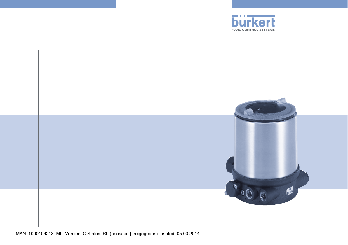
Type 8694
Positioner TopControl Basic
Electropneumatic position controller
Elektropneumatischer Stellungsregler
Positionneur électropneumatique
Quickstart
English Deutsch Français
We reserve the right to make technical changes without notice.
Technische Änderungen vorbehalten.
Sous réserve de modifications techniques.
© 2008-2014 Bürkert Werke GmbH
Operating Instructions 1403/03_EU-ML_00805912 / Original DE
Type 8694
Table of Contents
1. QUICKSTART
1.1. Definition of term “Device” .............................................................4
1.2. Symbols ..............................................................................................4
2. AUTHORIZED USE .........................................................................................5
2.1. Restrictions ........................................................................................5
3. BASIC SAFETY INSTRUCTIONS .............................................................5
4. GENERAL INFORMATION ...........................................................................7
4.1. Contact address ............................................................................... 7
4.2. Warranty ............................................................................................. 7
4.3. Information on the internet .............................................................7
5. STRUCTURE AND FUNCTION..................................................................7
6. TECHNICAL DATA ...........................................................................................8
6.1. Conformity .........................................................................................8
6.2. Standards ........................................................................................... 8
6.3. Operating conditions ....................................................................... 8
6.4. Mechanical data ...............................................................................9
6.5. Type label .......................................................................................... 9
6.6. Pneumatic data ................................................................................. 9
6.7. Electrical data..................................................................................10
6.8. Factory settings of the positioner ...............................................11
.....................................................................................................4
7. INSTALLATION
7.1. Safety instructions .........................................................................11
7.2. Installing the positioner on process valves belonging
to series 2103 and 23xx ..............................................................12
7.3. Installing the positioner on process valves belonging
to series 26xx and 27xx .................................................................... 13
8. FLUID INSTALLATION ................................................................................15
8.1. Safety instructions .........................................................................15
8.2. Installing the process valve ..........................................................15
8.3. Pneumatic connection of the positioner ...................................15
9. ELECTRICAL INSTALLATION .................................................................. 16
9.1. Safety instructions .........................................................................16
9.2. Electrical installation 24 V DC ....................................................16
9.3. Electrical installation AS Interface ...............................................18
10. START-UP ...................................................................................................... 19
10.1. Safety instructions .......................................................................19
10.2. Automatic adjustment X.TUNE ........................................... 19
10.3. Control and display elements....................................................21
11. SAFETY POSITIONS ................................................................................24
12. ACCESSORIES
13. PACKAGING, TRANSPORT, STORAGE .......................................... 25
............................................................................................... 11
...........................................................................................25
english
3
Type 8694
Quickstart
1. QUICKSTART
The operating instructions describe the entire life cycle of the device.
Keep these instructions in a location which is easily accessible to
every user and make these instructions available to every new owner
of the device.
Important Safety Information!
Read Quickstart carefully and thoroughly. Study in particular the
chapters entitled “Basic safety instructions” and “Authorized use”.
• Quickstart must be read and understood.
Quickstart explains, for example, how to install and start-up the
device.
A detailed description of the device can be found in the operating
instructions for positioner Type 8694.
The operating instructions can be found on the enclosed CD
and on the Internet at:
www.burkert.com
1.1. Definition of term “Device”
The term “device” used in these instructions always stands for the
positioner Type 8694.
1.2. Symbols
The following symbols are used in these instructions.
DANGER!
Warns of an immediate danger!
• Failure to observe the warning may result in a fatal or serious
injury.
WARNING!
Warns of a potentially dangerous situation!
• Failure to observe the warning may result in serious injuries or
death.
CAUTION!
Warns of a possible danger!
• Failure to observe this warning may result in a medium or minor
injury.
NOTE!
Warns of damage to property!
indicates important additional information, tips and
recommendations.
refers to information in these operating instructions or in
other documentation.
→ designates a procedure that must be carried out.
4
english
Type 8694
Authorized use
2. AUTHORIZED USE
Non-authorized use of the positioner Type 8694 may be a
hazard to people, nearby equipment and the environment.
• The device is designed to be mounted on pneumatic actuators
of process valves for the control of media.
• Do not expose the device to direct sunlight.
• Use according to the authorized data, operating conditions and
conditions of use specified in the contract documents and operating instructions. These are described in the chapter entitled
“6. Technical data”.
• The device may be used only in conjunction with third-party
devices and components recommended and authorized by
Bürkert.
• In view of the large number of options for use, before installation, it is essential to study and if necessary to test whether the
positioner is suitable for the actual use planned.
• Correct transportation, correct storage and installation and
careful use and maintenance are essential for reliable and faultless operation.
• Use the positioner Type 8694 only as intended.
2.1. Restrictions
If exporting the system/device, observe any existing restrictions.
3. BASIC SAFETY INSTRUCTIONS
These safety instructions do not make allowance for any
• contingencies and events which may arise during the installation,
operation and maintenance of the devices.
• local safety regulations – the operator is responsible for observing
these regulations, also with reference to the installation personnel.
Danger – high pressure!
• Before dismounting pneumatic lines and valves, turn off the
pressure and vent the lines.
Risk of electric shock!
• Before reaching into the device or the equipment, switch off the
power supply and secure to prevent reactivation!
• Observe applicable accident prevention and safety regulations
for electrical equipment!
english
5
Type 8694
Basic safety instructions
General hazardous situations.
To prevent injury, ensure:
• Installation and repair work may be carried out by authorized
technicians only and with the appropriate tools.
• After an interruption in the power supply or pneumatic supply,
ensure that the process is restarted in a defined or controlled
manner.
• The device may be operated only when in perfect condition and
in consideration of the operating instructions.
• The general rules of technology apply to application planning
and operation of the device.
To prevent damage to property of the device, ensure:
• Do not feed any aggressive or flammable media into the pressure
supply connection.
• Do not feed any liquids into the pressure supply connection.
• Do not put any loads on the body (e.g. by placing objects on it or
standing on it).
• Do not make any external modifications to the device bodies.
NOTE!
Electrostatic sensitive components / modules!
The device contains electronic components which react sensitively
to electrostatic discharge (ESD). Contact with electrostatically
charged persons or objects is hazardous to these components. In
the worst case scenario, they will be destroyed immediately or will
fail after start-up.
• Observe the requirements in accordance with EN 61340-5-1
and 5-2 to minimize or avoid the possibility of damage caused by
sudden electrostatic discharge!
• Also ensure that you do not touch electronic components when
the power supply voltage is present!
The positioner Type 8694 was developed with due consideration given to the accepted safety rules and is state-of-the-art.
Nevertheless, dangerous situations may occur.
Failure to observe this operating manual and its operating instructions
as well as unauthorized tampering with the device release us from
any liability and also invalidate the warranty covering the devices
and accessories!
6
english
Type 8694
General information
4. GENERAL INFORMATION
4.1. Contact address
Germany
Bürkert Fluid Control System
Sales Center
Chr.-Bürkert-Str. 13-17
D-74653 Ingelfingen
Tel. + 49 (0) 7940 - 10 91 111
Fax + 49 (0) 7940 - 10 91 448
E-mail: info@de.buerkert.com
International
Contact addresses can be found on the final pages of the printed
operating instructions.
And also on the Internet at:
www.burkert.com
4.2. Warranty
The warranty is only valid if the positioner Type 8694 is used as intended
in accordance with the specified application conditions.
4.3. Information on the internet
The operating instructions and data sheets for Type 8694 can be found
on the Internet at:
www.burkert.com
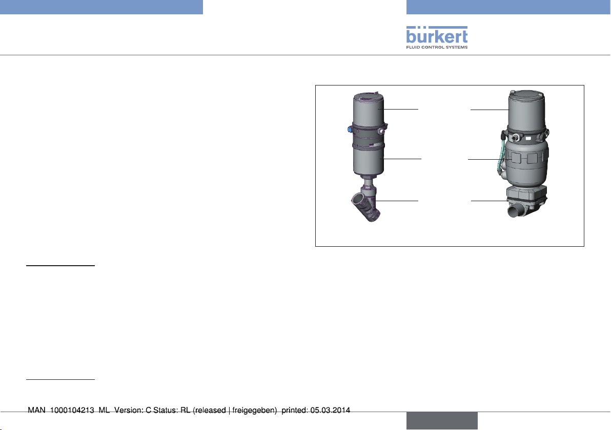
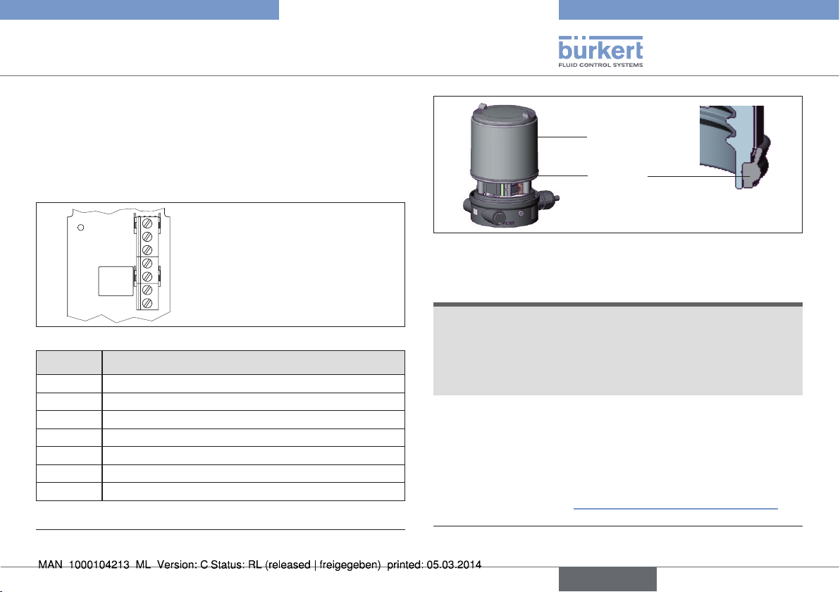
5. STRUCTURE AND FUNCTION
Positioner
Actuator
Valve body
Actuator + Valve body = Process valve
Fig. 1: Structure 1
Positioner Type 8694 is an electropneumatic position controller for
pneumatically actuated control valves with single-acting actuators.
Together with the pneumatic actuator, the positioner forms a functional
unit.
The control valve systems can be used for a wide range of control
tasks in fluid technology and, depending on the application conditions,
different process valves from the Bürkert range can be combined with
the positioner. Angle seat valves, straight seat valves, diaphragm valves
or ball valves are suitable.
The position of the actuator is regulated according to the position
set-point value. The nominal position value is specified by an external
standard signal.
english
7
Type 8694
Technical data
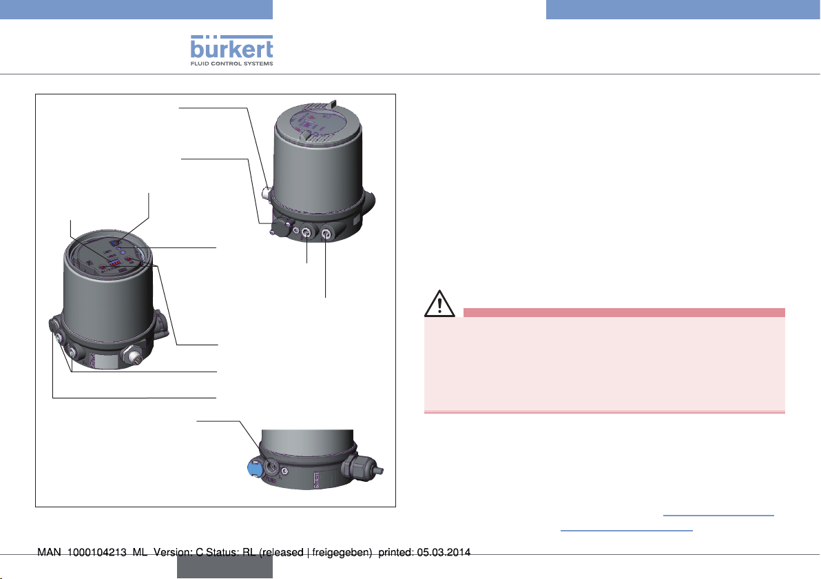
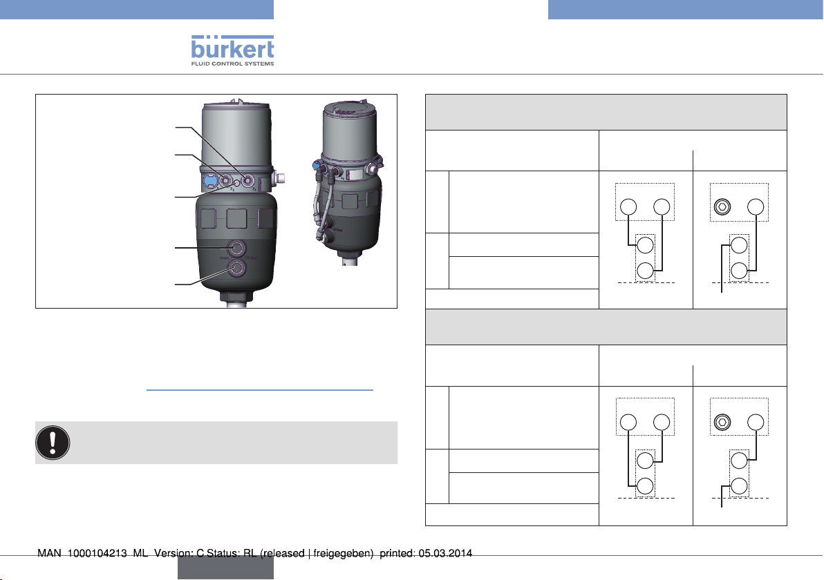
Electrical connection
(cable gland or circular
plug-in connector)
Pressure limiting valve
Communications interface
DIP Switches
Additional exhaust air port
(label: 3.1)
only for Type 23xx and 2103
with pilot-operated control
system for high air output
(actuator size ø 130)
Fig. 2: Structure 2
LED
Exhaust air port
(label: 3)
Pilot air port
(label: 1)
Keys
Pilot air outlet only for
series 26xx and 27xx
Air intake filter
6. TECHNICAL DATA
6.1. Conformity
In accordance with the EC Declaration of conformity, the positioner
Type 8694 is compliant with the EC Directives.
6.2. Standards
The applied standards, which verify conformity with the EC Directives, can be found on the EC-Type Examination Certificate and / or
the EC Declaration of Conformity.
6.3. Operating conditions
WARNING!
Solar radiation and temperature fluctuations may cause malfunctions or leaks.
• If the device is used outdoors, do not expose it unprotected to
the weather conditions.
• Ensure that the permitted ambient temperature does not exceed
the maximum value or drop below the minimum value.
Ambient temperature 0 – +60 °C
Protection class IP65 / IP67 according to EN 60529
(only if cables, plugs and sockets have
been connected correctly
and in compliance with the exhaust air
concept in chapter “8.3. Pneumatic connection of the positioner”).
8
english
Type 8694
Technical data
6.4. Mechanical data
Dimensions See data sheet
Body material exterior: PPS, PC, VA,
interior: PA 6; ABS
Sealing material EPDM / (NBR)
Stroke range
of valve spindle 2 – 45 mm
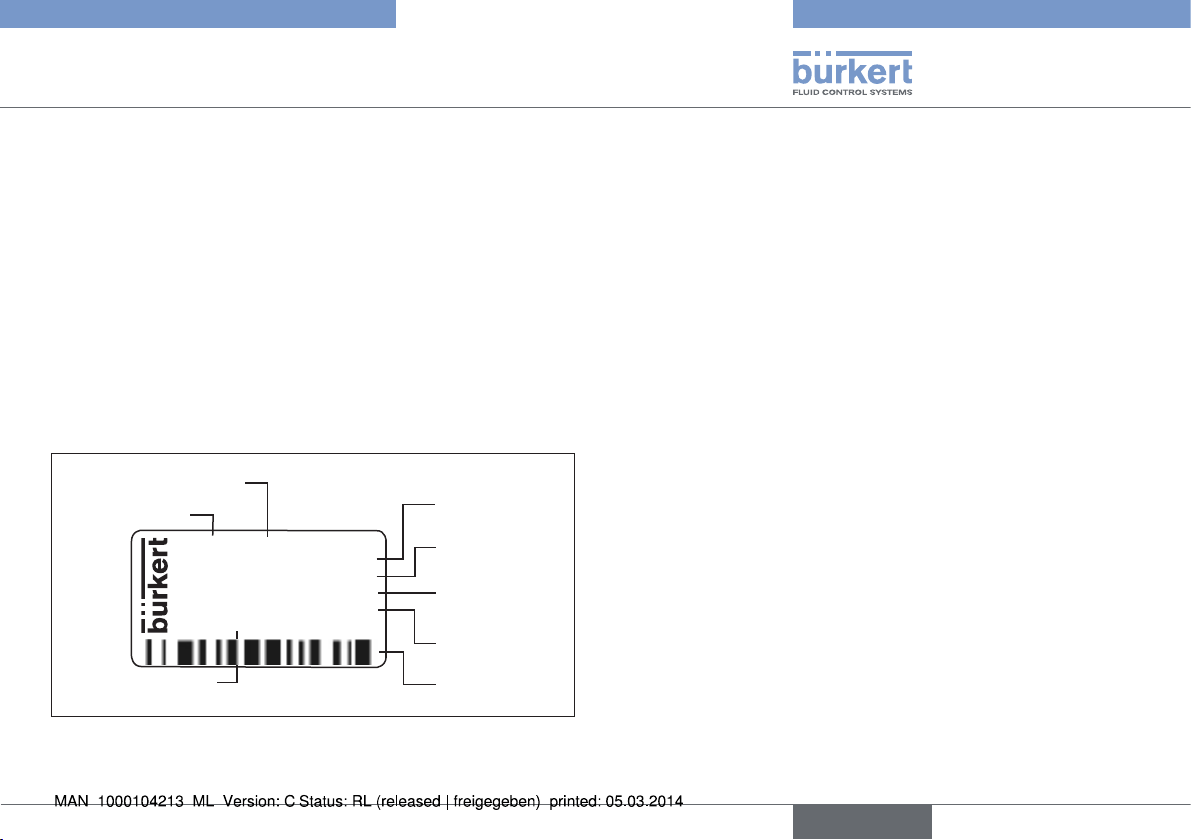
6.5. Type label
Example
Supply voltage / Control
Type
8694 24 V DC
single act Pilot 0,6
Pmax 7bar
D-74653 Ingelfingen
Identification number
Tamb 0°C - +60°C
S/N 001000
00185134
CE
W14UN
Control function
- Pilot valve
Nominal pressure
Max. ambient
temperature
Serial number CE mark
Bar-code
6.6. Pneumatic data
Control medium neutral gases, air
Quality classes in accordance with DIN ISO
8573-1
Dust content Class 5: max. particle size 40 µm,
max. particle density 10 mg/m³
Water content Class 3: max. pressure dew point
- 20 °C or min. 10 °C below the
lowest operating temperature
Oil content Class 5: max. 25 mg/m³
Temperature range
control medium 0 – +60 °C
Pressure range
control medium 3 – 7 bar
Air output of pilot valve 7 lN / min (for aeration and deaeration)
(Q
- value according to definition for
Nn
pressure drop from 7 to 6 bar absolute)
optional: 130 lN / min
(for aeration and deaeration)
(only single-acting)
Connections Plug-in hose connector ∅ 6 mm / 1/4“
Socket connection G 1/8
Fig. 3: Type label (example)
english
9
Type 8694
Technical data
6.7. Electrical data
6.7.1. Electrical data without bus control
24 V DC
Connections Cable gland M16 x 1.5, wrench size 22
(clamping area 5 – 10 mm)
with screw-type terminals for cable crosssections 0.14 – 1.5 mm²
Circular plug-in connector
(M12 x 1, 8-pole)
Pilot valve
Supply voltage 24 V DC ± 10 %
- max. residual ripple 10 %
Power input ≤ 3,5 W
Input resistance for
set-point value signal 75 Ω at 0/4 – 20 mA /
12 bit resolution
Protection class 3 in accordance with VDE 0580
Analogue position
feedback max. load
for current output
0/4 – 20 mA 560 Ω
Binary input 0 – 5 V = log “0”,
12 – 30 V = log “1”
inverted input in reverse order
Communications
interface Direct connection to PC via USB
adapter with integrated interface
driver, communication with communications software based on FDT/DTM
technology.
6.7.2. Electrical data with AS interface bus
control
Connections Circular plug-in connector
(M12 x 1, 4-pole)
Electrical supply voltage 29.5 V – 31.6 V DC
(according to specification)
Devices without external supply voltage:
Max. power consumption 150 mA
Devices with external supply voltage:
External supply voltage 24 V ± 10 %
The power supply unit must include a secure disconnection in
accordance with IEC 364-4-41(PELV or SELV)
Max. power consumption 100 mA
Max. power consumption
from AS interface 50 mA
10
english
Type 8694
Installation
6.8. Factory settings of the positioner
Functions can be activated via DIP switches:
Function Parameter Value
CUTOFF
CHARACT
DIR.CMD
Tab. 1: Factory settings - Functions
Additional functions are described in the operating instructions Type 8694 and in the communication software.
These instructions can be found on the Internet at
www.burkert.com.
1)
without change to the settings via the communications software a linear
characteristic is stored in FREE.
Sealing function below
Sealing function above
2 %
98 %
Select characteristic FREE
Effective direction set-point
rise
value
1)
7. INSTALLATION
Only for positioner without pre-assembled process valve.
7.1. Safety instructions
DANGER!
Risk of injury from high pressure!
• Before dismounting pneumatic lines and valves, turn off the
pressure and vent the lines.
Risk of electric shock!
• Before reaching into the device or the equipment, switch off the
power supply and secure to prevent reactivation!
• Observe applicable accident prevention and safety regulations
for electrical equipment!
WARNING!
Risk of injury from improper installation!
• Installation may be carried out by authorized technicians only
and with the appropriate tools!
Risk of injury from unintentional activation of the system and
an uncontrolled restart!
• Secure system from unintentional activation.
• Following assembly, ensure a controlled restart.
english
11
Type 8694
Installation
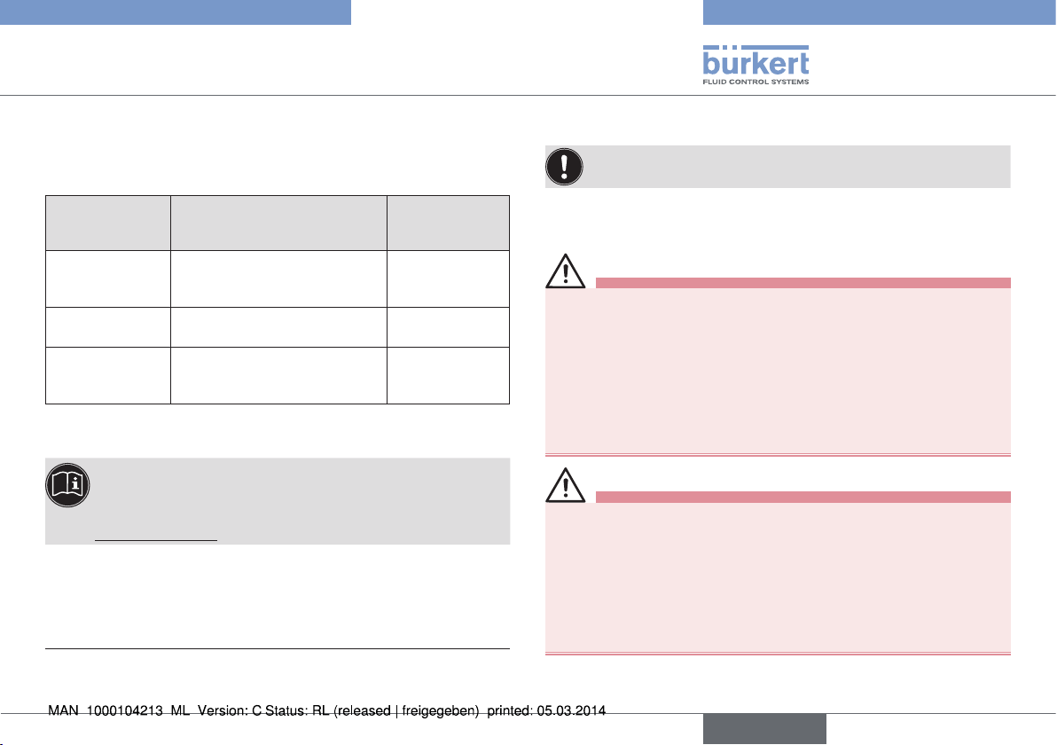
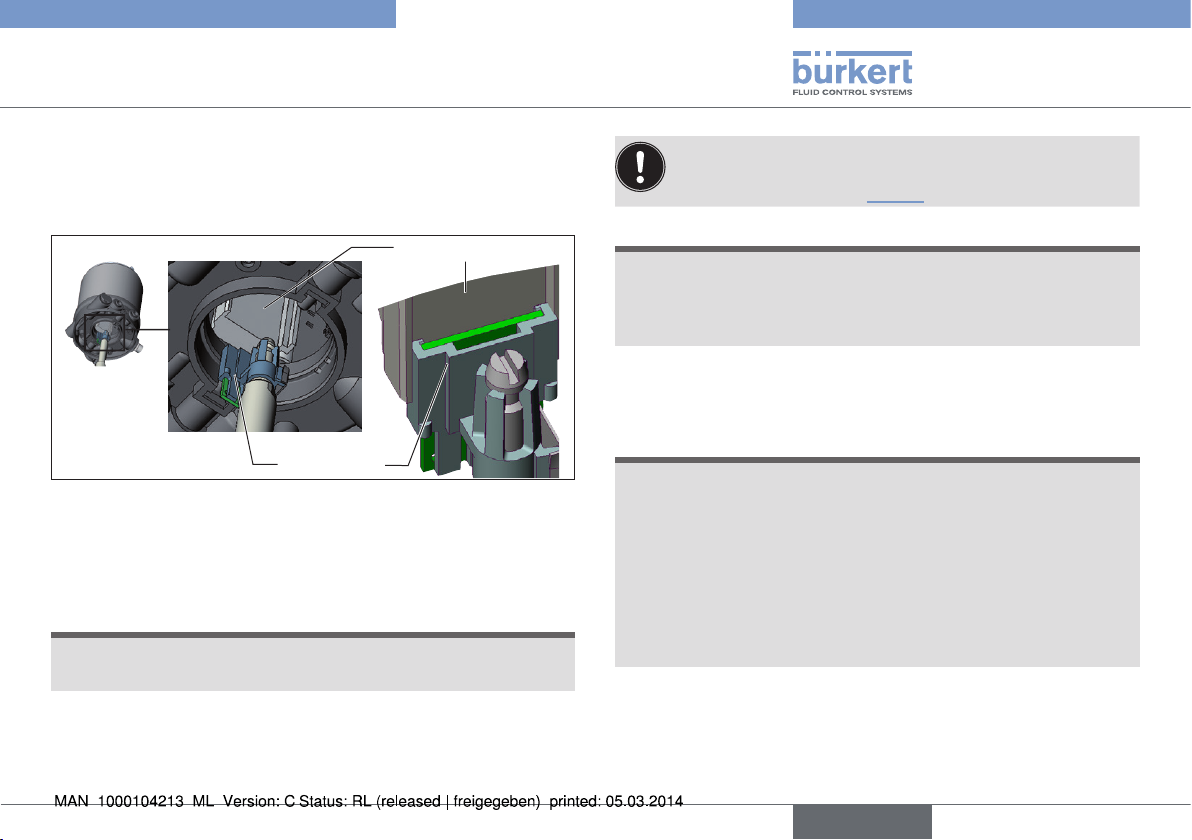
7.2. Installing the positioner on process
valves belonging to series 2103 and
23xx
Procedure:
When the positioner is being installed, the collets of the pilot
air ports must not be fitted to the actuator.
→ Align the puck holder and the positioner until
1. the puck holder can be inserted into the guide rail of the
positioner (see “Fig. 4”) and
2. the supports of the positioner can be inserted into the pilot
air ports of the actuator (see also “Fig. 5”).
NOTE!
Damaged printed circuit board or malfunction!
• Ensure that the puck holder is situated flat on the guide rail.
Guide rail
Puck holder
Fig. 4: Aligning the puck holder
→ Push the positioner, without turning it, onto the actuator until no
gap is visible on the form seal.
NOTE!
Too high torque when screwing in the fastening screw does
not ensure protection class IP65 / IP67!
• The fastening screws may be tightened to a maximum torque of
0.5 Nm only.
→ Attach the positioner to the actuator using the two side fastening
screws. In doing so, tighten the screws only hand-tight (max.
torque: 0.5 Nm).
Fastening
screws
Supports
Pilot air
ports
Actuator
Fig. 5: Aligning the puck holder, series 2103, 2300 and 2301
max. 0.5 Nm
12
english
Type 8694
Installation
7.3. Installing the positioner on process
valves belonging to series 26xx and
27xx
Procedure:
Guide rail
Puck holder
Fig. 6: Aligning the puck holder
→ Push the positioner onto the actuator. The puck holder must be
aligned in such a way that it is inserted into the guide rail of the
positioner.
NOTE!
Damaged printed circuit board or malfunction!
• Ensure that the puck holder is situated flat on the guide rail.
→ Press the positioner all the way down as far as the actuator and
turn it into the required position.
Ensure that the pneumatic connections of the positioner
and those of the actuator are situated preferably vertically
one above the other (see “Fig. 7”).
NOTE!
Too high torque when screwing in the fastening screw does
not ensure protection class IP65 / IP67!
• The fastening screws may be tightened to a maximum torque of
0.5 Nm only.
→ Attach the positioner to the actuator using the two side fastening
screws. In doing so, tighten the screws only hand-tight (max.
torque: 0.5 Nm).
NOTE!
Damage or malfunction due to ingress of dirt and moisture!
To observe protection class IP65 / IP67:
• In the case of actuator size ∅ 80, ∅ 100
connect the pilot air outlet which is not required to the free pilot
air port of the actuator or seal with a plug.
• In the case of actuator size ∅ 125
seal the pilot air outlet 2
feed the free pilot air port of the actuator via a hose into a dry
environment.
which is not required with a plug and
2
english
13
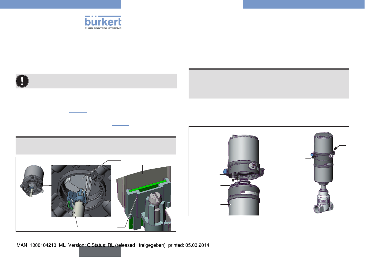
Pilot air outlet 2
Pilot air outlet 2
1
2
Fastening screws
max. 0.5 Nm
Upper pilot air port
Lower pilot air port
Fig. 7: Installing the pneumatic connection to actuator, series 26xx and
27xx
Example ∅ 80,
CFA
→ Make the pneumatic connection between the positioner and
actuator with the “Tab. 2: Pneumatic connection to actuator”.
Type 8694
Installation
Control function A (CFA)
Process valve closed in rest position (by spring force)
Actuator size ∅ 80, ∅ 100
Pilot air outlet
222
1
Positioner
Upper pilot air port
Lower pilot air port
Actuator
Dry area
Control function B (CFB)
Process valve open in rest position (by spring force)
Actuator size ∅ 80, ∅ 100
Pilot air outlet
222
1
∅ 125
222
∅ 125
222
1
1
“In rest position” means that the pilot valves of the positioner
Type 8694 are isolated or not actuated.
14
english
Positioner
Upper pilot air port
Lower pilot air port
Actuator
Dry area
Tab. 2: Pneumatic connection to actuator
Type 8694
Fluid installation
8. FLUID INSTALLATION
8.1. Safety instructions
DANGER!
Risk of injury from high pressure!
• Before dismounting pneumatic lines and valves, turn off the
pressure and vent the lines.
Risk of electric shock!
• Before reaching into the device or the equipment, switch off the
power supply and secure to prevent reactivation!
• Observe applicable accident prevention and safety regulations
for electrical equipment!
WARNING!
Risk of injury from improper installation!
• Installation may be carried out by authorized technicians only
and with the appropriate tools!
Risk of injury from unintentional activation of the system and
an uncontrolled restart!
• Secure system from unintentional activation.
• Following installation, ensure a controlled restart.
8.2. Installing the process valve
Thread type and dimensions can be found in the corresponding data
sheet.
→ Connect the valve according to the operating instructions for the
valve.
8.3. Pneumatic connection of the
positioner
DANGER!
Risk of injury from high pressure!
• Before dismounting pneumatic lines and valves, turn off the
pressure and vent the lines.
Procedure:
→ Connect the control medium to the pilot air port (1)
(3 – 7 bar; instrument air, free of oil, water and dust).
→ Attach the exhaust air line or a silencer to the exhaust air port (3)
and, if available to the exhaust air port (3.1) (see “Fig. 8”).
Keep the adjacent supply pressure always at least 0.5 – 1
bar above the pressure which is required to move the actuator
to its end position. This ensures that the control behavior is
not extremely negatively affected in the upper stroke range on
account of too little pressure difference.
During operation keep the fluctuations of the pressure supply
as low as possible (max. ±10 %). If fluctuations are greater,
the control parameters measured with the X.TUNE function
are not optimum.
english
15
Type 8694
Electrical installation
Important information for the problem-free functioning of
the device:
• The installation must not cause back pressure to build up.
• Select a hose for the connection with an adequate
cross-section.
• The exhaust air line must be designed in such a way that
no water or other liquid can get into the device through
the exhaust air port (3) or (3.1).
Exhaust air port
(label: 3)
Pilot air port
(label: 1)
Additional exhaust air port
(label: 3.1)
only for Type 23xx and 2103
with pilot-operated control system
for high air output (actuator size ø 130)
Fig. 8: Pneumatic Connection
Caution: (Exhaust air concept): In compliance with protection
class IP67, an exhaust air line must be installed in the dry area.
9. ELECTRICAL INSTALLATION
All electrical inputs and outputs of the device are not galvanically
isolated from the supply voltage.
9.1. Safety instructions
DANGER!
Risk of electric shock!
• Before reaching into the system, switch off the power supply
and secure to prevent reactivation!
• Observe applicable accident prevention and safety regulations
for electrical equipment!
WARNING!
Risk of injury from improper installation!
• Installation may be carried out by authorized technicians only
and with the appropriate tools!
Risk of injury from unintentional activation of the system and
an uncontrolled restart!
• Secure system from unintentional activation.
• Following installation, ensure a controlled restart.
9.2. Electrical installation 24 V DC
Two kinds of connections are used for the electrical bonding of the
positioner:
• Cable gland with screw-type terminals
• Multi-pole with circular plug-in connector M12 x 1, 8-pole
16
english
Type 8694
Electrical installation
9.2.1. Electrical installation with cable gland
Procedure:
→ The screw-type terminals can be accessed by unscrewing the
body casing (stainless steel).
→ Push the cables through the cable gland.
→ Connect the wires.
1
2)
2
2)
3
4
5
6
7
Fig. 9: Screw-type terminals
Terminal Configuration
1 Binary input +
2)
2
2)
3
4 Set-point value + (0/4 - 20 mA)
5 Set-point value GND
6 Supply voltage + 24 V DC
7 Supply voltage GND
Tab. 3: Electrical installation with cable gland
2) only optional
Analogue position feedback +
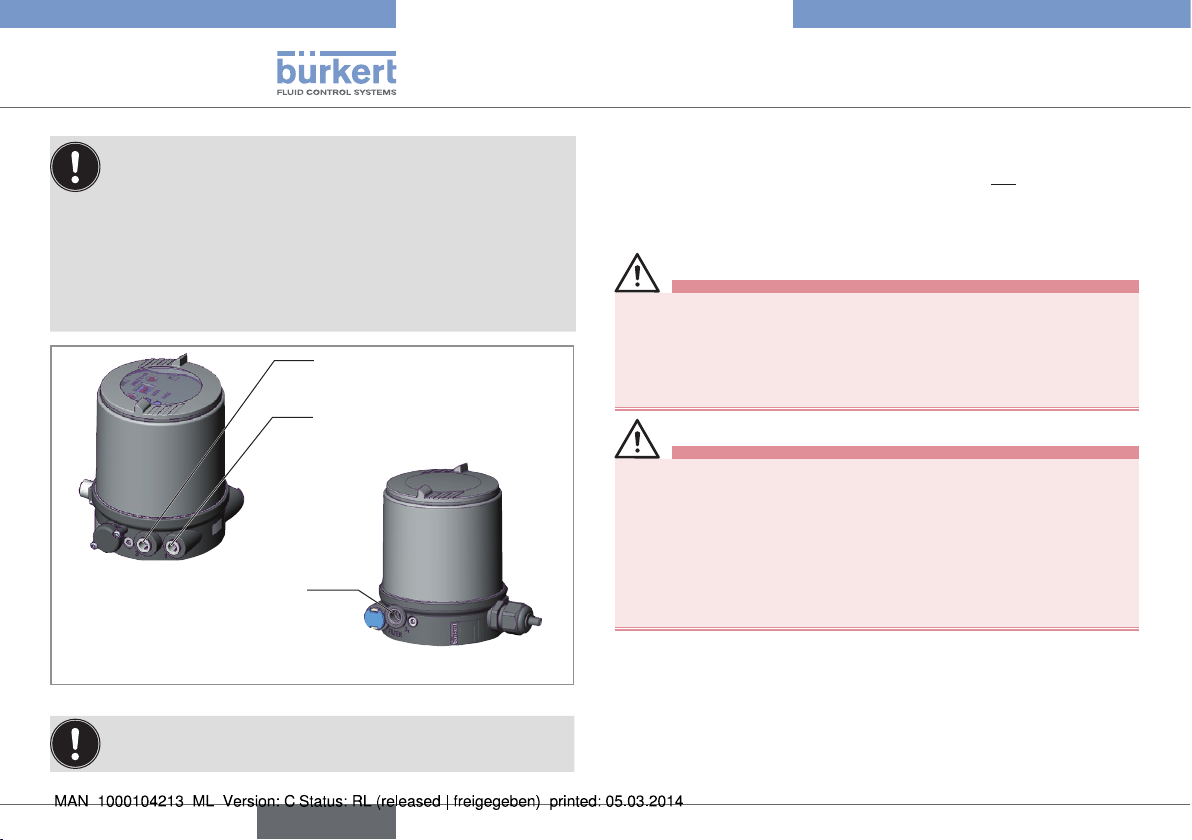
Analogue position feedback GND
Body casing
Seal
Body casing
Fig. 10: Position of the seal in the body casing
→ Check that the seal is correctly positioned in the body casing.
NOTE!
Damage or malfunction due to penetration of dirt and humidity!
To ensure protection class IP65 / IP67:
• Tighten the union nut on the cable gland according to the cable
size or dummy plugs used (approx. 1.5 Nm).
• Screw the body casing in all the way.
→ Tighten union nut on the cable gland (torque approx. 1.5 Nm).
→ Close the device (assembly tool: 674077
When the supply voltage is applied, the positioner is operating.
3)
).
→ Actuate the automatic adjustment of the positioner, as described
in the chapter entitled “10.2. Automatic adjustment X.TUNE”.
3) The assembly tool (674077) is available from your Bürkert sales office.
english
17
Type 8694
Electrical installation
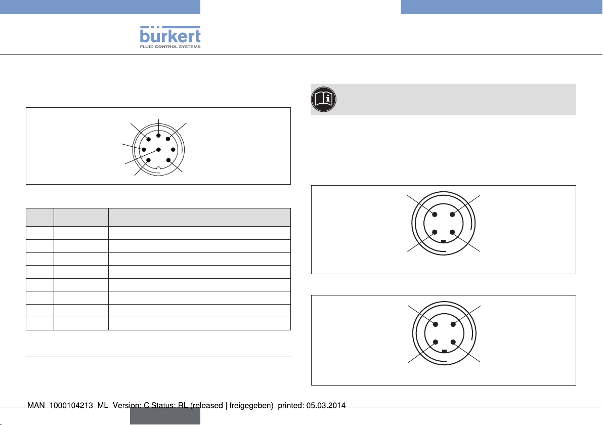
9.2.2. Electrical installation 24 V DC with
circular plug-in connector
→ Connect the positioner according to the table.
6
7
8
Fig. 11: Circular plug M12 x 1, 8-pole
Pin Wire color4)Designation
white
1
brown
2
green
3
yellow
4
grey
5
pink
6
Set-point value + (0/4 - 20 mA)
Set-point value GND
Supply voltage GND
Supply voltage + 24 V DC
Binary input +
Binary input GND
7 blau Analogue position feedback GND
8 rot Analogue position feedback +
Tab. 4: Connection with circular plug-in connector
4) The indicated colors refer to the connecting cable available as an
accessory (919061).
5) Only option.
5
4
3
1
2
5)
5)
9.3. Electrical installation AS Interface
A detailed description of the bus communication can be
found in the operating instructions Type 8694.
9.3.1. Connection with circular plug-in
connector M12 x 1, 4-pole, male
Connector views
The views show the image from the front looking at the pins, the
solder connections are behind them.
Pin 4:
NC
Pin 1:
Bus +
Fig. 12: Bus connection without external supply voltage
Pin 4:
24 V +
Pin 1:
Bus +
Fig. 13: Bus connection with external supply voltage (optional)
Pin 3:
Bus –
Pin 2:
NC
Pin 3:
Bus –
Pin 2:
GND
18
english
Type 8694
Start-up
Bus connection without external / with external supply voltage
Pin Designation Configuration
Bus + AS Interface bus line +
1
NC or GND
2
(optional)
Bus – AS Interface bus line –
3
NC or 24 V +
4
(optional)
Tab. 5: Pin assignment of circular plug-in connector for AS Interface
When the supply voltage is applied, the positioner is operating.
not used or external supply voltage –
(optional)
not used or external supply voltage +
(optional)
→ Actuate the automatic adjustment of the positioner, as described
in the chapter entitled “10.2. Automatic adjustment X.TUNE”.
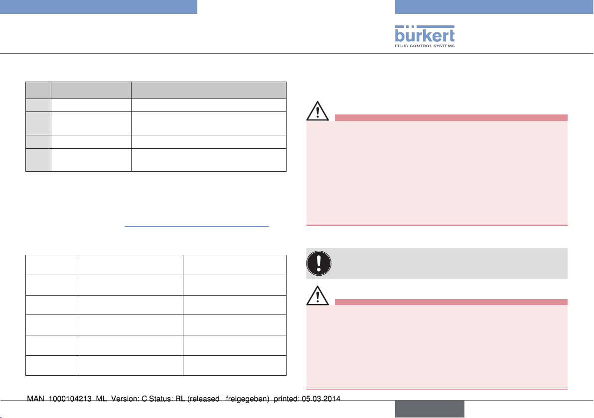
9.3.2. Programming data AS Interface
Version Profile S-7.3.4 Version Profile S-7.A.5
I/O configuration
ID code 3 hex (analog profile) A hex
Extended
ID code 1
Extended
ID code 2
Profile S-7.3.4 S-7.A.5
Tab. 6: Programming data
7 hex 7 hex
F hex (Default value, can
be changed by the user)
4 hex 5 hex
F hex
10. START-UP
10.1. Safety instructions
WARNING!
Risk of injury from improper operation!
Improper operation may result in injuries as well as damage to the
device and the area around it.
• Before start-up, ensure that the operating personnel are familiar
with and completely understand the contents of the operating
instructions.
• Observe the safety instructions and intended use.
• Only adequately trained personnel may operate the equipment/
the device.
10.2. Automatic adjustment X.TUNE
To adjust the positioner to local conditions, the X.TUNE
function must be run following installation.
WARNING!
Danger due to the valve position changing when the X.TUNE
function is running!
When the X.TUNE is running under operating pressure, there is an
acute risk of injury
• Never run X.TUNE while a process is running!
• Take appropriate measures to prevent the equipment from being
accidentally actuated!
english
19
Type 8694
Start-up
NOTE!
Avoid maladjustment of the controller due to an incorrect
pilot pressure or applied operating medium pressure!
• Run X.TUNE whenever the pilot pressure (= pneumatic auxiliary energy) is available during subsequent operation.
• Run the X.TUNE function preferably without operating medium
pressure to exclude interference caused by flow forces.
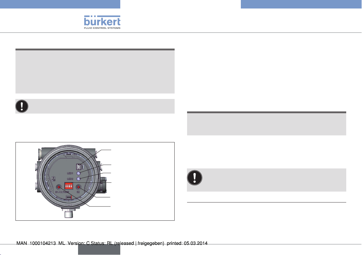
To run X.TUNE, the positioner must be in the AUTOMATIC
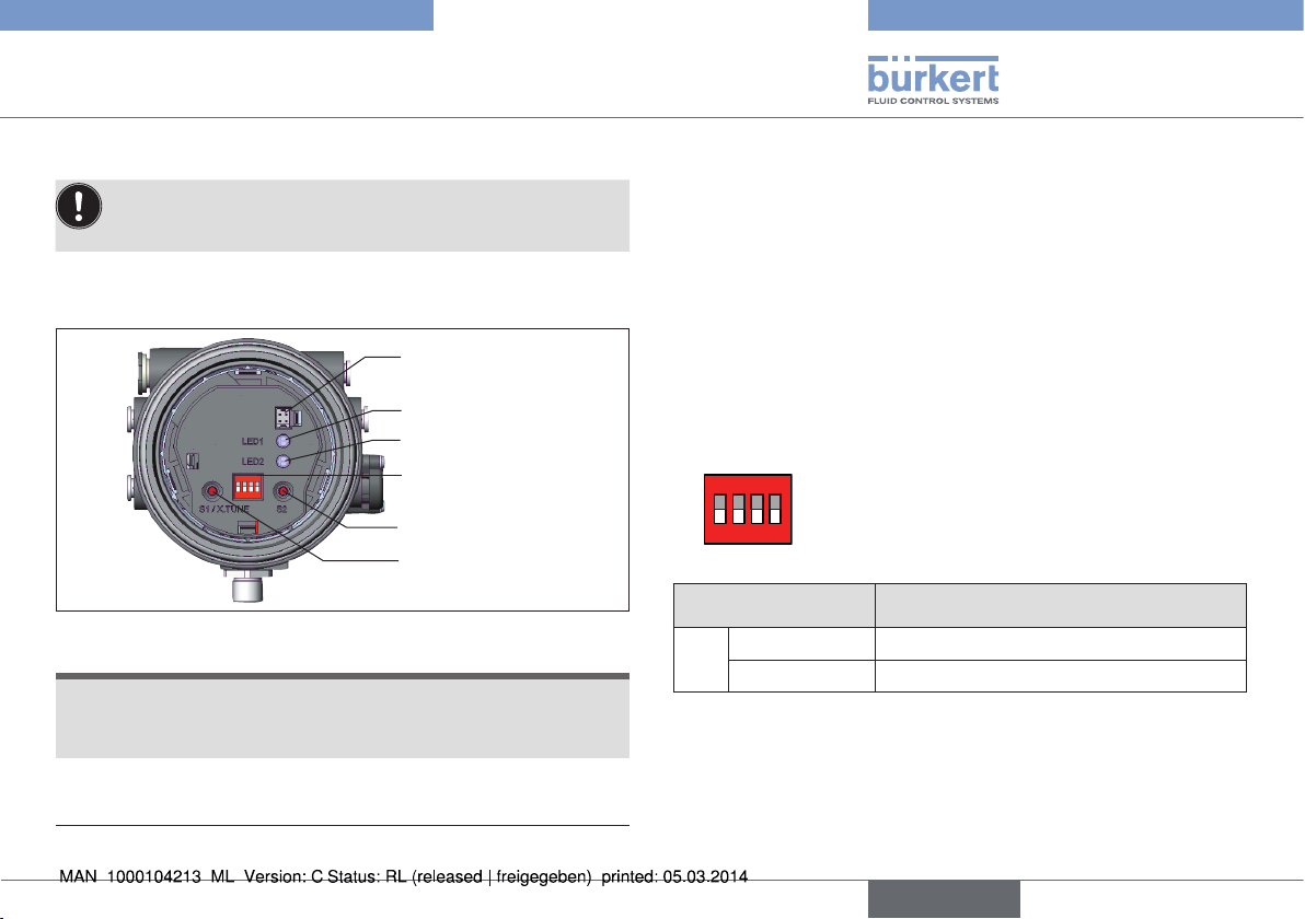
operating status (DIP switch 4 = OFF).
→ Screw off the transparent cap of the positioner to operate the
keys and DIP switches.
Communications
interface
LED 1
LED 2
ON DIP
1 2 3 4
Fig. 14: Automatic adjustment X.TUNE
DIP Switches
Key 2
Key 1
→ Start the X.TUNE by pressing key 1
6)
for 5 s.
While the X.TUNE is running, LED 1 flashes quickly (green).
When the automatic adjustment is complete, LED 1 flashes slowly
7)
(green)
.
The changes are automatically transferred to the memory (EEPROM)
provided the X.TUNE function is successful.
NOTE!
Damage or malfunction due to penetration of dirt and humidity!
• To observe protection class IP65 / IP67, screw the transparent
cap in all the way.
→ Close the device (assembly tool: 674077
8)
).
Important:
When the Teach function is activated the actuator cannot
be actuated via the AS Interface.
6) The X.TUNE can also be started via communications software.
7) If a fault occurs, LED 1 is lit red.
8) The assembly tool (674077) is available from your Bürkert sales office.
20
english
Type 8694
Start-up
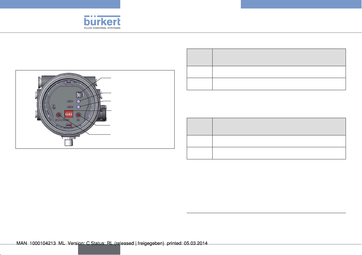
10.3. Control and display elements
A detailed description of the operation and functions of the
positioner and the communication software can be found in
the respective operating instructions.
→ Screw off the transparent cap of the positioner to operate the
keys and DIP switches.
Communications
interface
LED 1
LED 2
ON DIP
1 2 3 4
Fig. 15: Description of the control elements
NOTE!
Damage or malfunction due to penetration of dirt and humidity!
• To observe protection class IP65 / IP67, screw the transparent
cap in all the way.
→ Close the device (assembly tool: 674077
9) The assembly tool (674077) is available from your Bürkert sales office.
DIP Switches
Key 2
Key 1
9)
).
10.3.1. Operating status
AUTOMATIC (AUTO)
Normal controller mode is implemented and monitored in AUTO-
MATIC operating state.
LED 1 flashes green.
MANUAL (MANU)
In MANUAL operating state the valve can be opened and closed
manually via the keys.
LED 1 flashes red / green alternately.
ON DIP
The DIP switch 4 can be used to switch between
the two operating states AUTOMATIC and
2 3 4
1
MANUAL.
DIP switches Function
4 ON Operating status MANUAL (MANU)
OFF Operating status AUTOMATIC (AUTO)
Tab. 7: DIP switches
english
21
Type 8694
Start-up
10.3.2. Functions of the keys
The configuration of the 2 keys on the board varies depending on the
operating status (AUTOMATIC / MANUAL).
Communications
interface
LED 1
LED 2
ON DIP
1 2 3 4
DIP switches
Key 2
Key 1
Fig. 16: Keys
MANUAL operating status (DIP switch 4 set to ON):
Key Function
1 Aerate (manually open / close the actuator)
2 Deaerate (manually open / close the actuator)
Tab. 8: Configuration of the keys for MANUAL operating status
10)
11)
11)
AUTOMATIC operating status (DIP switch 4 set to OFF):
Key Function
1 Press for 5 s to start the X.TUNE function
2 -
Tab. 9: Configuration of the keys for AUTOMATIC operating status
10) No function if the binary input was activated with the “Manual/Auto
change-over” via the communications software.
11) depending on the operating principle of the actuator.
22
english
Type 8694
Start-up
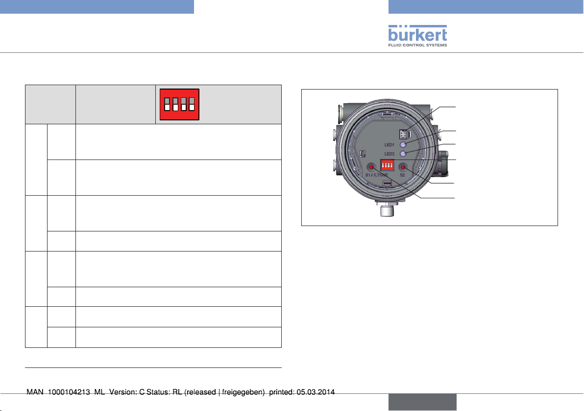
10.3.3. Function of the DIP switches
DIP
switches
Function
ON DIP
2 3 4
1
1 ON Reversal of the effective direction of the set-point
value (set-point value 20 – 4 mA corresponds to
position 0 – 100 %), descending (DIR.CMD)
OFF Normal effective direction of the set-point value
(set-point value 4 – 20 mA corresponds to position
0 – 100 %), ascending
2 ON Sealing function active. The valve completely closes
below 2 %
12)
and opens above 98 % of the set-point
value (CUTOFF)
OFF No sealing function
3 ON Correction characteristic for adjustment of the oper-
ating characteristic (linearization of the process characteristic CHARACT)
12)
OFF Linear characteristic
4 ON Operating status MANUAL (MANU)
OFF Operating status AUTOMATIC (AUTO)
10.3.4. Display of the LEDs
ON DIP
1 2 3 4
Fig. 17: Display of the LEDs
LED 1
(green / red)
LED 2
(green / yellow)
Display of
AUTO, MANU, X.TUNE and FAULT
Display of state of actuator
(open, closed, opens or closes)
Communications
interface
LED 1
LED 2
DIP switches
Key 2
Key 1
Tab. 10: DIP switches
12) Can be changed via communications software.
english
23
 Loading...