


VG4
AutoDome Modular Camera System
VG4 Series
en Installation Manual

AutoDome Modular Camera System | en iii
Preface
This manual describes how to install and mount the VG4 series AutoDome Modular Camera System. The manual
details the methods to mount the VG4 series to a wall, corner or mast; to a roof parapet or pipe; or in the ceiling.
The manual also includes information on cable and wire standards and information for connecting alarms and relays.
Audience
This manual is intended for qualified installation and service personnel who are familiar with the applicable national
and local electrical codes.
Document Conventions
Convention Meaning
Bold Denotes a part, item, or assembly.
Italic Denotes a reference to another paragraph, figure or table.
Underline
courier Denotes the actual name of an object, the exact code that should be typed or a message returned
Symbols
Used to emphasize a point.
from a system.
You may encounter these symbols within the document. Explanatory text accompanies each symbol, which provides
additional information detailing the operation or highlighting safety information.
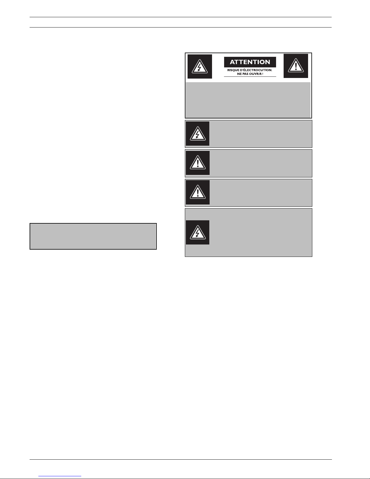
NOTICE! Notices inform you of essential but non-critical information. Read these messages
carefully as any directions or instructions contained therein can help you avoid making
i
mistakes.
CAUTION! Cautionary messages provide critical information that help you reduce the chance
of losing data or damaging the system. Please heed these messages.
WARNING! Warnings highlight information, that if overlooked may cause damage to the
system or result in personal injury. Take warnings seriously.
!
DANGER! Danger messages denote the presence of electrical equipment that may cause
electric shock or electrocution. Take care when you see this symbol to avoid serious injury or
death.
Bosch Security Systems, Inc. Installation Manual F01U010921 | 1.0 | 2006.10

iv en | AutoDome Modular Camera System
Customer Support and Service
If this unit needs service, contact the nearest Bosch Security Systems Service Center for authorization to return and
shipping instructions.
Service Centers
USA
Phone: 800-366-2283 or 585-340-4162
Fax: 800-366-1329
Email: cctv.repair@us.bosch.com
Technical Support
Phone: 800-326-1450
Email: technical.support@us.bosch.com
CCTV Spare Parts
Phone: 800-894-5215 or 408-957-3065
Fax: 408-935-5938
Email: BoschCCTVparts@ca.slr.com
Canada
Phone: 514-738-2434
Fax: 514-738-8480
Europe, Middle East & Asia Pacific Region
Phone: 44 (0) 1495 274558
Fax: 44 (0) 1495 274280
Email: rmahelpdesk@solectron.com
For additional information, see www.boschsecurity.com
Related Publications
Refer to the latest Bosch Security Systems, Inc. Databook for the most up-to-date datasheets. To obtain a copy of
the Databook, please contact your local Bosch representative.
You can also visit the Bosch Security Systems World Wide Web site at: http://www.boschsecurity.com to view a current listings of our publications.
F01U010921 | 1.0 | 2006.10 Installation Manual Bosch Security Systems, Inc.

AutoDome Modular Camera System Table of Contents | en v
Table of Contents
Preface iii Important Safeguards vii
1 Installing the Pendant Arm Wall, Corner, and Mast (Pole) Mounts ......................................................... 3
1.1 Unpacking.................................................................................................................................................... 3
1.2 Pre-installation Checklist............................................................................................................................. 5
1.3 Mount Power Supply Box ............................................................................................................................ 6
1.4 Route Wires and Attach Connectors............................................................................................................ 7
1.5 Attach Pendant Arm to Power Supply Box ................................................................................................ 10
1.6 Make Connections in Power Supply Box ................................................................................................... 11
1.7 Assemble Pendant in Packing Box............................................................................................................. 13
1.8 Attach Pendant to Arm and Tighten........................................................................................................... 15
2 Installing Roof Parapet and Pipe Mounts ................................................................................................ 17
2.1 Unpacking.................................................................................................................................................. 17
2.2 Pre-installation Check List......................................................................................................................... 19
2.3 Mount Power Supply Box .......................................................................................................................... 20
2.4 Route Wires and Attach Connectors.......................................................................................................... 22
2.5 Installing the VG4-A-9230 Roof Parapet Mount ......................................................................................... 26
2.6 Installing the VG4-A-9543 Pipe Mount ....................................................................................................... 30
2.7 Wire Pipe Interface Board.......................................................................................................................... 31
2.8 Assemble the Pendant in Packing Box....................................................................................................... 34
2.9 Attach Pendant to Pipe and Tighten.......................................................................................................... 36
2.10 Make Connections in Power Supply Box ................................................................................................... 37
3 Installing the In-Ceiling Mount ................................................................................................................. 39
3.1 Unpacking.................................................................................................................................................. 39
3.2 Pre-installation Check List......................................................................................................................... 41
3.3 Dimensions ................................................................................................................................................ 41
3.4 Prepare Drywall Ceiling for Installation ..................................................................................................... 42
3.5 Prepare Suspension Ceiling for Installation .............................................................................................. 42
3.6 Wire the Interface Box ............................................................................................................................... 44
3.7 Attach Housing to the Interface Box.......................................................................................................... 46
3.8 Secure Housing to Ceiling ......................................................................................................................... 47
3.9 Align and Install Camera Module ............................................................................................................... 48
3.10 Attach Bubble ............................................................................................................................................ 49
4 Cable and Wire Standards........................................................................................................................ 51
4.1 Power ........................................................................................................................................................ 51
4.2 Wire Distance Guide for Pendant .............................................................................................................. 51
4.3 Video and Control Cables .......................................................................................................................... 52
4.4 Control-only Cables ................................................................................................................................... 54
5 Alarms and Relay Connections................................................................................................................. 57
5.1 Alarm Inputs .............................................................................................................................................. 57
5.2 Configuring Supervised Alarms (inputs 1 and 2)....................................................................................... 57
5.3 Configuring Non-supervised Alarms (inputs 1 through 7) ......................................................................... 58
Bosch Security Systems, Inc. Installation Manual F01U010921 | 1.0 | 2006.10

vi en | Table of Contents AutoDome Modular Camera System
5.4 Alarm Outputs............................................................................................................................................ 59
6 Glossary .................................................................................................................................................... 61
7 Index ......................................................................................................................................................... 71
F01U010921 | 1.0 | 2006.10 Installation Manual Bosch Security Systems, Inc.

Important Safeguards
1. Read, Follow, and Retain Instructions - All safety and operating
instructions should be read and followed before operating the unit.
Retain instructions for future reference.
2. Heed Warnings - Adhere to all warnings on the unit and in the operating instructions.
3. Attachments - Attachments not recommended by the product manufacturer should not be used, as they may cause hazards.
4. Installation Cautions - Do not place this unit on an unstable stand,
tripod, bracket, or mount. The unit may fall, causing serious injury to
a person and serious damage to the unit. Use only manufacturer-recommended accessories, or those sold with the product. Mount the
unit per the manufacturer's instructions. Appliance and cart combination should be moved with care. Quick stops, excessive force, or
uneven surfaces may cause the appliance and cart combination to
overturn.
5. Cleaning - Unplug the unit from the outlet before cleaning. Follow any
instructions provided with the unit. Generally, using a damp cloth for
cleaning is sufficient. Do not use liquid cleaners or aerosol cleaners.
6. Servicing - Do not attempt to service this unit yourself. Opening or
removing covers may expose you to dangerous voltage or other hazards. Refer all servicing to qualified service personnel.
7. Damage Requiring Service - Unplug the unit from the main AC power
source and refer servicing to qualified service personnel under the
following conditions:
• When the power supply cord or plug is damaged.
• If liquid has been spilled or an object has fallen into the unit.
• If the unit has been exposed to water and/or inclement weather
(rain, snow, etc.).
• If the unit does not operate normally, when following the operat-
ing instructions. Adjust only those controls specified in the operating instructions. Improper adjustment of other controls may
result in damage, and require extensive work by a qualified technician to restore the unit to normal operation.
• If the unit has been dropped or the cabinet damaged.
• If the unit exhibits a distinct change in performance, this indicates
that service is needed.
8. Replacement Parts - When replacement parts are required, the service technician should use replacement parts specified by the manufacturer or that have the same characteristics as the original part.
Unauthorized substitutions may result in fire, electrical shock or
other hazards.
9. Safety Check - Upon completion of servicing or repairs to the unit,
ask the service technician to perform safety checks to ensure proper
operating condition.
| en vii
10.Power Sources - Operate the unit only from the type of power source
indicated on the label. If unsure of the type of power supply to use,
contact your dealer or local power company.
• For units intended to operate from battery power, refer to the
operating instructions.
• For units intended to operate with External Power Supplies, use
only the recommended approved power supplies.
• For units intended to operate with a limited power source, this
power source must comply with EN60950. Substitutions may
damage the unit or cause fire or shock.
• For units intended to operate at 24VAC, normal input voltage is
24VAC. Voltage applied to the unit's power input should not
exceed 30VAC.
User-supplied wiring, from the 24VAC supply to unit, must be in compliance with electrical codes (Class 2 power levels). Do not ground
the 24VAC supply at the terminals or at the unit's power supply terminals.
11.Coax Grounding - If an outside cable system is connected to the unit,
ensure that the cable system is grounded. U.S.A. models only - Section 810 of the National Electrical Code, ANSI/NFPA No.70, provides
information regarding proper grounding of the mount and supporting
structure, grounding of the coax to a discharge unit, size of grounding
conductors, location of discharge unit, connection to grounding electrodes, and requirements for the grounding electrode.
12.Grounding - This unit may be equipped with a 3-wire grounding plug
(a plug with a third pin, for grounding). This safety feature allows the
plug to fit into a grounding power outlet only. If unable to insert the
plug into the outlet, contact an electrician to arrange replacement of
the obsolete outlet. Do not defeat the safety purpose of the grounding plug.
• Outdoor equipment should only be connected to the unit's inputs
after this unit has had its grounding plug connected to a grounded
outlet or its ground terminal properly connected to a ground
source.
• The unit's input connectors must be disconnected from outdoor
equipment before disconnecting the grounding plug or grounding
terminal.
• Proper safety precautions such as grounding should be followed
for any outdoor device connected to this unit.
13.Lightning - For added protection during a lightning storm, or when
this unit is left unattended and unused for long periods of time,
unplug the unit from the wall outlet and disconnect the cable system.
This will prevent damage to the unit due to lightning and power line
surges.
Bosch Security Systems, Inc.
viii en |
For Indoor Product
1. Water and Moisture - Do not use this unit near water for example, in a wet basement, in an unprotected outdoor installation or in any area classified as a wet location.
2. Object and Liquid Entry - Never push objects of any
kind into this unit through openings, as they might touch
dangerous voltage points or create short circuits, resulting in a fire or electrical shock. Never spill liquid of any
kind on the unit.
3. Power Cord and Power Cord Protection - For units
intended to operate with 230VAC, 50Hz, the input and
output power cord must comply with the latest versions
of IEC Publication 227 or IEC Publication 245. Power
supply cords should be routed so they are not likely to
be walked on or pinched. Pay particular attention to
location of cords and plugs, convenience receptacles,
and the point of exit from the appliance.
4. Overloading - Do not overload outlets and extension
cords; this can result in a risk of fire or electrical shock.
For Outdoor Product
Power Lines - An outdoor system should not be located
in the vicinity of overhead power lines, electric lights or
power circuits, or where it may contact such power lines
or circuits. When installing an outdoor system, extreme
care should be taken to keep from touching power lines
or circuits, as this contact might be fatal. U.S.A. models
only - refer to the National Electrical Code Article 820
regarding installation of CATV systems.
For Rack-mount Product
1. Ventilation - Do not place this equipment in a built-in
installation or rack, unless proper ventilation is provided, or the manufacturer's instructions were followed.
The equipment must not exceed its maximum operating
temperature requirements.
2. Mechanical Loading - When rack-mounting the equipment, ensure that a hazardous condition is not created
by uneven mechanical loading.
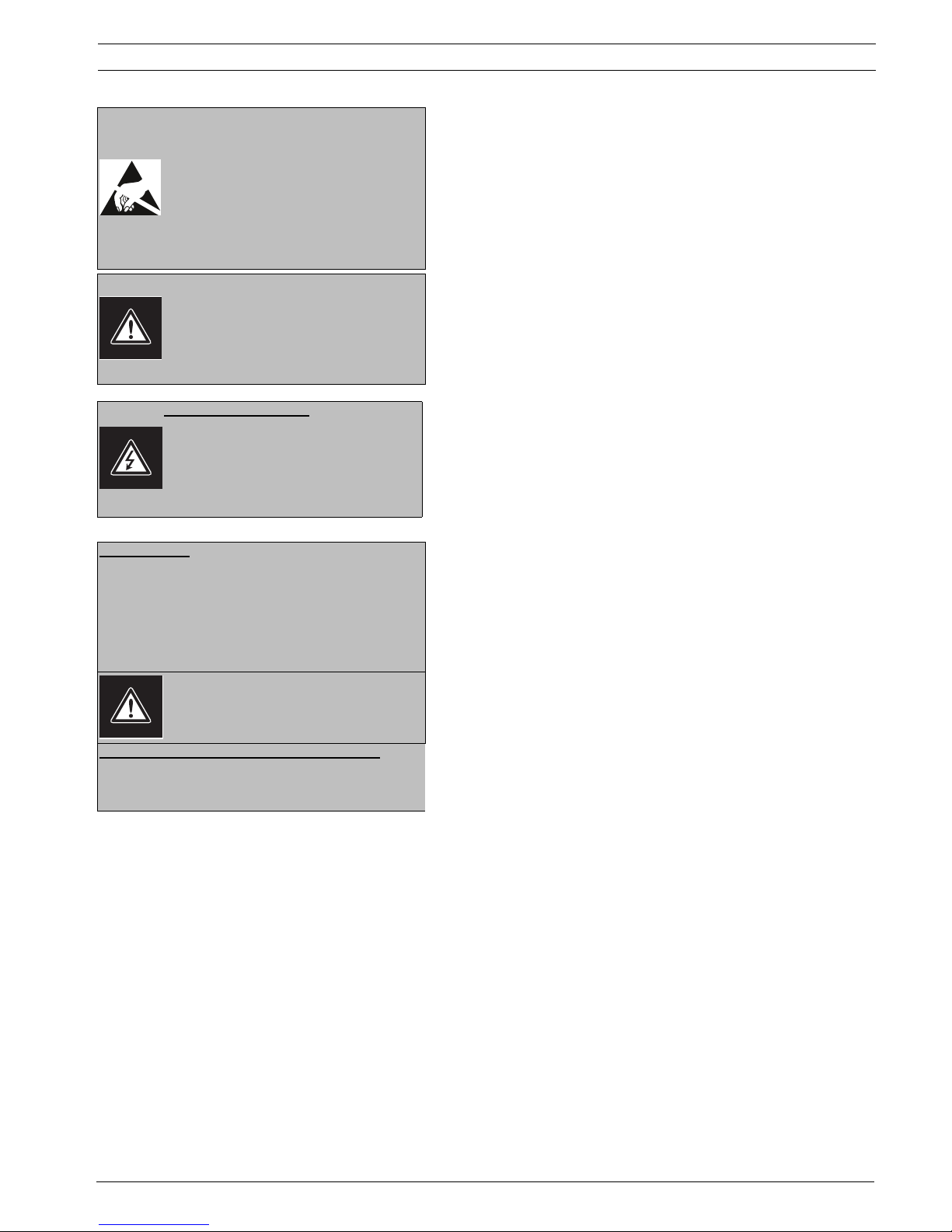
WARNING:
Electrostatic-sensitive device. Use proper CMOS/
MOSFET handling precautions to avoid electrostatic discharge.
NOTE: Grounded wrist straps must be worn and
proper ESD safety precautions observed when
handling the electrostatic-sensitive printed circuit
boards.
This symbol indicates the presence of important
operating and maintenance (servicing) instructions in the literature accompanying the appliance.
Cover Removal
Warning: Removal of the cover should only be
performed by qualified service personnel - not
user serviceable. The unit should always be
unplugged before removing the cover and remain
unplugged while the cover is removed.
24 VAC Units
Do not exceed 30VAC input. Voltage applied to the unit's
power input should not exceed 30VAC. Normal input voltage is
24VAC. User supplied wiring from 24VAC supply to unit must
be in compliance with electrical codes (Class 2 power levels).
Do not ground 24VAC supply at power supply terminals or at
unit's power supply terminals.
This equipment is to be isolated from the mains
supply by a limited power source as specified in
EN60950.
220-240V, 50Hz Power Cords
220-240V, 50Hz power cords, input and output, must comply
with the latest versions of IEC Publication 227 or IEC Publication 245.
Bosch Security Systems, Inc.
| en ix
FCC & ICES INFORMATION
(U.S.A. and Canadian Models Only)
This device complies with part 15 of the FCC Rules. Operation is subject
to the following two conditions:
(1)This device may not cause harmful interference, and
(2)This device must accept any interference received, including inter-
ference that may cause undesired operation.
NOTE: This equipment has been tested and found to comply with the
limits for a Class A digital device, pursuant to Part 15 of the FCC Rules
and ICES-003 of Industry Canada. These limits are designed to provide
reasonable protection against harmful interference when the equipment
is operated in a commercial environment. This equipment generates,
uses and radiates radio frequency energy, and if not installed and used
in accordance with the instruction manual, may cause harmful interference to radio communications. Operation of this equipment in a residential area is likely to cause harmful interference, in which case the user
will be required to correct the interference at his expense.
Intentional or unintentional changes or modifications, not expressly
approved by the party responsible for compliance, shall not be made.
Any such changes or modifications could void the user’s authority to
operate the equipment. If necessary, the user should consult the dealer
or an experienced radio/television technician for corrective action. The
user may find the following booklet, prepared by the Federal Communications Commission, helpful: How to Identify and Resolve Radio-TV Inter-
ference Problems. This booklet is available from the U.S. Government
Printing Office, Washington, DC 20402, Stock No. 004-000-00345-4.
WARNING: This is a Class A product. In a domestic environment, this product may cause radio interference, in which
case, the user may be required to take adequate measures.
Safety Precautions
CAUTION: TO REDUCE THE RISK OF ELECTRIC SHOCK, DO
NOT REMOVE COVER (OR BACK). NO USER SERVICEABLE
PARTS INSIDE. REFER SERVICING TO QUALIFIED SERVICE
PERSONNEL.
This symbol indicates the presence of uninsulated
“dangerous voltage” within the product’s enclosure that can cause an electric shock.
This symbol indicates the presence of important
operating and maintenance (servicing) instructions in the literature accompanying the appliance.
Installation should be performed by qualified service personnel only in accordance with the
National Electrical Code or applicable local codes.
Power Disconnect. Units with or without ON-OFF
switches have power supplied to the unit whenever the power cord is inserted into the power
source; however, the unit is operational only when
the ON-OFF switch is in the ON position. The
power cord is the main power disconnect for all
units.
Bosch Security Systems, Inc.
x en |
INFORMATIONS FCC ET ICES
(modèles utilisés aux États-Unis et au Canada uniquement)
Ce produit est conforme aux normes FCC partie 15. la mise en service
est soumises aux deux conditions suivantes:
(1) cet appareil ne peut pas provoquer d'interférence nuisible et
(2) cet appareil doit pouvoir tolérer toutes les interférences auxquelles
il est soumit, y compris les interférences qui pourraient influer sur
son bon fonctionnement.
AVERTISSEMENT: Suite à différents tests, cet appareil s’est révélé conforme aux exigences imposées aux appareils numériques de Classe A en
vertu de la section 15 du règlement de la Commission fédérale des communications des États-Unis (FCC). Ces contraintes sont destinées à
fournir une protection raisonnable contre les interférences nuisibles
quand l'appareil est utilisé dans une installation commerciale. Cette
appareil génère, utilise et émet de l'energie de fréquence radio, et peut,
en cas d'installation ou d'utilisation non conforme aux instructions,
générer des interférences nuisibles aux communications radio. L’utilisation de ce produit dans une zone résidentielle peut provoquer des interférences nuisibles. Le cas échéant, l’utilisateur devra remédier à ces
interférences à ses propres frais.
Au besoin, l’utilisateur consultera son revendeur ou un technicien qualifié en radio/télévision, qui procédera à une opération corrective. La brochure suivante, publiée par la Commission fédérale des communications
(FCC), peut s’avérer utile : « How to Identify and Resolve Radio-TV Interference Problems » (Comment identifier et résoudre les problèmes
d’interférences de radio et de télévision). Cette brochure est disponible
auprès du U.S. Government Printing Office, Washington, DC 20402,
États-Unis, sous la référence n° 004-000-00345-4.
Avertissement : Ce produit est un appareil de Classe A. Son
utilisation dans une zone résidentielle risque de provoquer
des interférences. Le cas échéant, l’utilisateur devra prendre
les mesures nécessaires pour y remédier.
Sécurité
Attention: l'installation doit exclusivement être réalisée par du
ATTENTION : POUR ÉVITER TOUT RISQUE D'ÉLECTROCUTION, N'ESSAYEZ PAS DE RETIRER LE CAPOT (OU LE PANNEAU ARRIÈRE). CET APPAREIL NE CONTIENT AUCUN
COMPOSANT SUSCEPTIBLE D'ÊTRE RÉPARÉ PAR L'UTILISATEUR. CONFIEZ LA RÉPARATION DE L'APPAREIL À DU
PERSONNEL QUALIFIÉ.
Ce symbole signale que le produit renferme une «
tension potentiellement dangereuse » non isolée
susceptible de provoquer une électrocution.
Ce symbole invite l'utilisateur à consulter les
instructions d'utilisation et d'entretien (dépannage) reprises dans la documentation qui
accompagne l'appareil.
Attention: l'installation doit exclusivement être
réalisée par du personnel qualifié, conformément
au code national d'électricité américain (NEC) ou
au code d'électricité local en vigueur.
Coupure de l'alimentation. Qu'ils soient pourvus
ou non d'un commutateur ON/OFF, tous les appareils reçoivent de l'énergie une fois le cordon
branché sur la source d'alimentation. Toutefois,
l'appareil ne fonctionne réellement que lorsque le
commutateur est réglé sur ON. Le débranchement
du cordon d'alimentation permet de couper l'alimentation des appareils.
Bosch Security Systems, Inc.
AVERTISSEMENT:
cet appareil est sensible aux décharges électrostatiques. Pour éviter tout risque de décharge électrostatique, observez les précautions de
manipulation du CMOS/MOSFET appropriées.
REMARQUE: lors de la manipulation des cartes à
circuits imprimés sensibles aux décharges électrostatiques, portez des bracelets antistatiques
mis à la terre et observez les consignes de sécurité relatives aux décharges électrostatiques.
ATTENTION: pile au lithium
Le remplacement incorrect de la pile risque de
provoquer une explosion. Remplacez la pile exclusivement par une pile identique ou par un type de
pile équivalent recommandé par le fabricant.
Débarrassez-vous de la pile usagée conformément
aux instructions de son fabricant.
Enlèvement du capot
Avertissement: L’enlèvement du capot ne doit
être effectué que par un technicien spécialisé. Il
n’y a pas de pièces remplaçables ou réglables par
l’utilisateur. Il faut toujours débrancher l’appareil
avant d’enlever le capot et le laisser débranché
jusqu’à la remise en place du capot.
| en xi
24 VAC Units
Ne pas excéder 30 V c.a. La tension appliquée à l’entrée d’alimentation de l’appareil ne doit pas excéder 30 V c.a. La valeur
normale de la tension d’entrée est 24 V c.a. Le circuit électrique reliant l’alimentation 24 V c.a. à l’appareil doit être conforme aux codes électriques (niveaux d’alimentation de classe
2). Ne pas mettre l’alimentation 24 V c.a. à la masse au niveau
des bornes de l’alimentation ou de l’appareil.
Cet équipement doit être isolé de l’alimentation
secteur par une source de puissance limitée, conformément à la norme EN60950.
Cordons d’alimentation 220-240 V, 50 Hz
Les cordons d’alimentation 220-240 V, 50 Hz, d’entrée ou de
sortie, doivent être conformes à la dernière version de la publication IEC 227 ou IEC 245.
Bosch Security Systems, Inc.

xii en |
Bosch Security Systems, Inc.

AutoDome Modular Camera System Installing the Pendant Arm Wall, Corner, and Mast (Pole) Mounts | en 3
1 Installing the Pendant Arm Wall, Corner, and Mast
(Pole) Mounts
1.1 Unpacking
This equipment should be unpacked and handled with care. If an item appears to have been
damaged in shipment, notify the shipper immediately.
Verify that all the parts listed in the Parts List below are included. If any items are missing,
notify your Bosch Security Systems Sales or Customer Service Representative. See Customer
Support and Service on page iv.
The original packing carton is the safest container in which to transport the unit and must be
used if returning the unit for service. Save it for possible future use.
1.1.1 Parts List
The following table lists the parts included with the Pendant Arm Wall, Corner, or Mast mount
packages.
Mount Kit Options Part Numbers
Pendant Arm (Only) F01U010586
Pendant Housing (with COMMS and CPU modules installed) VG4-XXX
Pendant Arm with one of the following Power Supply Boxes
– Power Box without transformer (24 VAC) VG4-A-PA0
– Power Box with 120 VAC transformer
or with 230 VAC transformer
– Power Box without transformer with Fiber Optic Module (24 VAC) VG4-A-PA0F
– Power Box with 120 VAC transformer and Fiber Optic Module
or with 230 VAC transformer and Fiber Optic Module
Trim Skirt Power Supply Box F01U005225
Corner Mount Kit
– Corner Mount Plate LTC 9542/01
Mast (Pole) Mount Kit
– Mast Mount Plate LTC 9541/01
VG4-A-PA1
VGA-A-PA2
VG4-A-PA1F
VG4-A-PA2F
Bosch Security Systems, Inc. Installation Manual F01U010921 | 1.0 | 2006.10
4 en | Installing the Pendant Arm Wall, Corner, and Mast (Pole) Mounts AutoDome Modular Camera System
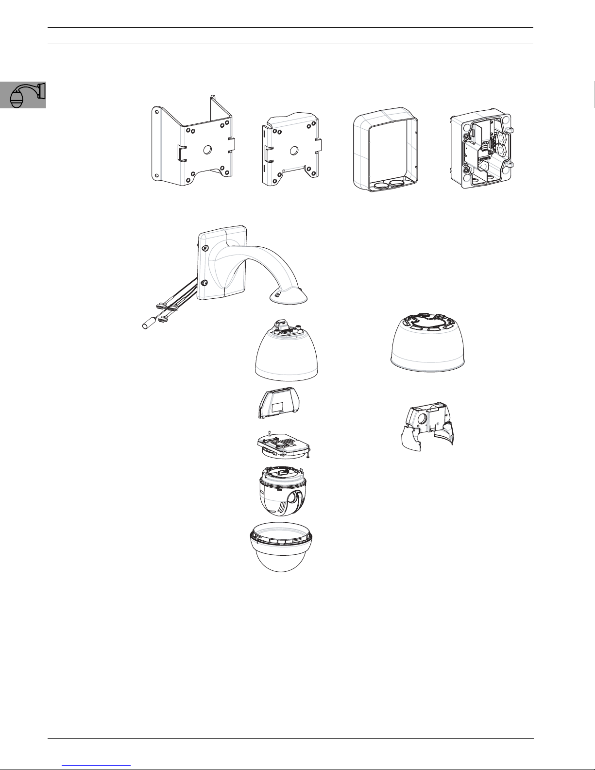
The following figures depict the parts (some optional) pendant arm wall, corner, or mast
mount.
Corner Plate
CORNER PLATE
(Optional)
(OPTIONAL)
Pendant Arm
PENDANT ARM
PENDANT HOUSING
COMMS MODULE
Pendant Housing
COMMS Module
CPU MODULE
CPU Module
Mast Plate
MAST PLATE
(Optional)
(OPTIONAL)
Trim Skirt
TRIM SKIRT
ENVIROMENTAL SHIELD
Environmental Shield
(OPTIONAL)
HEATER MODULE
Heater Module
(OPTIONAL)
(Optional)
(Optional)
Power Supply
POWER SUPPLY
CAMERA MODULE
DOME BUBBLE
Fig. 1.1 Pendant Arm Parts
1.1.2 Description
Chapter 1 details how to install an AutoDome Pendant Arm to a wall, a corner, or to a mast
(pole). Any variations to the installation procedures are noted.
See Chapter 2 for Roof (Parapet) or Pipe mount installation or Chapter 3 for In-Ceiling mount
installation.
F01U010921 | 1.0 | 2006.10 Installation Manual Bosch Security Systems, Inc.
Camera Module
Dome Bubble
AutoDome Modular Camera System Installing the Pendant Arm Wall, Corner, and Mast (Pole) Mounts | en 5
1.1.3 Tools Required
– 5 mm Allen wrench (supplied)
– Small, straight-blade screwdriver - 2.5 mm (0.1 in.)
– No. 2 Phillips screwdriver
– Socket wrench and 9/16-in. socket
– Banding tool (Bosch P/N TC9311PM3T) - if installing a mast (pole) mount
1.2 Pre-installation Checklist
1. Determine the location and distance for the Power Supply Box based on its voltage and
current consumption. See Chapter 4: Cable and Wire Standards for wiring information and
distances.
2. Use only UL listed liquid tight strain reliefs for conduits to the Power Supply Box to
ensure that water cannot enter the box. You must use water tight conduits and fittings to
meet NEMA 4 standards.
WARNING! Power and I/O cabling must be routed separately inside different permanently
earthed metal conduits.
!
3. Route all rough wiring including: power, control, video coax, alarms I/O, relay I/O, and
fiber optic cabling. See Chapter 4: Cable and Wire Standards for video and control protocol methods.
WARNING! Install external interconnecting cables in accordance to NEC, ANSI/NFPA70 (for
US application) and Canadian Electrical Code, Part I, CSA C22.1 (for CAN application) and in
accordance to local country codes for all other countries.
!
Branch circuit protection incorporating a 20 A, 2-pole Listed Circuit Breaker or Branch Rated
Fuses are required as part of the building installation. A readily accessible 2-pole disconnect
device with a contact separation of at least 3 mm must be incorporated.
4. Choose the appropriate AutoDome model (indoor or outdoor) for the environment in
which it will be used.
5. Choose the appropriate mounting kit to use, depending on the location of the AutoDome,
either wall mount, corner mount, or mast (pole) mount.
CAUTION! Select a rigid mounting location to prevent excessive vibration to the AutoDome
camera.
Bosch Security Systems, Inc. Installation Manual F01U010921 | 1.0 | 2006.10

6 en | Installing the Pendant Arm Wall, Corner, and Mast (Pole) Mounts AutoDome Modular Camera System
1.3 Mount Power Supply Box
Before mounting the Power Supply Box decide if you should wire the box through the holes in
the bottom or back of the box. If wiring the box through the back, move the two (2) seal plugs
to the bottom through the holes before mounting.
NOTICE! Use 3/4-inch (20-mm) NPS fittings for the holes on the bottom and back of the box.
Use 1/2-inch (15-mm) NPS fittings for the side holes.
i
Fig. 1.2 Power Supply Wall, Mast (Pole), and Corner Mounts
1. Use the wall mount template supplied in the packaging box to locate the four mounting
holes for the Power Supply Box.
2. Drill four (4) holes for the mounting anchors. If installing outdoor, apply a weatherproof
sealant around each hole at the mounting surface.
WARNING! A stud diameter of 6.4 mm (1/4 inch) to 8 mm (5/16 inch) able to withstand a
!
120 kg (265 lb) pull-out force is recommended. The mounting material must be able to
withstand this pull out force. For example, 19-mm (3/4-inch) minimum for plywood.
3. Place the Power Supply Box into its Trim Skirt.
4. Secure the Power Supply Box to the mounting surface.
–For a Wall installation: Use four (4) corrosion-resistant, stainless steel studs (not
supplied). Then proceed to Step 5 below.
–For a Mast or a pole installation: You must use a banding tool (sold separately) for a
mast or pole installation. Follow the instructions provided with the banding tool to
securely mount the Mast Plate to the pole. Contact your Bosch Sales Representative
to order Banding Tool P/N TC9311PM3T.
–For a Corner installation: Secure the Corner Plate to the wall corner using four (4)
studs (not included). Then proceed to Step 5 below.
5. Secure the Power Supply Box to the Corner Plate or Mast Plate using the four (4)
3/8 x 1-3/4-inch bolts and split lock washers (supplied).
6. Attach 3/4-inch (20-mm) NPS watertight pipe fittings (not supplied) to the bottom or
back holes of the Power Supply Box through which you will run the power, video, and
control data wires.
F01U010921 | 1.0 | 2006.10 Installation Manual Bosch Security Systems, Inc.
AutoDome Modular Camera System Installing the Pendant Arm Wall, Corner, and Mast (Pole) Mounts | en 7
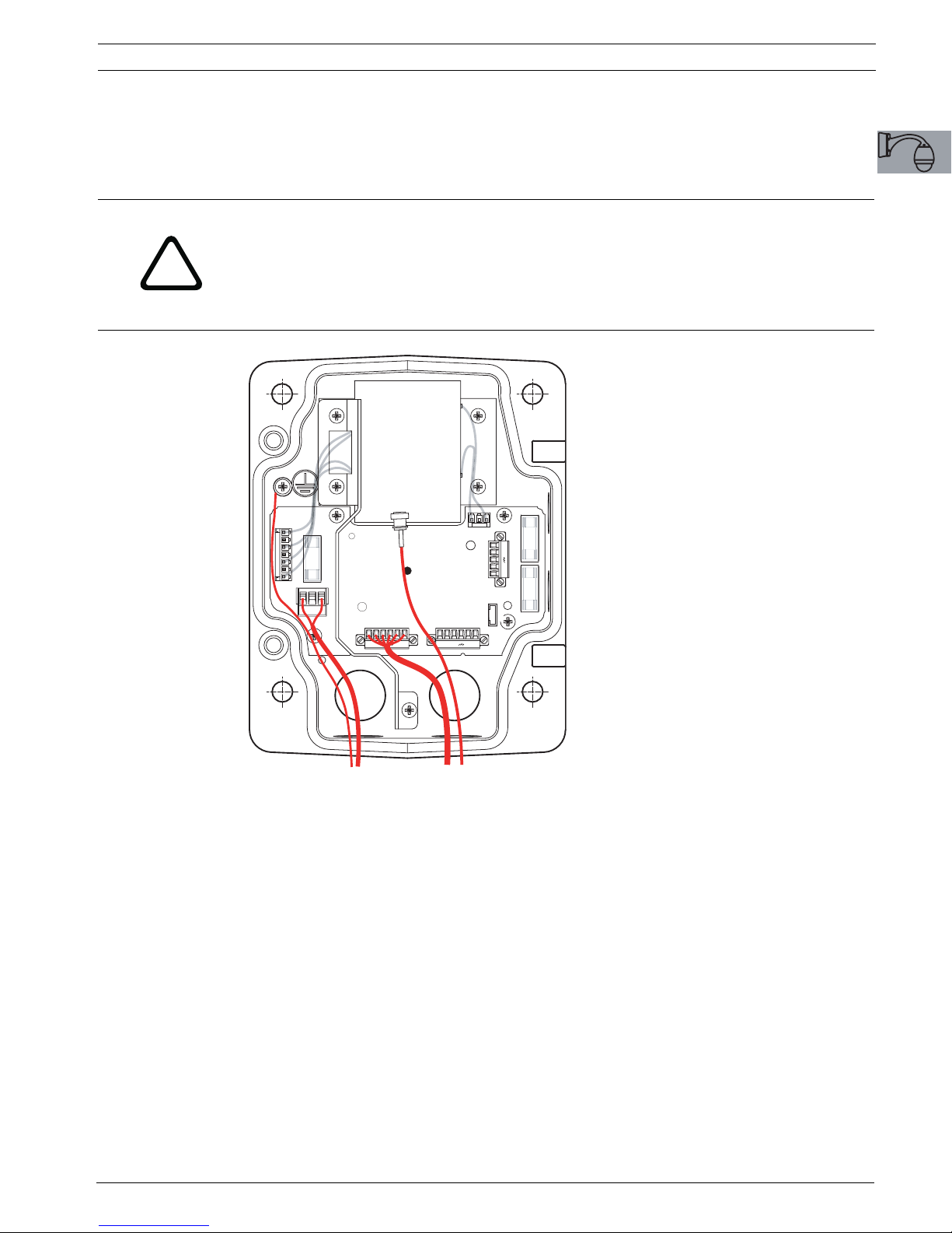
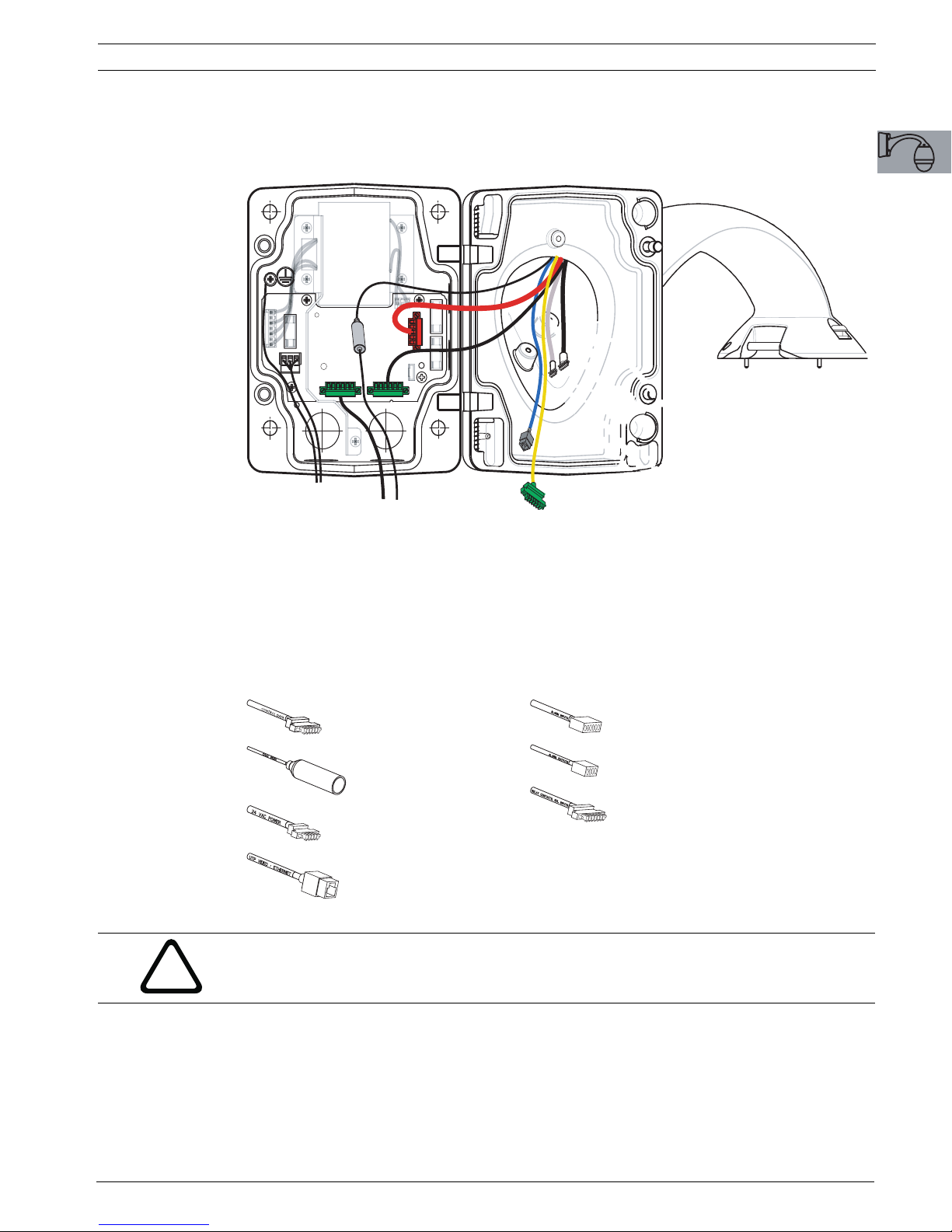
1.4 Route Wires and Attach Connectors
Power wires must be routed to the left (front) side of the Power Supply Box through a separate conduit. All video, control, and alarm wires must be routed through a second conduit to
the right side of the box.
WARNING! External interconnecting cables are to be installed in accordance to NEC,
ANSI/NFPA70 (for US application) and Canadian Electrical Code, Part I, CSA C22.1 (for CAN
application) and in accordance to local country codes for all other countries.
!
Branch circuit protection incorporating a 20 A, 2-pole Listed Circuit Breaker or Branch Rated
Fuses are required as part of the building installation. A readily accessible 2-pole disconnect
device with a contact separation of at least 3 mm must be incorporated.
J101
J102
24 VAC
FX101
P101
LINE NC NEUT
P106 P105
GND TXD RXD C+ C-GND TXD RXD C+ C-
P107
(LED)
5 4 3 2 1
HN HL N L
J103
XF102 XF103
Fig. 1.3 Pendant Arm Power Supply Box
1. Route all video, control, and alarm wires through the conduit fitting on the right side of
the power box. See Chapter 4: Cable and Wire Standards for coax, UTP, and fiber optic
specifications and distances.
2. Route the high voltage 115/230 VAC lines through the conduit fitting on the left side of
the box. The Power Supply Box with a transformer comes with a barrier that separates
the high voltage side on the left, from the low voltage 24 VAC side on the right.
3. Cut and trim all wires with sufficient slack to reach their connector terminals in the box,
but not so long as to be pinched by or to obstruct closing the Pendant Arm. See
Figure 1.5 on page 9 for the connector locations.
4. Attach the supplied 3-pin Power Plug to the incoming power wires. See connector P101
in Table 1.1 on page 9 for wire connections.
Bosch Security Systems, Inc. Installation Manual F01U010921 | 1.0 | 2006.10
8 en | Installing the Pendant Arm Wall, Corner, and Mast (Pole) Mounts AutoDome Modular Camera System
5. Attach the supplied 6-pin Control Data I/O Plug to the incoming control wires. See connector P106 in Table 1.1 on page 9 for wire connections. This step is not required with
Fiber Optic models, since control passes through the fiber optic cable.
NOTICE! If “daisy chaining” a series of AutoDomes, a terminating resistor is required in the
last dome of the series. The Bosch Power Supply Box is supplied with a 110 Ω terminating
resistor located between the biphase terminals C- and C+ (pins 1 and 2) of the P106 control
connector. Remove the resistor from all but the last AutoDome power box. The maximum
i
number of AutoDomes that can be daisy chained is four (4). If using the RS485 protocol for
control, the terminating resistor must be moved from the Biphase C+ and C- (pins 1 and 2)
terminals to the RXD- and TXD+ terminals (pins 4 and 5) of the P106 control connector of the
last AutoDome power box.
6. Attach a BNC connector to the incoming video coax cable. If using UTP for video or
installing an Ethernet model, attach an RJ45 plug to the incoming UTP cable. If installing
a Fiber Optic model, attach an ST fiber plug to the optic fiber cable. See Chapter 4: Cable
and Wire Standards for the different methods of transmitting video and control protocols,
and wire specifications.
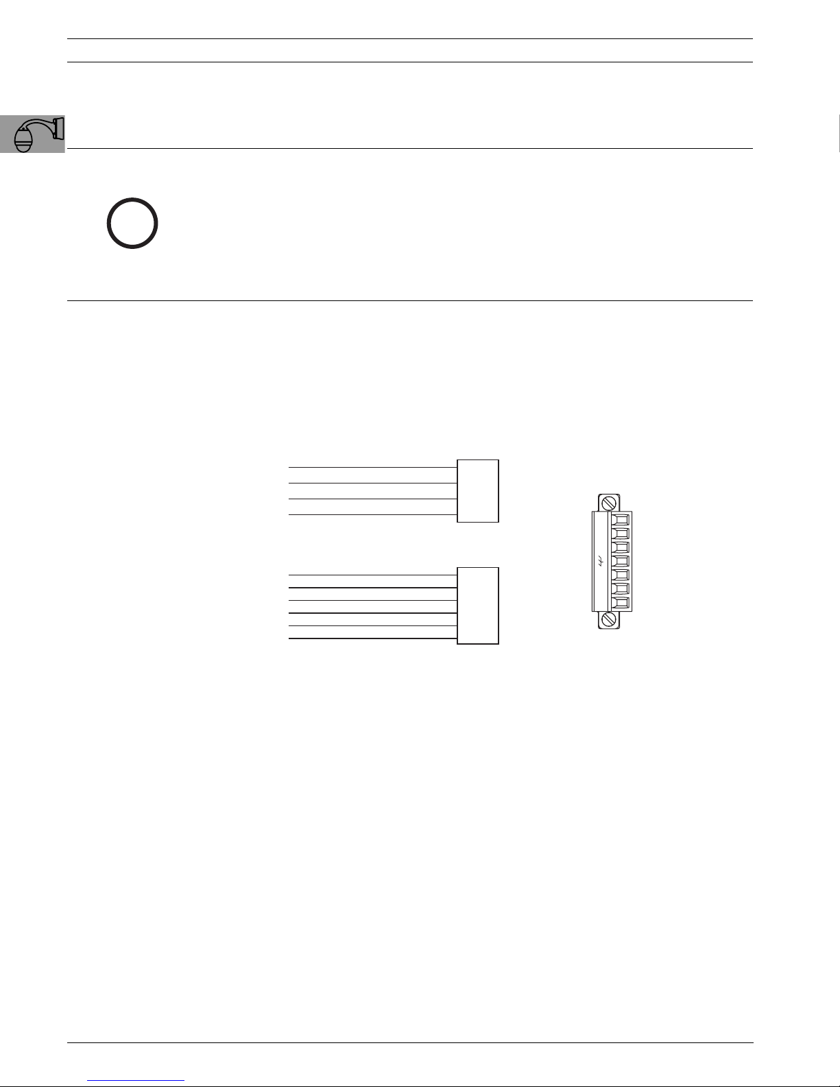
7. If you are connecting alarm inputs and outputs, attach the supplied 4- and 6-pin Alarm
Connectors with flying lead wires to the appropriate incoming alarm wires.
ALARM OUT 1
ALARM OUT 2
ALARM OUT 3
ALARM GROUND
ALARM IN 3
ALARM IN 4
ALARM IN 5
ALARM IN 6
ALARM IN 7
ALARM GROUND
* Low Voltage TTL (3.3V) can also be used.
Fig. 1.4 Alarm and relay connectors
WHITE
BROWN
ORANGE
GREEN
WHITE
BROWN
ORANGE
GREEN
YELLOW
BLUE
4-PIN
ALARM OUT
CONNECTOR
6-PIN
ALARM IN
CONNECTOR
7-PIN RELAY CONNECTOR
N.O. COM
N.C.
A1 GND
A2
1- N.O.
2- COM
3- N.C.
4- EARTH GROUND
5- ANALOG ALARM 1
6- ANALOG ALARM 2
7- GROUND
8. If you are connecting supervised alarms and relays, attach the supplied 7-pin Relay Connector to the appropriate incoming wires. See Figure 1.4, above, for the wire connections. See Chapter 5: Alarms and Relay Connections for more details about wiring alarms
and relays.
F01U010921 | 1.0 | 2006.10 Installation Manual Bosch Security Systems, Inc.
AutoDome Modular Camera System Installing the Pendant Arm Wall, Corner, and Mast (Pole) Mounts | en 9
(
C
)
J10
J
1
)
)
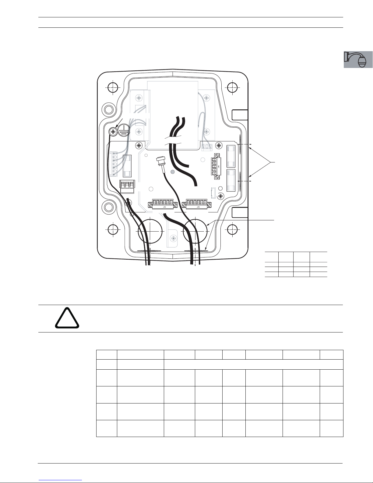
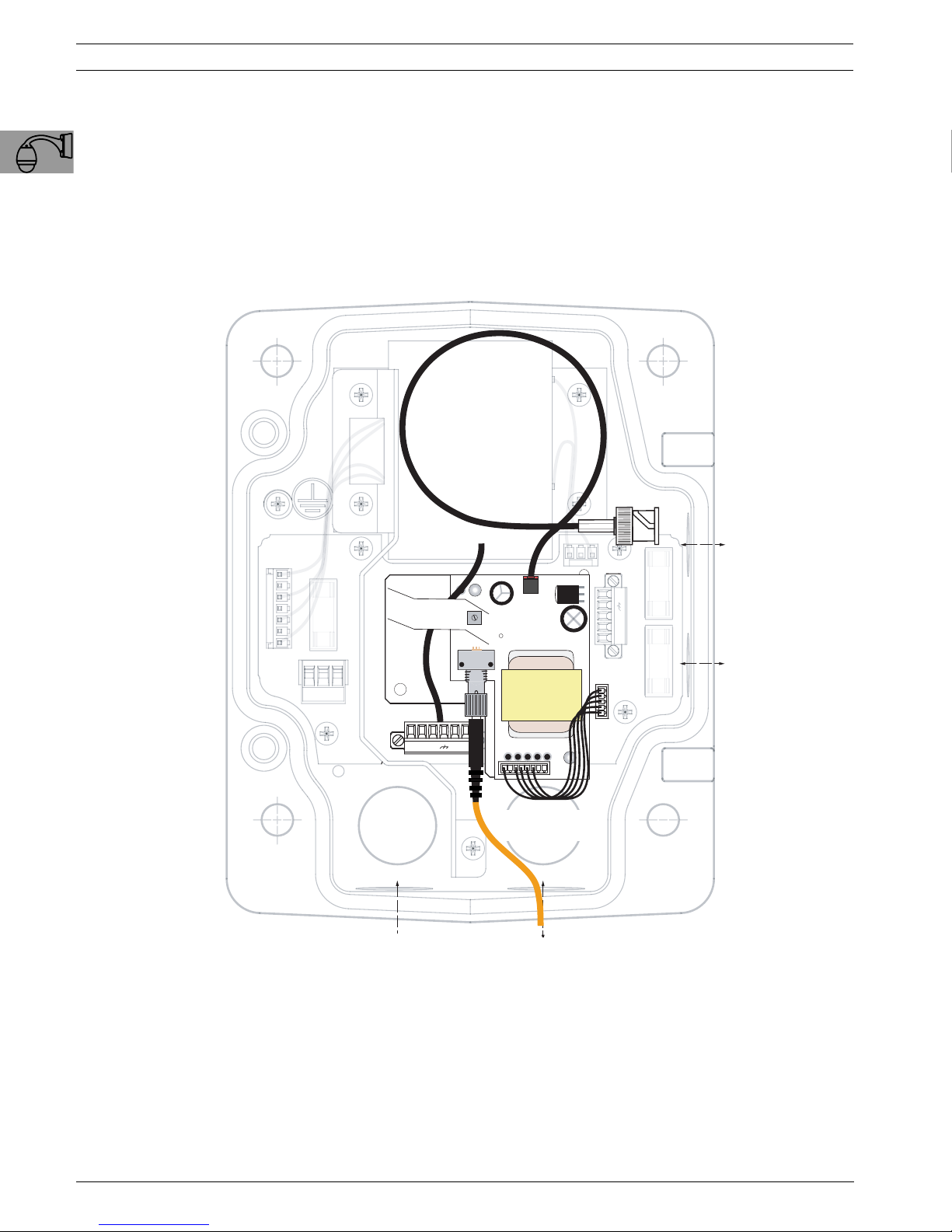
1.4.1 Power Supply Box Connections
The following figure is a detailed illustration of the Pendant Arm Power Supply Box, which
includes the fuse specifications.
TRANSFORMER
115/230VA
(GROUND SCREW)
MODELS
10
FUSE)
FX101
P101
POWER
IN
LINE NC NEUT
1 2 3
(FROM ARM HARNESS)
VIDEO
CONTROL
IN/OUT
P106 P105
6 5 4 3 2 1 6 5 4 3 2 1
Power In
POWER IN
2
24VAC
TO DOME
CONTROL
TO DOME
GND TXD RXD C+ C-GND TXD RXD C+ C-
Control Data
CONTROL DATA
and Video IN/OUT
AND VIDEO IN/OUT
P107
(LED)
5 4 3 2 1
HN HL N L
XF102 XF103
FUSE
FUSE
IN/OUT
IN/OUT
1/2 in. NPS FITTING
(15 mm)
IN/OUT
IN/OUT
3/4 in. NPS FITTING
(20 mm)
FUSE SPECIFICATIONS
VOLTS XF101 XF102 XF103
MAINS HEATER CAMERA
24 V T 5.0A T 3.15A T 2.0A
115 V T 1.6A T 3.15A T 2.0A
230 V T 0.8A T 3.15A T 2.0A
Fig. 1.5 Pendant arm power supply box
WARNING! Fuse replacement by qualified service personnel only. Replace with same type
fuse.
!
The following table lists the Power Supply Box connectors:
No. Connector Pin 1 Pin 2 Pin 3 Pin 4 Pin 5 Pin 6
Ground Grounding Screw
P101 115/230 VAC or 24
VAC Power In
P105 Control to Dome
(Arm Harness)
P106 Control In/Out C-
P107 24 VAC Power
(Arm Harness)
Table 1.1 Power Supply Box Connections
Bosch Security Systems, Inc. Installation Manual F01U010921 | 1.0 | 2006.10
Line NC Neutral
C(Biphase)C+(Biphase)
Earth
Ground
Earth
(Biphase)C+(Biphase)
Dome
24 VAC
Dome
24 VAC
Ground
Earth
Ground
RXD (+)
(RS-232/485)
RXD (+)
(RS-232/485)
Heater
(24 VAC)
TXD (-)
(RS-232/485)
TXD (-)
(RS-232/485)
Heater
(24 VAC)
Signal
Ground
Signal
Ground
10 en | Installing the Pendant Arm Wall, Corner, and Mast (Pole) Mounts AutoDome Modular Camera System
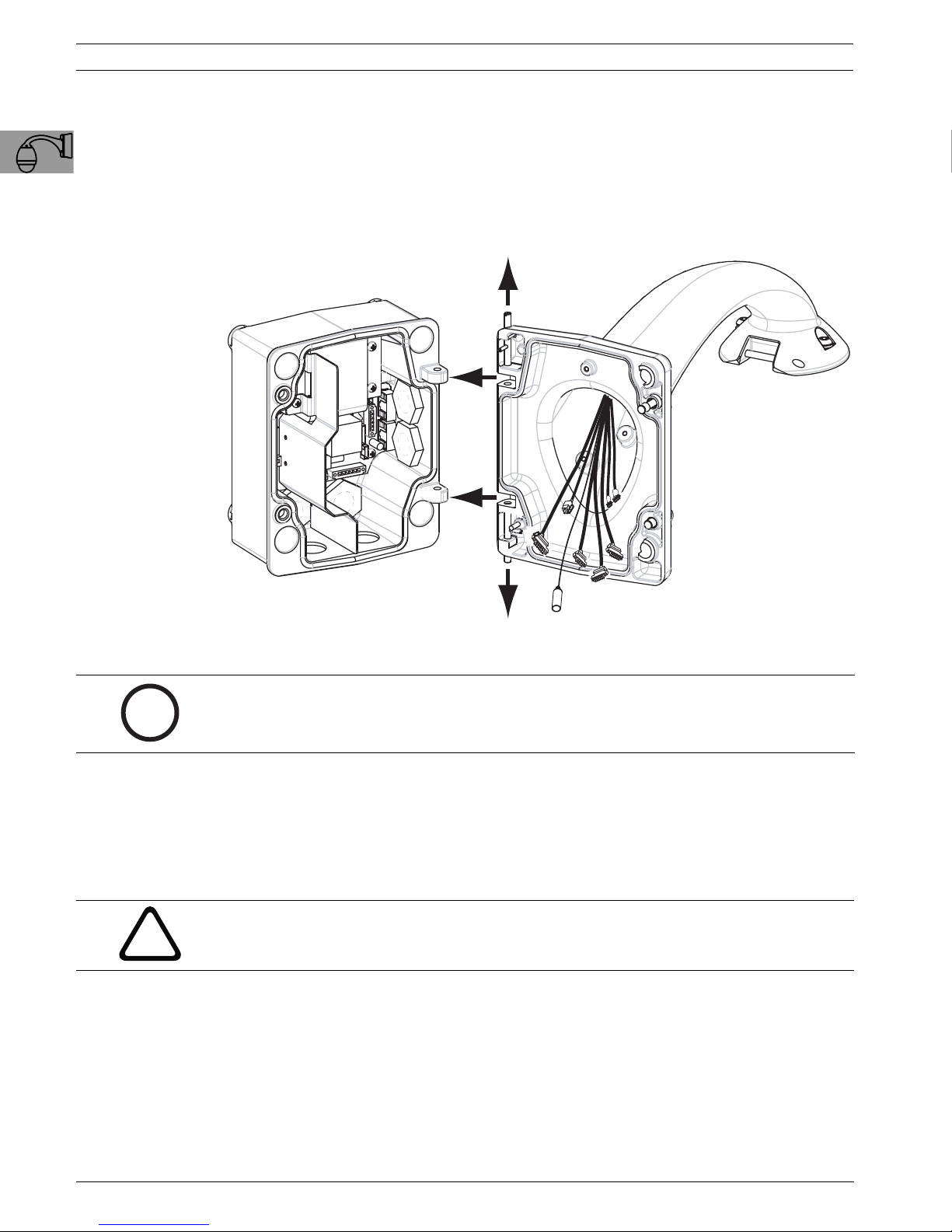
1.5 Attach Pendant Arm to Power Supply Box
The bottom hinge pin of the Pendant Arm is provided with a Hinge Pin Stop to hold the hinge
open while attaching the arm to the Power Supply Box.
1. Compress the bottom hinge pin by pushing the pin lever downward and rotating it behind
the Hinge Pin Stop.
i
POWER SUPPLY BOX
Power Supply Box
Fig. 1.6 Pendant Arm to Power Box Hinge Alignment
2. Open the top hinge by pushing its pin lever up and holding it.
NOTICE! Both Hinge Pins must be fully compressed to open (unlock) the hinges of the
Pendant Arm and before proceeding to the next step.
PENDANT ARM
Pendant Arm
3. While continuing to hold the top hinge pin open and align the top and bottom hinges of
the Pendant Arm to their mating points on the Power Supply Box. See Figure 1.6, above,
for an illustration.
4. Once you have the hinges aligned, release the top hinge pin to engage its mating hinge on
the power box. Then release the bottom hinge pin from the Hinge Pin Stop to lock the
Pendant Arm to the Power Supply Box.
WARNING! Serious injury or death can occur if the hinge pins of the Pendant Arm are
!
F01U010921 | 1.0 | 2006.10 Installation Manual Bosch Security Systems, Inc.
not fully engaged (locked) to the Power Supply Box. Exercise caution before
releasing the Pendant Arm.
AutoDome Modular Camera System Installing the Pendant Arm Wall, Corner, and Mast (Pole) Mounts | en 11
1.6 Make Connections in Power Supply Box
Refer to Figure 1.5 on page 9 to locate the various connectors in the power supply box and
make the following connections detailed below.
1 2 3
Fig. 1.7 Pendant Arm connections to Power Supply Box
1. Attach the earth ground wire to the grounding screw on the left side of the power box.
2. Connect the 6-pin Control In/Out Plug, installed previously, to its mating connector P106
in the power box. If this product is a Fiber Optic model this step is not required, since all
control data is sent through the fiber cable.
3. Connect the 6-pin Control to Dome Plug from the Pendant Connector Harness to its matting connector P105 in the power box. (For Fiber Optic model connect to the P106 connector.)
ALARM INPUTS
CONTROL DATA
Control Data
COAX VIDEO
Coax Video
24 VAC POWER
24 VAC Power
UTP/Ethernet Video
UTP/ETHERNET VIDEO
Fig. 1.8 Pendant Arm Harness Connectors
WARNING! Do not connect the RJ45 connector unless using UTP video or Ethernet.
Alarm Inputs
ALARM OUTPUTS
Alarm Outputs
RELAYS
Relays
!
4. Connect the 5-pin, 24 VAC to Dome Plug from the Pendant Connector Harness to its corresponding color mating connector P107 on the right side of the box.
5. Connect the incoming video coax cable to the BNC connector from the Pendant Connector Harness and slide its plastic cover over the connector.
Bosch Security Systems, Inc. Installation Manual F01U010921 | 1.0 | 2006.10
12 en | Installing the Pendant Arm Wall, Corner, and Mast (Pole) Mounts AutoDome Modular Camera System
)
T
T
HN HL N LINE
)
6. To connect alarm inputs and relay outputs, connect the 4-pin Alarms Out, the 6-pin
Alarms In and the 7-pin Relay connectors from the Pendant Connector Harness to their
mating connectors, installed previously, to the incoming alarm wires.
7. Connect the 3-pin Power In Plug, installed previously, to its matting connector P101 on
the left side of the box.
8. If installing a Fiber Optic model attach the incoming ST fiber plug, installed previously, to
its mating connector on the Fiber Optic Module in the power supply box. Then attach the
video BNC plug to its mating connector from the Pendant Connector Harness. See
Chapter 4: Cable and Wire Standards for fiber optic specifications.
(TRANSFORMER)
BNC TO DOME
(GND
FROM ARM
FUSE
LINE NC NEUT
Fig. 1.9 Optional Fiber Optic Module
HARNESS
GND TXD RXD C+ C-
Power In
POWER IN DATA IN/OUT
ST CONNECTOR
(FIBER)
Data IN/OUT
FUSE)
FUSE)
IN/OUT
IN/OU
IN/OUT
IN/OU
9. If using UTP for video or Ethernet, connect the incoming RJ45 video connector, installed
previously, to its mating connector from the Pendant Connector Harness. See Chapter 4:
Cable and Wire Standards for connections and specifications.
10. After making the harness connections to the Power Supply Box, rotate the Pendant Arm
to close and seal the Power Supply Box and tighten the two (2) captive screws to
10-12 N-m (90-105 in.-lbs).
F01U010921 | 1.0 | 2006.10 Installation Manual Bosch Security Systems, Inc.
AutoDome Modular Camera System Installing the Pendant Arm Wall, Corner, and Mast (Pole) Mounts | en 13
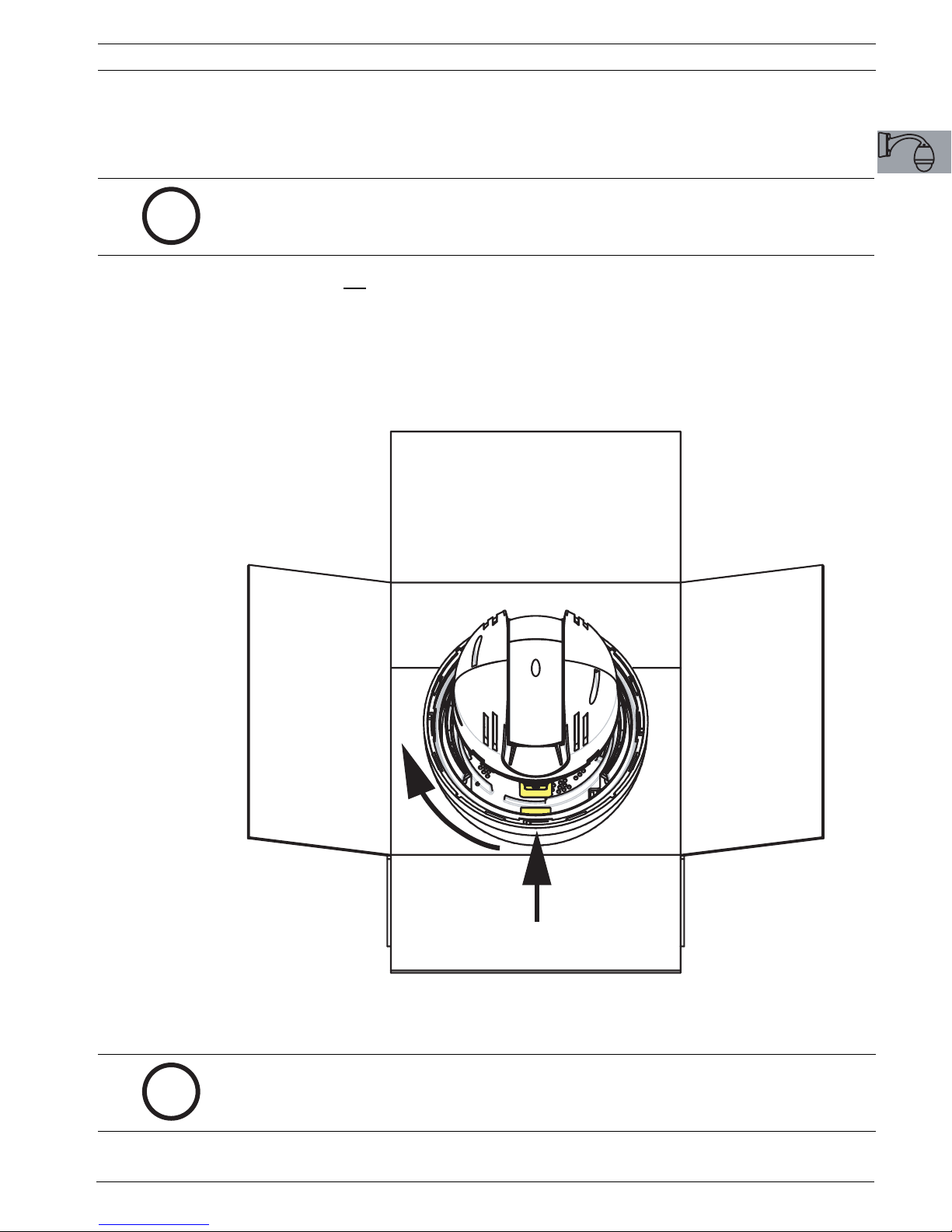
1.7 Assemble Pendant in Packing Box
The AutoDome Pendant must be assembled before attaching it to the roof or pipe mount. The
Pendant includes a Housing, Camera Module, and Bubble.
NOTICE! The Pendant Housing box is designed to hold the Pendant Housing in-place during
the assembly of the Pendant.
i
1. Open the top
inserts.
2. Remove the plastic bag from the Pendant Housing, and place the housing back into the
packing box.
3. Remove the Camera Module from its packing box and remove the protective plastic bag.
4. Align the yellow locking tab on the base of the Camera Module to the yellow label on the
CPU board and gently seat the camera into its connector.
of the box containing the Pendant Housing, and remove the two cardboard
Fig. 1.10 Align and Attach Camera Module
5. Rotate the yellow locking tab of the Camera Module clockwise (approximately 60
degrees) until the Camera Module locks in place.
NOTICE! The Camera Module must be able to rotate freely when installed in the housing.
i
Bosch Security Systems, Inc. Installation Manual F01U010921 | 1.0 | 2006.10
14 en | Installing the Pendant Arm Wall, Corner, and Mast (Pole) Mounts AutoDome Modular Camera System
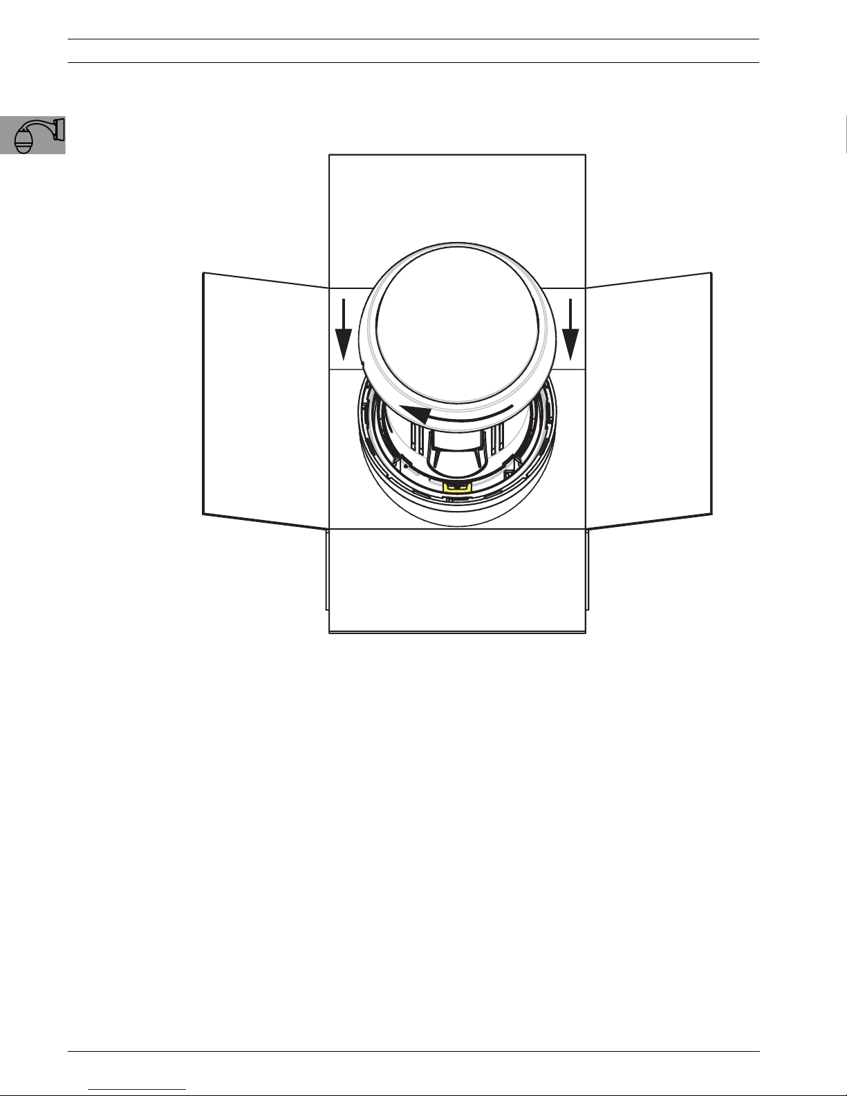
6. Remove the Bubble from its packing box, and remove the protective plastic bag.
7. Place the bubble over the Camera Module and rotate it clockwise (approximately 1/8
turn) until it locks in place. You will hear an audible click when it locks.
Fig. 1.11 Attach bubble
F01U010921 | 1.0 | 2006.10 Installation Manual Bosch Security Systems, Inc.
AutoDome Modular Camera System Installing the Pendant Arm Wall, Corner, and Mast (Pole) Mounts | en 15
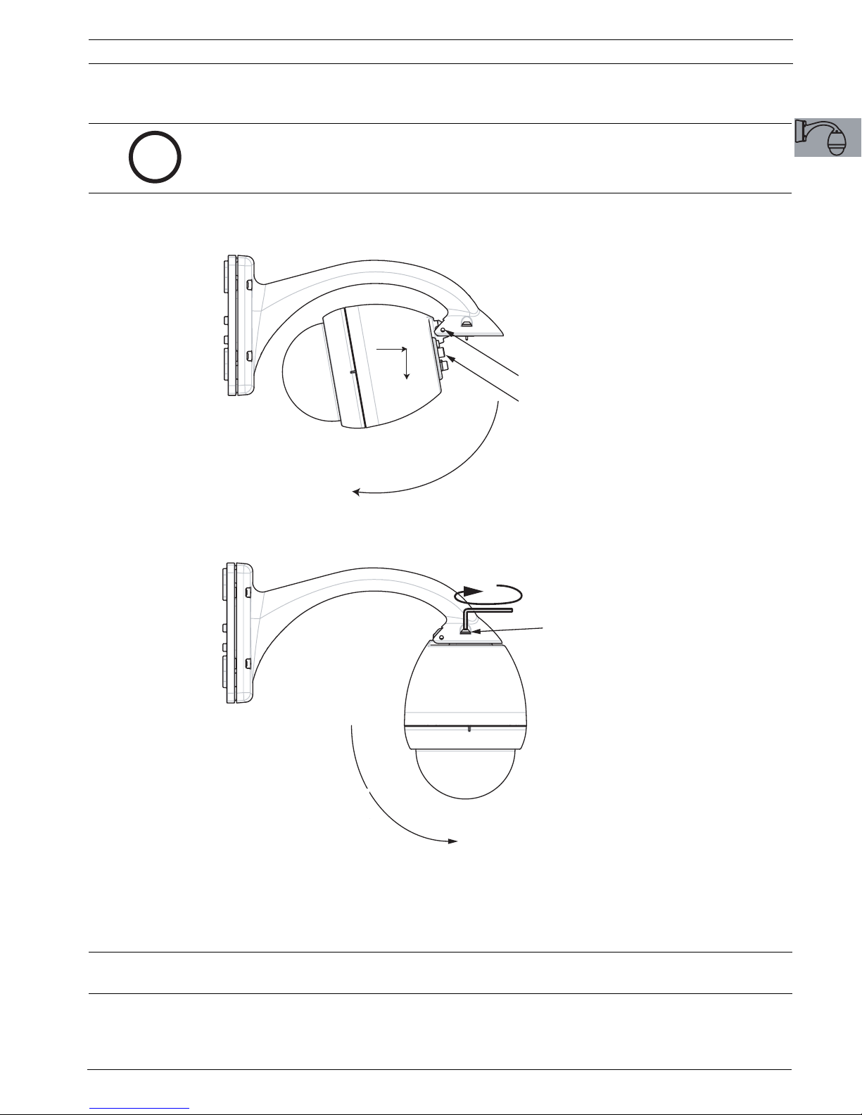
1.8 Attach Pendant to Arm and Tighten
NOTICE! Before attaching the AutoDome Pendant, visually inspect the dome and arm
connectors for any blocked pin holes or bent pins.
i
1. Tilt the bottom of the dome toward the pendant arm base and place the mounting hook,
located on top of the dome housing, over the recessed hinge pin of the arm.
2. Hook and
2. HOOK
Drop
AND DROP
Recessed Hinge Pin
RECESSED
HINGE PIN
Dome Connector
DOME CONNECTOR
1. Tilt Up
1. TILT UP
4. Tighten Two (2)
4. TIGHTEN TWO (2)
Mounting Screws
MOUNTING SCREWS
3. Rotate Down to
3. ROTATE DOWN
TO ENGAGE
Engage Dome
DOME CONNECTOR
Connector
Fig. 1.12 AutoDome to Pendant Arm Attachment
2. Drop the dome housing down slightly to engage the dome housing hook on the Pendant
Arm hinge pin, allowing the dome to rotate around the pin.
3. Rotate the dome housing down to a vertical position and gently push upward to engage
the connector on top of the dome housing.
CAUTION! If you feel any resistance when rotating the dome housing or when engaging the
connector, stop immediately and start over.
4. Hold the Pendant housing in position while tightening the two (2) 5-mm Allen head
mounting screws on top of the housing to 10-12 N-m (90-105 in.-lbs).
Bosch Security Systems, Inc. Installation Manual F01U010921 | 1.0 | 2006.10
16 en | Installing the Pendant Arm Wall, Corner, and Mast (Pole) Mounts AutoDome Modular Camera System
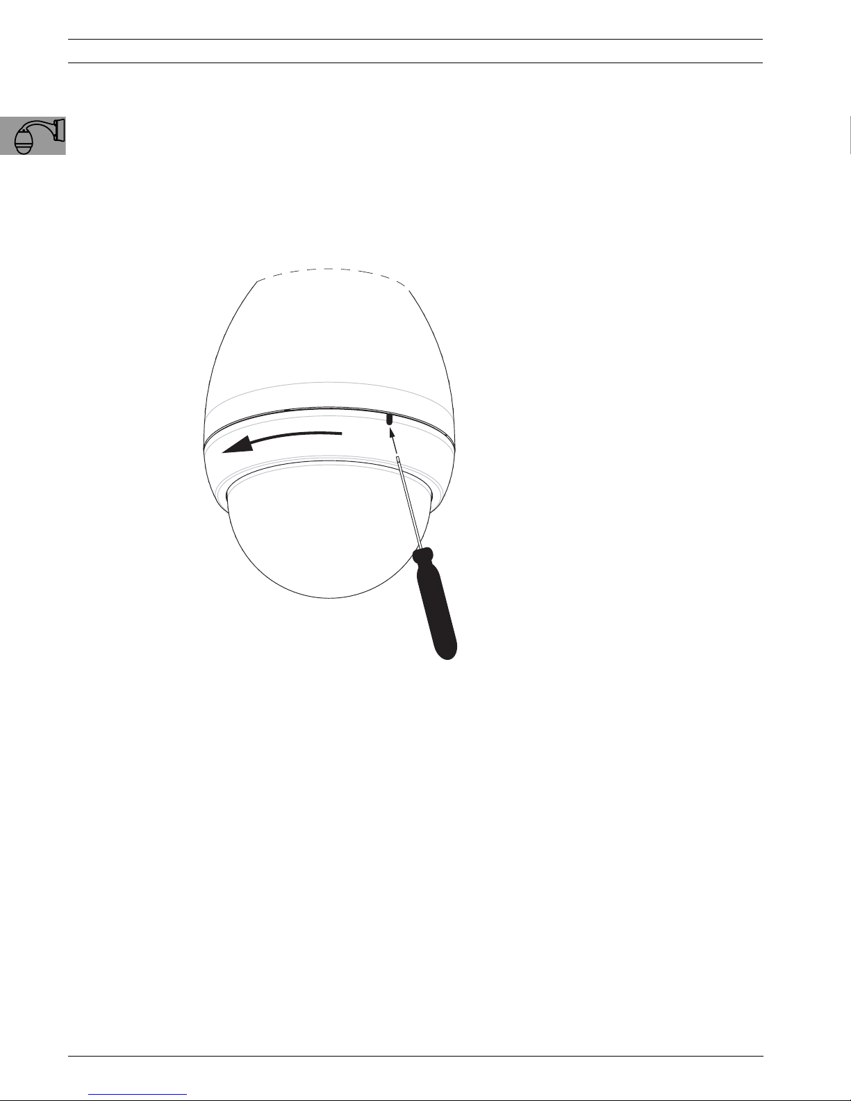
Removing the Pendant Bubble
To service the AutoDome Pendant, use the following procedure to remove the Bubble:
1. Using both hands, apply a counterclockwise (looking up at the dome) rotational force on
the Pendant Bubble Assembly to set the bubble latch.
2. Insert a small (2 mm) straight blade screw driver into the bubble release opening in the
bubble trim-ring to release the lock, and then remove the screwdriver. See the figure
below.
3. Rotate the Bubble Assembly counterclockwise approximately 20 degrees until the bubble
assembly releases from the Pendant Housing.
Fig. 1.13 Pendant Bubble Release Opening
F01U010921 | 1.0 | 2006.10 Installation Manual Bosch Security Systems, Inc.
 Loading...