


NIT3065

Cooktop
Model:
NIT3065...
NIT5065...
Nl'r5665...
NIT8065...
NIT8655...
BOSCH
Installation instructions 3 - 13
Instructions d'installation 14 - 24
Instrucciones de instalaci6n . . . . . . . . . . . . 25- 35
Table of contents
Important Safety Instructions ......................................
Before you begin .................................................
Tools and parts needed .............................................
Parts included .....................................................
Preparation .......................................................
Installation procedure .............................................
Installing the heat shield .............................................
Secure the cooktop to countertop ....................................
Electrical installation ................................................
Test the installation .................................................
Technical service .................................................
4
5
5
5
6
9
9
10
11
12
13
3
Important Safety Instructions
READ AND SAVE THESE INSTRUCTIONS
Impo_ant
SAVE THESE INSTRUCTIONS FOR LOCAL INSPECTOR'S USE
THIS APPLIANCE MUST BE INSTALLED BY A QUALIFIED TECHNICIAN
LEAVE THESE INSTRUCTIONS WITH THE APPLIANCE AFTER INSTALLATION IS
COMPLETE.
WARNING: If the information inthis manual is not followed exactly, fire or
shock may result causing property damage or personal injury.
WARNING: Do not repair or replace any part of the appliance unless
specifically recommended in the manual. Never modify or alter the
construction of the appliance.
Improper installation, technical service or maintenance can cause injury or
property damage. Refer to this manual. Consult with a factory authorized
service center for all repairs.
Remove all tape and packaging before using the appliance. Destroy the packaging
after unpacking the appliance. Never allow children to play with packaging material.
Safe appliance handling Hidden surfaces may have sharp edges. Use caution when reaching behind or
under appliance.
Electrical safety Before installing, turn off at the service panel. Lock service panel to prevent power
from being turned on accidentally.
The circuit breaker should have a contact separation of at least 3 mm. on all poles.
Be sure your appliance is properly installed and grounded by a qualified technician.
Have the installer show you the location of the circuit breaker or fuse. Mark it for
easy reference.
This appliance has been tested in accordance with ANSI/UL 858 Standard for
Safety for Household Electric Ranges and CAN/CSA-22.2 No. 61 National
Standard of Canada for Household Cooking Ranges. It isthe responsibility of the
owner and installer to determine if additional requirements and standards apply in
specific installations.
Related equipment safety This stove is guaranteed safefor use only if it is installed by a specialist pursuant to
the installation instructions. The installer is responsible for any damage caused due
to improper installation.
To eliminate the risk of burns or fire when touching hot surface units, avoid leaving
storage space in the cabinets over the surface units. Inthe event of presence of
storage in cabinets, the risk can be reduced by installing a hood that extends
horizontally at least 5 inches (12.7 cm) from the cabinet bottom.
Do not install refrigerators, dishwashers, unvented ovens, or washers that may fit
below the cooktop.
Note: We strongly recommend the installation of a ventilation system with this
appliance.
4
Before you begin
Tools and parts needed
÷ Phillips head screwdriver
÷ Pencil
÷ Drill with 1/4" (6.35 mm) bit
÷ Jigsaw
÷ Tape measure
Note: Additional materials may be necessary for installation in solid surface
countertops. Contact the countertop manufacturer.
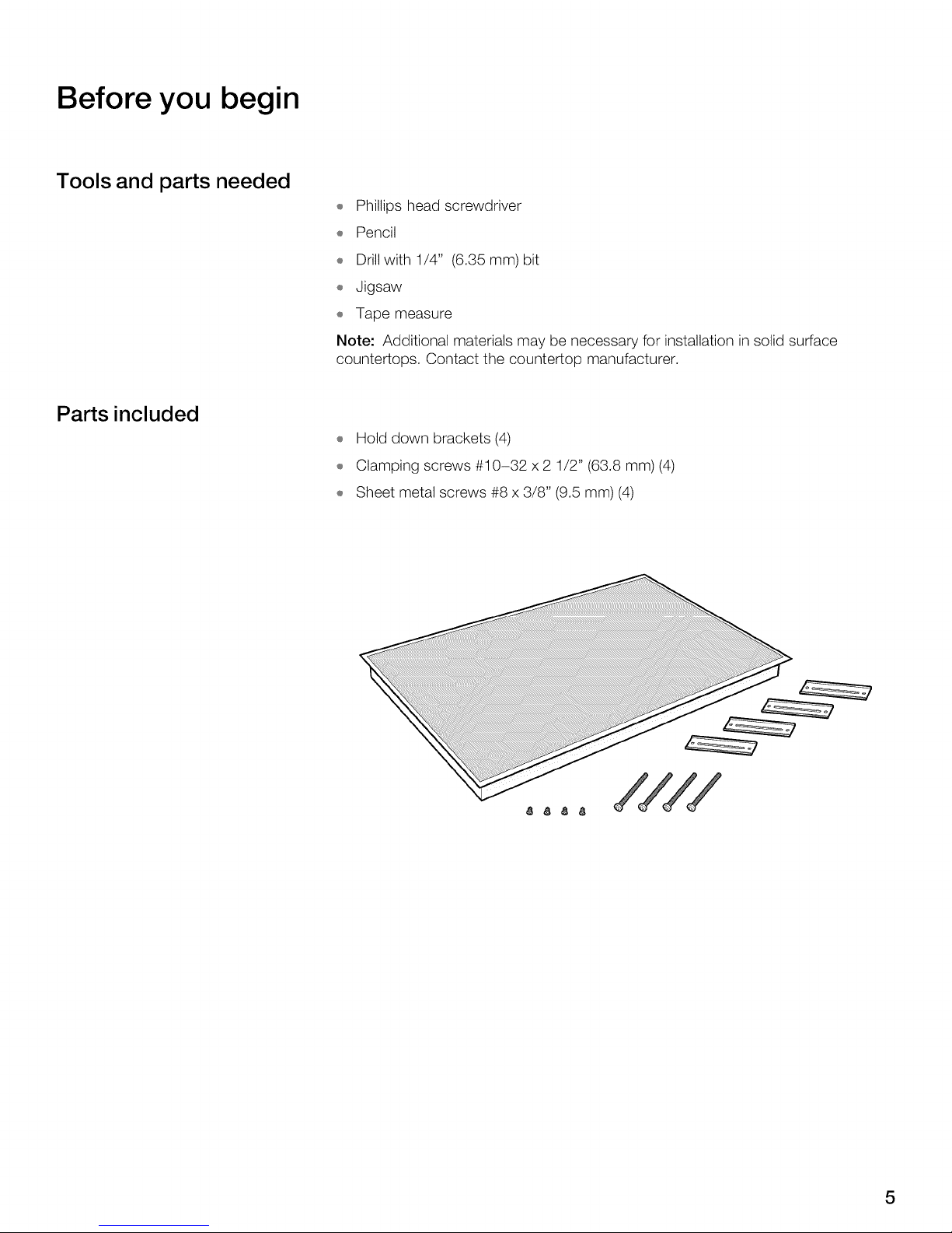
Parts included
÷ Hold down brackets (4)
÷ Clamping screws #10-32 x 2 1/2" (63.8 mm) (4)
÷ Sheet metal screws #8 x 3/8" (9.5 mm) (4)
////
5
Preparation
Countertop requirements
_ WARNING: To reduce the risk of ignition of nearby combustible materials,install the countertop with a minimum distance of 2" (51mm) from both side
walls and the back wall.
Note
The work surface should be horizontal and level. The stability of the countertop
should be confirmed even after making the cutout.
After preparing cutout, remove shavings as they can affect the function of electrical
components.
Seal the surfaces of the cutout to make them heat resistant. This prevents the
surfaces from expanding as a result of humidity.
Solid surface countertops often require special installation. For example, heat
reflective tape or rounded corners may be necessary. Contact the countertop
manufacturer for instructions specific to your countertop.
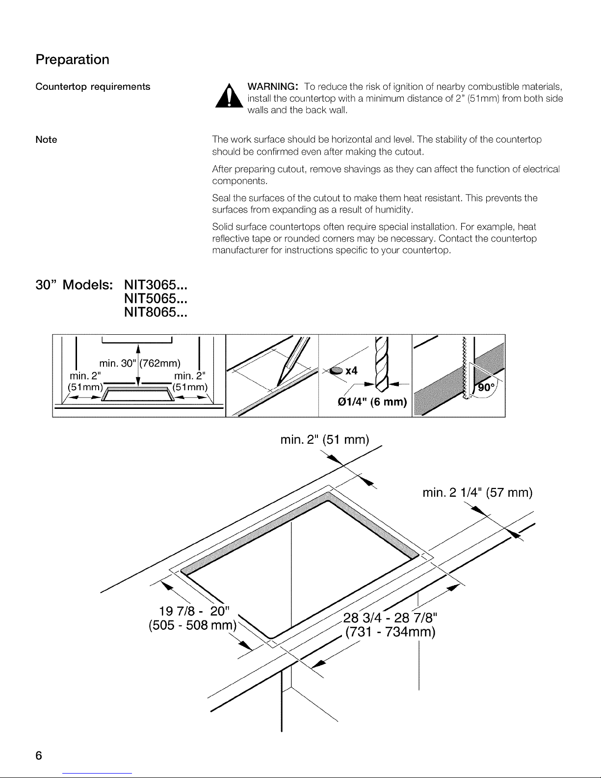
30" Models: NIT3065...
NIT5065...
NIT8065...
I . I
min"301(762mm)I
min. 2" _ min. 2"
I (51 mm) .... 51 mm)
min. 2" (51 mm)
min. 2 1/4" (57 mm)
19 7/8 - 2O"
(505 - 508 mm
.28 3/4 - 28 7/8"
(731 - 734mm)
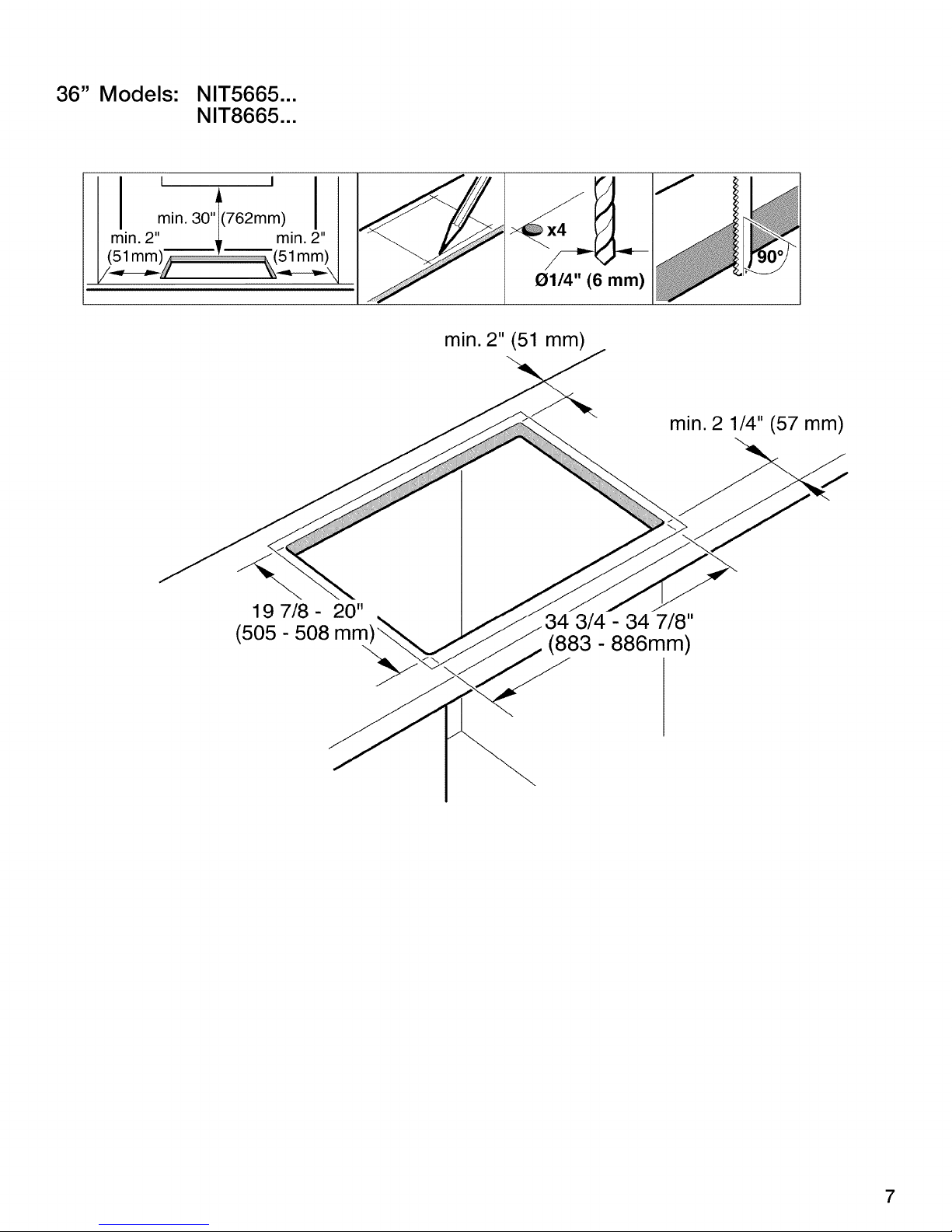
36" Models: NIT5665...
NIT8665...
I ,, I I
min" 30 1(762mm)I
min. 2" _ min. 2"
1/ // "\\ \
G11/4"(6 mm)
min. 2" (51 mm)
min. 2 1/4" (57 mm)
19 7/8 - 20"
(505 - 508 mm
3/4 - 34 7/8"
(883 - 886mm)
7
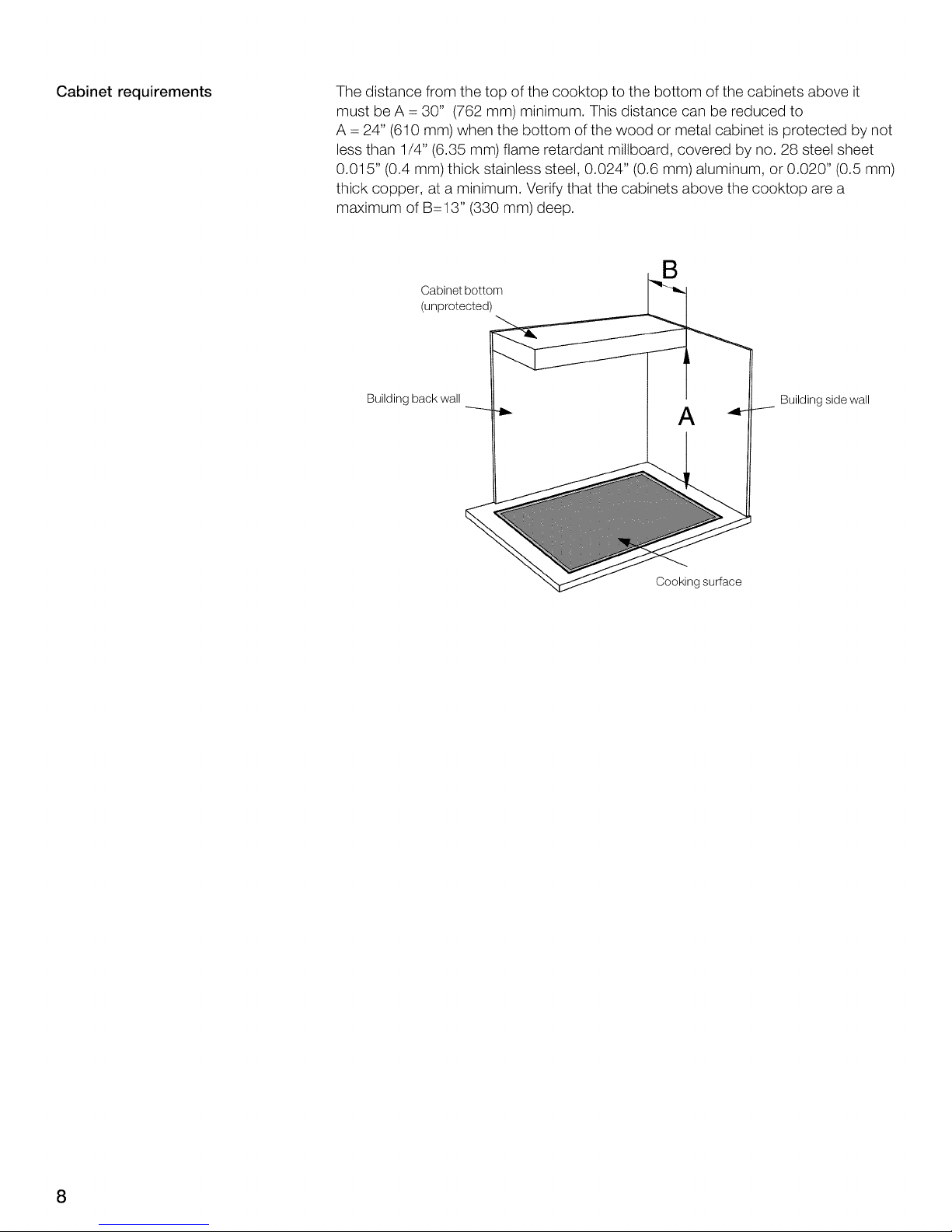
Cabinet requirements The distance from the top of the cooktop to the bottom of the cabinets above it
must be A -- 30" (762 mm) minimum. This distance can be reduced to
A -- 24" (610 mm) when the bottom of the wood or metal cabinet is protected by not
less than 1/4" (6.35 mm) flame retardant millboard, covered by no. 28 steel sheet
0.015" (0.4 mm) thick stainless steel, 0.024" (0.6 mm) aluminum, or 0.020" (0.5 mm)
thick copper, at a minimum. Verify that the cabinets above the cooktop are a
maximum of B--13" (330 mm) deep.
i Building side wall
Cooking surface
Installation procedure
_ WARNING: Use protective gloves when installing the plate.
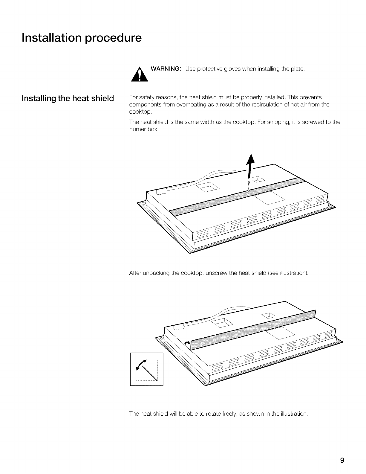
Installing the heat shield
For safety reasons, the heat shield must be properly installed. This prevents
components from overheating as a result of the recirculation of hot air from the
cooktop.
The heat shield is the same width as the cooktop. For shipping, it is screwed to the
burner box.
After unpacking the cooktop, unscrew the heat shield (see illustration).
The heat shield will be able to rotate freely, as shown in the illustration.
9
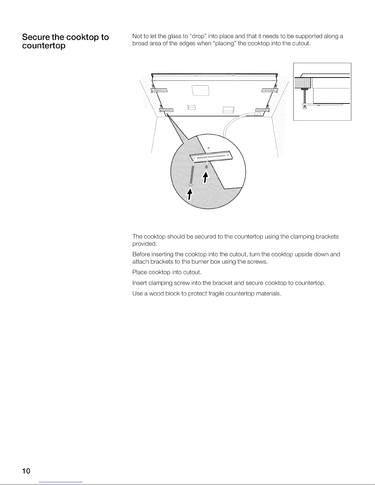
Secure the cooktop to
countertop
Not to let the glass to "drop" into place and that it needs to be supported along a
broad area of the edges when "placing" the cooktop into the cutout.
I
7
The cooktop should be secured to the countertop using the clamping brackets
provided.
Before inserting the cooktop into the cutout, turn the cooktop upside down and
attach brackets to the burner box using the screws.
Place cooktop into cutout.
Insert clamping screw into the bracket and secure cooktop to countertop.
Use a wood block to protect fragile countertop materials.
10
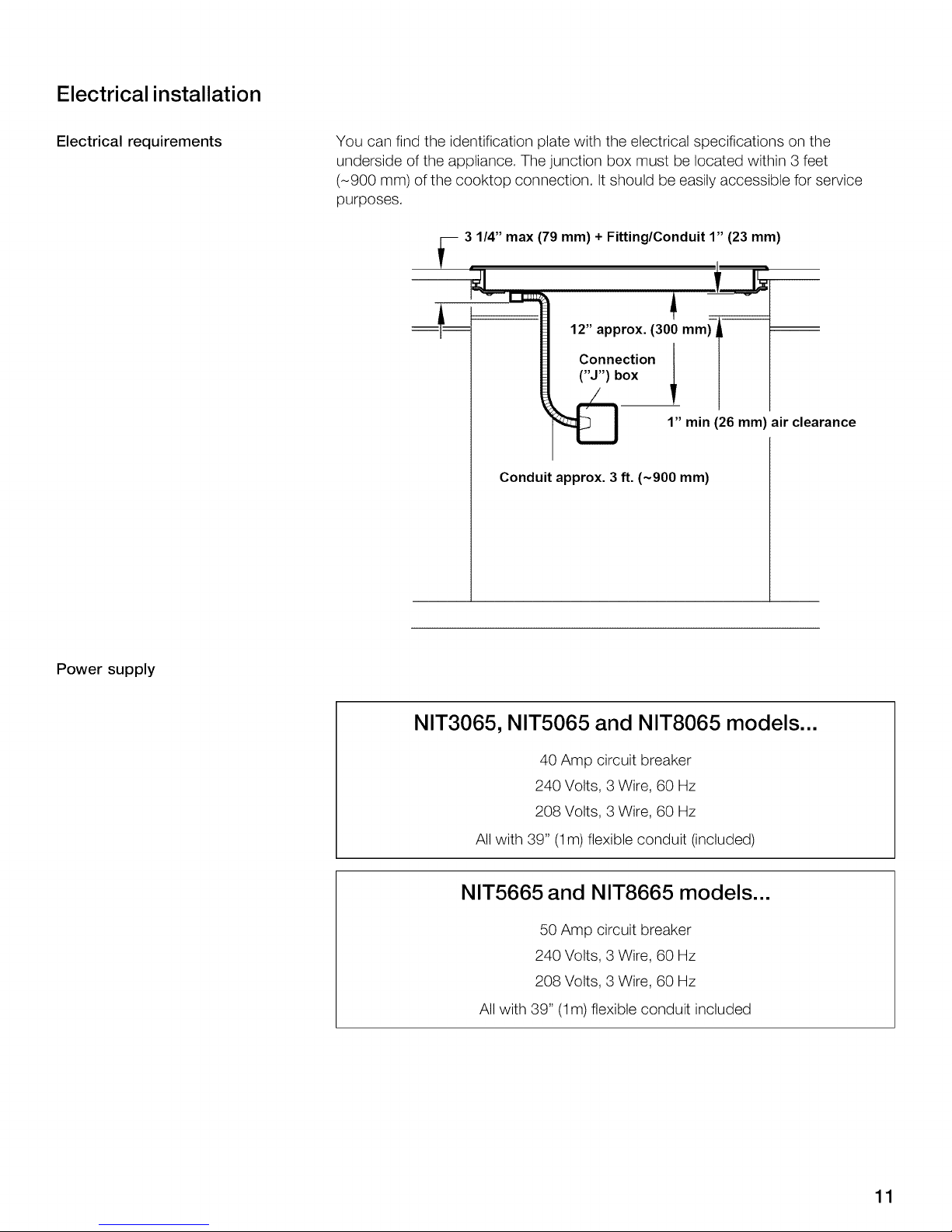
Electrical installation
Electrical requirements You can find the identification plate with the electrical specifications on the
underside of the appliance. The junction box must be located within 3 feet
(-900 mm) of the cooktop connection. It should be easilyaccessible for service
purposes.
3 1/4" max (79 mm) + Fitting/Conduit 1" (23 mm)
12" approx. (300 mm,_-A--
Connection
("J") box
_] 1" min (26 mm) air clearance
Conduit approx. 3 ft. (~900 mm)
Power supply
NIT3065, NIT5065 and NIT8065 models...
40 Amp circuit breaker
240 Volts, 3 Wire, 60 Hz
208 Volts, 3 Wire, 60 Hz
All with 39" (1m) flexible conduit (included)
NIT5665 and NIT8665 models...
50 Amp circuit breaker
240 Volts, 3 Wire, 60 Hz
208 Volts, 3 Wire, 60 Hz
All with 39" (1m) flexible conduit included
11
 Loading...