


 Loading...
LP Gas Conversion Kit
Installation Manual
NGM5456UC

Table of Contents |
|
Safety Definitions .......................................................... |
2 |
IMPORTANT SAFETY INSTRUCTIONS ........................ |
3 |
Gas Appliance Safety .......................................................... |
3 |
State of California Proposition 65 Warning: .................... |
4 |
Before You Begin .......................................................... |
5 |
Parts Included ....................................................................... |
5 |
Tools and Parts Needed ..................................................... |
5 |
Installation Procedure ................................................... |
5 |
Checklist ............................................................................... |
5 |
Step 1 - Convert the pressure regulator .......................... |
6 |
Step 2 - Replace the orifices ............................................. |
7 |
Step 3 - Replace the burners, burner caps |
|
and grates ............................................................................. |
8 |
Step 4 - Convert valves for LP gas ................................... |
9 |
Check Installation ....................................................... |
10 |
Test for gas leaks ............................................................. |
10 |
Check manifold gas pressure ........................................ |
10 |
Final check ......................................................................... |
10 |
Service ......................................................................... |
11 |
Before Calling Service ..................................................... |
11 |
7KLV %RVFK $SSOLDQFH LV PDGH E\ %6+ +RPH $SSOLDQFHV &RUSRUDWLRQ
0DLQ 6WUHHW 6XLWH ,UYLQH &$
4XHVWLRQV"
ZZZ ERVFK KRPH FRP XV
:H ORRN IRUZDUG WR KHDULQJ IURP \RX
Safety Definitions
9WARNING
This indicates that death or serious injuries may occur as a result of non-observance of this warning.
9CAUTION
This indicates that minor or moderate injuries may occur as a result of non-observance of this warning.
NOTICE: This indicates that damage to the appliance or property may occur as a result of non-compliance with this advisory.
Note: This alerts you to important information and/or tips.
2

9 IMPORTANT SAFETY INSTRUCTIONS
READ AND SAVE THESE INSTRUCTIONS
Gas Appliance Safety
:$51,1* ,I WKH LQIRUPDWLRQ LQ WKHVH LQVWUXFWLRQV LV QRW IROORZHG H[DFWO\ D ILUH RU H[SORVLRQ PD\ UHVXOW FDXVLQJ SURSHUW\ GDPDJH SHUVRQDO LQMXU\ RU GHDWK
²'R QRW VWRUH RU XVH JDVROLQH RU RWKHU IODPPDEOH YDSRUV DQG OLTXLGV LQ WKH YLFLQLW\ RI WKLV RU DQ\ RWKHU DSSOLDQFH
²:+$7 72 '2 ,) <28 60(// *$6'R QRW WU\ WR OLJKW DQ\ DSSOLDQFH'R QRW WRXFK DQ\ HOHFWULFDO VZLWFK'R QRW XVH DQ\ SKRQH LQ \RXU EXLOGLQJ
,PPHGLDWHO\ FDOO \RXU JDV VXSSOLHU IURP D QHLJKERU·V SKRQH )ROORZ WKH JDV VXSSOLHU·V LQVWUXFWLRQV,I \RX FDQQRW UHDFK \RXU JDV VXSSOLHU FDOO WKH ILUH GHSDUWPHQW
²,QVWDOODWLRQ DQG VHUYLFH PXVW EH SHUIRUPHG E\ D TXDOLILHG LQVWDOOHU VHUYLFH DJHQF\ RU WKH JDV VXSSOLHU
3

9 IMPORTANT SAFETY INSTRUCTIONS
READ AND SAVE THESE INSTRUCTIONS
BOSCH COOKTOP CONVERSION KIT FOR TRADITIONAL MODELS NATURAL GAS (NG) TO PROPANE (LP) GAS.
This kit is used to convert only NGM sealed burner cooktops from natural gas operation to propane gas operation. This kit cannot be used to convert other Bosch model sealed burner cooktops, ranges, or any other brand of cooktops.
WARNING
This conversion kit shall be installed by a qualified service agency in accordance with the manufacturer’s instructions and all applicable codes and requirements of the authority having jurisdiction. If the information in these instructions is not followed exactly, a fire, explosion or production of carbon monoxide may result causing property damage, personal injury or loss of life.
The qualified service agency is responsible for the proper installation of this kit. The installation is not proper and complete until the operation of the converted appliance is checked as specified in the manufacturer’s instructions supplied with the kit.
IMPORTANT: Only a qualified service technician or installer should make this conversion.
INSTALLER: Please leave these Conversion Instructions with this unit for the owner.
OWNER: Please retain these instructions for future reference.
For Massachusetts Installations:
1.Installation must be performed by a qualified or licensed contractor, plumber, or gas fitter qualified or licensed by the state, province or region.
2.Shut-off valve must be a “T” handle gas cock.
3.Flexible gas connector must not be longer than 36 inches.
CAUTION
When connecting the unit to the propane gas, make certain the propane gas tank is equipped with its own high pressure regulator. In addition, a pressure regulator was supplied with the cooktop. This second regulator must be installed with the cooktop. The maximum gas pressure to this appliance is not to exceed 14.0 inches water column from the propane gas tank regulator.
The following must be met when testing supply piping system:
a)The appliance and its individual shut-off valve must be disconnected from the gas supply piping system at test pressures in excess of 1/2 psig (3.5 kPa).
b)The appliance must be isolated from the gas supply piping system by closing its individual manual shut-off valve during any pressure testing of the gas supply piping system at test pressures equal to or less than 1/ 2 psig (3.5 kPa).
State of California Proposition 65
Warning:
WARNING
This product can expose you to chemicals including vinyl chloride, which is known to the State of California to cause cancer and birth defects or other reproductive harm. For more information go to
www.P65Warnings.ca.gov.
Note: IMPORTANT SAFETY NOTICE: The California Safe Drinking and Toxic Enforcement Act requires the Governor of California to publish a list of substances known to the state to cause cancer, birth defect or other reproductive harm, and requires businesses to warn customers of potential exposure to such substances. The burning of gas cooking fuel and the elimination of soil during self-cleaning can generate small amounts of carbon monoxide. The fiberglass insulation in Self Clean ovens gives off very small amounts of formaldehyde during the first several cleaning cycles. California lists formaldehyde as a potential cause of cancer. Carbon monoxide is a potential cause of reproductive toxicity. Exposure to these substances can be minimized by:
1.Providing good ventilation when cooking with gas.
2.Operating the unit according to the instructions in this manual.
4
Before You Begin
Parts Included
Installation kit contents |
|
|
|
|
Component |
|
Quantity |
||
|
|
|
|
|
Conversion Kit Instructions |
|
1 |
|
|
|
|
|
|
|
Conversion sticker |
|
1 |
|
|
|
|
|
|
|
Foam tape |
|
1 |
|
|
64 orifice |
|
2 |
|
|
|
|
|
|
|
75 orifice |
|
1 |
|
|
|
|
|
|
|
88 orifice |
|
1 |
|
|
Main orifices |
|
|
|
|
NGM5456UC |
BTU/hr |
kW |
|
|
|
|
|
|
|
64 |
Front right |
5,000 |
1.47 |
|
|
|
|
|
|
64 |
Front left |
5,000 |
1.47 |
|
|
|
|
|
|
75 |
Rear left |
7,000 |
2.05 |
|
88 |
Rear right |
10,000 |
2.93 |
|
|
|
|
|
|
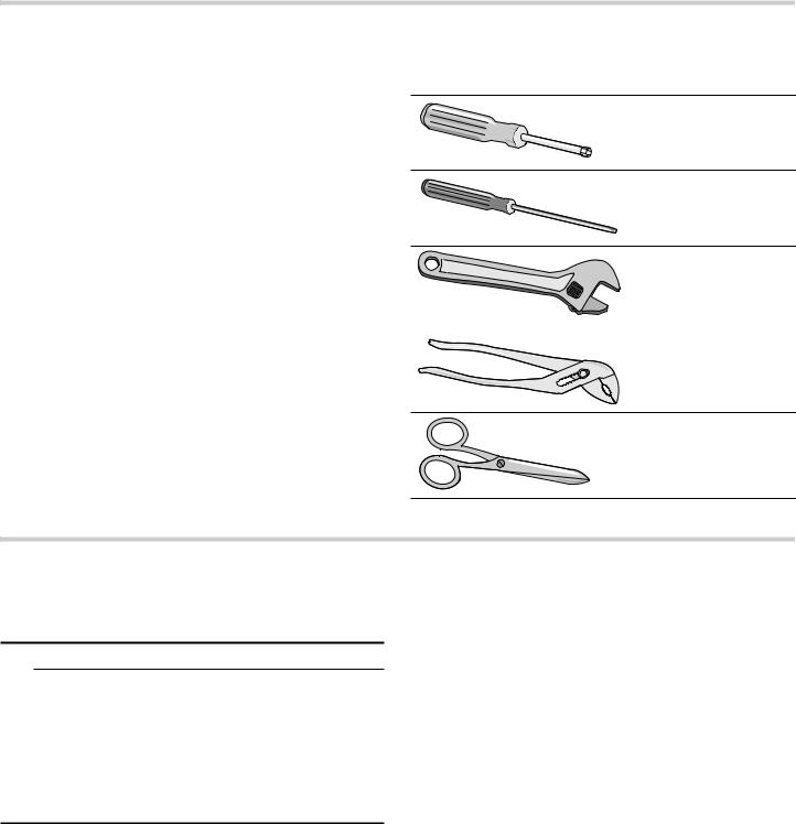
Tools and Parts Needed
7 mm socket driver
(3 inch minimum extension)
Flat blade screwdriver, small thin blade
Adjustable wrench and/or
slip joint pliers
Scissors
Installation Procedure
This conversion process adjusts the flow of gas to the burners to accommodate an LP gas fuel source.
9CAUTION
TURN OFF GAS AND ELECTRICITY
Perform the following:
shut off the gas valve for the gas supply line to the cooktop
remove the cooktop power cord from the electrical outlet or turn off the breaker at the breaker box.
turn all control knobs to the “Off” position.
Checklist
Each of the following steps must be completed correctly for the appliance to function properly.
Check off each step as it is finished.
ÙStep 1 |
Convert the pressure regulator to use |
|
LP gas. |
||
|
||
|
|
|
ÙStep 2 |
Remove the grates, burner caps and |
|
burners. Remove the Natural Gas (NG) |
||
|
||
|
orifices and replace them with the LP gas |
|
|
orifices supplied with this kit. |
|
|
|
|
ÙStep 3 |
Replace the burners, burner caps and |
|
grates. |
||
|
||
ÙStep 4 |
Adjust the unit valves to LP settings. |
|
|
||
|
|
5

Step 1 - Convert the pressure regulator
Locate the pressure regulator on the bottom right end of the cooktop.
Note: The arrow on the back of the regulator must point in the direction of the gas flow to the cooktop.
1.Remove the hexagon shaped cap from the regulator making sure not to dislodge the gasket on the cap or the spring inside the regulator.
2.Grasp the plastic button stem firmly and pull it forcefully from the metal cap. The stem snaps snugly into an indent in the cap and may require a strong pull to remove. (Hint: it may be helpful to gently “rock” the plastic stem while pulling it from the metal cap.)
%
$ 
&
ASpring
BPlastic button stem
CGasket
3.After removing the stem from the cap, rotate the stem 180° so the button end of the stem is away from the cap and the letters “LP” on the stem are upside down when the cap is set flat on its head. Snap the stem back in place in this position inserting it into the indent in the metal cap.The stem should snap into place.
4.Important: Attach the metallic sticker (included with this conversion kit) to the bottom of the appliance as shown, placing it near the appliance data plate (shows model number and information about the appliance). This sticker provides notice that the appliance has been converted for use with LP gas.
6

Step 2 - Replace the orifices
1.Remove the grates, burners and burner caps. Note: Remove the igniter from the unit.
2.Remove the orifices.
Notes
The orifices require a 7 mm socket driver for removal/replacement. The driver will need to be inserted approximately 2^" (64 mm) into the burner cavity to reach the orifice.
To reduce the chance of the orifice being dropped from the socket driver, add a piece of foam tape or adhesive tape inside the socket.
ATrim a small piece of the foam tape provided with this kit (about ]" x ^" / 6 mm x 12 mm)
BFit this so the tape wraps against one side of the socket so it stays in place.
CThe tape will fit to the orifice and help prevent the orifice from falling out of the socket during extraction.
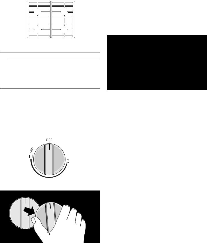
3.Identify the correct placement of the LP gas orifices as layed out on the orifice package card.
The orifice sizes corresponding to each burner are shown in the following image. These numbers are engraved on the top of each orifice. It is very important to install the correct orifice size for each burner.
1*0 8&
5
Save the NG orifices in case there is need later to restore the appliance to use natural gas again.
2)) |
2)) |
2)) |
2)) |
+, |
+, |
+, |
+, |
/2 |
/2 |
/2 |
/2 |
4 4
4.Insert each of the LP gas orifices provided with this kit into the socket (using the small piece of foam tape to ensure a tight fit).
ACheck to be sure the small piece of foam tape used earlier is fitted to wrap against one side of the socket.
BWhen pressing the socket driver onto the orifice, the tape will help the orifice fit more snugly inside the socket. This will help prevent the orifice from falling out of the socket during
insertion.
7

Step 3 - Replace the burners, burner caps and grates
Replace the burners, burner caps and grates. Be sure the grates are correctly placed and the rubber feet on the grates engage the indents in the cooktop for proper position.
Burner Cap and Burner Base Placement
9WARNING
To prevent flare-ups, do not use the cooktop without all burner caps and all burner grates properly positioned.
9WARNING
To prevent burns, do not touch burner caps or grates while hot. Turn the cooktop off and allow the burners to cool.
The burner caps must be properly placed for the cooktop to function properly. If the burner cap is not properly placed, one or more of the following problems may occur:
Burner flames are too high.
Flames shoot out of burners.
Stainless steel discolors.
Burners do not ignite.
Burner flames light unevenly.
Burner emits gas odor.
Burner Cap and Burner Base Placement
After electrical connection is complete, place each burner base on the corresponding location on the cooktop. One of the three bars on the burner base should line up with the notch and prevent the base from rotating. The small hole or cutout near the edge should also line up with the igniter. Pay special attention to avoid damaging the igniter during installation of the base. See Illustration below.
Once each base is located and resting evenly, place each burner cap on its correct burner base. See Illustration.
Place burner cap gently on top of base so that the prongs of the burner base fit snugly into the groove of the burner cap.
If the maintop is removed by a certified installer (for example to check electrical or piping connection) the panhead screws that were removed must be reinstalled to ensure proper functionality of burners.
1 |
2 |
Placing Burner Caps and Bases
Checking Burner Cap Placement
Check to make sure that there is no gap between the burner cap and burner base. See illustration below for correct and incorrect placements of the burner cap.
You may gently try to move the burner cap from side to side to check if it is properly placed. If properly placed, the cap will click from side to side as the prongs hit the groove ridge.
Checking Burner Cap Placement
8
Install Burner Grates
Properly position and install each burner grate as shown in the illustration below.
3.Your appliance has hollow stem valves.
Locate the correct point of insertion for the long, thin flat blade screwdriver to adjust the bypass jet (see the following illustration).
AHollow stem valve - insert a long, thin flat blade screwdriver in the hollow stem of the valve. The adjustment screw is approximately 1^" (39 mm)
from the top of the stem. The screwdriver slides through a thin rubber barrier in the stem (helps prevent damage in the case of a spill on the unit surface).
24” 4 Burner
9WARNING
To prevent flare-ups, properly support pots and avoid spills, all grates must be properly positioned on the cooktop whenever the cooktop is in use. Do not use a grate if the rubber feet are missing or damaged.
For replacement of rubber feet: Call Customer Support at 1-800-944-2904.
Step 4 - Convert valves for LP gas
The bypass jet on each valve must be adjusted. Your cooktop has hollow valve shafts. Determine the bypass screw location accordingly.
1. Turn all knobs to the “OFF” position.
2. Remove knobs.
4.Engage the tip of the screwdriver into the adjustment screw by slowly turning the screwdriver and feeling for the blade to engage the screw. Then turn the screw clockwise about 70 degrees (less than 1/4 turn) until it “bottoms out” (does not turn any further). The screw does not take much pressure to turn. Stop when the screw does not easily turn any further. Repeat for each valve until all have been adjusted correctly.
5.Replace the knobs.
9

Check Installation
Test for gas leaks
9WARNING
NEVER TEST FOR GAS LEAKS USING A FLAME
If any leaks are detected, do not proceed past this step until all leaks have been eliminated.
Leak testing is to be conducted by the installer according to the instructions given in this section.
Turn on gas. Apply a non-corrosive leak detection fluid to all joints and fittings in the gas connection between the shutoff valve and the cooktop. Include gas fittings and joints in the cooktop if connections may have been disturbed during installation. Bubbles appearing around fittings and connections indicate a leak. An electronic Gas Leak Detector can also be used.
If a leak appears, turn off the supply line gas shutoff valve and tighten the leaking connections. Retest for leaks by turning on the supply line gas shutoff valve.
When the leak check is complete (no bubbles appear), the test is complete. Wipe off all detection fluid residue.
Check manifold gas pressure
During any pressure testing of the gas supply piping system at test pressures greater than 14" of water column pressure (approximately ½" psig, 3.5 kPA) it is necessary to disconnect the cooktop and its individual shut-off valve from the gas supply piping system.
If it should be necessary to check the manifold gas pressure, connect a manometer (water gauge) or other approved gas pressure reading device to the top burner right rear orifice. Using a rubber hose with inside diameter of approximately 1/4" hold tubing down tight over orifice. Turn burner valve on.
Final check
After conversion is complete, place each correct sized burner cap in its seated, notched position and check the operation of the electric igniters. Check flame characteristics. Flame should be blue with a minimal yellow tip on the outer cone of the flames.
Check flame characteristics
Yellow flames:
Further adjustment is required.
Yellow tips on outer cones:
Normal for LP Gas.
Soft blue flames:
Normal for Natural Gas.
If the flame is completely or mostly yellow, verify that the regulator is set for the correct fuel. After adjustment, retest.
Some yellow streaking is normal during the initial startup. Allow unit to operate 4 to 5 minutes and reevaluate before making adjustments.
10
Service
Before Calling Service
If the igniters do not spark or the “on” indicator lights (available in some models) do not glow, check the power source to see if a fuse has blown or if the circuit breaker has tripped.
Refer to the Statement of Limited Warranty in the Use and Care Manual. See the Use and Care Manual for troubleshooting information.
Product Rating Label
The rating label shows the model number and the FD number (production number/product’s unique identifier) of your cooktop. It is located on the underside of the cooktop.
$
Rating Label Location
A Rating Label
Model number and FD Number
The model number and the FD number of your appliance are found on the rating label. Make a note of these numbers in the space below to save time in the event your appliance requires service.
Model # |
FD # |
|
|
Bosch Customer Support |
800-944-2904 |
|
|
Keep your invoice or escrow papers for warranty validation if service is needed.
11
Loading...