


 Loading...
Bosch NIT5068UC, NIT5668UC, NIT8068SUC, NIT8068UC, NIT8668UC Installation Instructions
...Cooktop
Installation Manual
NIT5068UC, NIT8068SUC, NIT8068UC, NITP068SUC, NITP068UC, NIT5668UC, NIT8668SUC, NIT8668UC, NITP668SUC, NITP668UC
Table of Contents |
|
Safety Definitions .......................................................... |
2 |
IMPORTANT SAFETY INSTRUCTIONS ........................ |
3 |
Safety Codes and Standards ............................................. |
3 |
Electric Safety ....................................................................... |
3 |
Related Equipment Safety .................................................. |
3 |
State of California Proposition 65 Warnings ................... |
3 |
Before you begin ........................................................... |
4 |
Tools and parts needed ...................................................... |
4 |
Parts included ....................................................................... |
4 |
Cabinet Requirements ......................................................... |
4 |
Countertop Requirements .................................................. |
4 |
Prepare Installation Space ........................................... |
5 |
Cutout dimensions for 30" cooktops ............................... |
5 |
Cutout dimensions for 36" cooktops ............................... |
6 |
Ventilation .............................................................................. |
6 |
Installation Procedure .................................................. |
7 |
Installing the heat shield ..................................................... |
7 |
Secure the cooktop to countertop .................................... |
7 |
Electrical Installation .................................................... |
8 |
Electrical requirements ....................................................... |
8 |
Connect Electrical Supply .................................................. |
8 |
Check the Installation .......................................................... |
9 |
Customer Service .......................................................... |
9 |
Safety Definitions
9WARNING
This indicates that death or serious injuries may occur as a result of non-observance of this warning.
9CAUTION
This indicates that minor or moderate injuries may occur as a result of non-observance of this warning.
NOTICE: This indicates that damage to the appliance or property may occur as a result of non-compliance with this advisory.
Note: This alerts you to important information and/or tips.
2

9 IMPORTANT SAFETY INSTRUCTIONS
READ AND SAVE THESE INSTRUCTIONS
IMPORTANT: The appliance must be installed by a qualified installer.
INSTALLER: please leave these instructions with this unit for the owner. Show the owner the location of the circuit breaker or fuse. Mark it for easy reference.
OWNER: Please retain these instructions for future reference.
WARNING
If the information in this manual is not followed exactly, fire or shock may result causing property damage or personal injury.
WARNING
Do not repair, replace or remove any part of the appliance unless specifically recommended in the manuals. Improper installation, service or maintenance can cause injury or property damage. Refer to this manual for guidance. All other servicing should be done by an authorized servicer.
Remove all tape and packaging before using the appliance. Destroy the packaging after unpacking the appliance. Never allow children to play with packaging material.
Hidden surfaces may have sharp edges. Use caution when reaching behind or under appliance.
This appliance is intended for use up to a maximum height of 13,100 feet (4,000 meters) above sea level.
Improper installation is not covered by the warranty.
Safety Codes and Standards
This appliance complies with one or more of the following Standards:
UL 858, The Standard for the Safety of Household
Electric Ranges
UL 507, The Standard for the Safety of Electric Fans
CAN/CSA-C22.2 No. 113-M1984 Fans and Ventilators
CAN/CSA-C22.2 No. 61-M89 Household Cooking Ranges
It is the responsibility of the owner and the installer to determine if additional requirements and/or standards apply to specific installations.
Electric Safety
WARNING
Before you plug in an electrical cord or turn on power supply, make sure all controls are in the OFF position.
If required by the National Electrical Code (or Canadian Electrical Code), this appliance must be installed on a separate branch circuit.
The circuit breaker should have a contact separation of at least 3 mm on all poles.
Be sure your appliance is properly installed and grounded by a qualified technician. Installation, electrical connections and grounding must comply with all applicable codes.
Before installing, turn power OFF at the service panel. Lock service panel to prevent power from being turned ON accidentally.
WARNING
IMPROPER GROUNDING CAN RESULT IN A RISK OF ELECTRIC SHOCK
Consult a qualified electrician if the grounding

 instructions are not completely understood, or if doubt exists as to whether the appliance is properly grounded. DO NOT USE AN
EXTENSION CORD.
Related Equipment Safety
The appliance should only be used if installed by a qualified technician in accordance with these installation instructions. The manufacturer is not responsible for any damage resulting from incorrect installation.
Never modify or alter the construction of the appliance. For example, do not remove leveling legs, panels, wire covers or anti-tip brackets/screws.
To eliminate the risk of burns or fire by reaching over heated surface units, cabinet storage space located above the surface units should be avoided. If cabinet storage is to be provided, the risk can be reduced by installing a hood that projects horizontally a minimum of 5 inches (127 mm) beyond the bottom of the cabinet.
Verify that cabinets above the cooktop are a maximum of 13" (330 mm) deep.
DO NOT install refrigerators, dishwashers, ovens (without ventilation), or washing machines below the Cooktop.
Note: We strongly recommend the installation of a ventilation system with this appliance.
State of California Proposition 65 Warnings
WARNING
This product can expose you to chemicals including vinyl chloride, which is known to the State of California to cause cancer and birth defects or other reproductive harm. For more information go to
www.P65Warnings.ca.gov.
3
Before you begin
Tools and parts needed
Phillips Head Screwdriver
Pencil
Drill with ¼" (6 mm) bit
Jigsaw
Tape Measure
Note: Additional materials may be necessary for installation in solid surface countertops. Contact the countertop manufacturer.
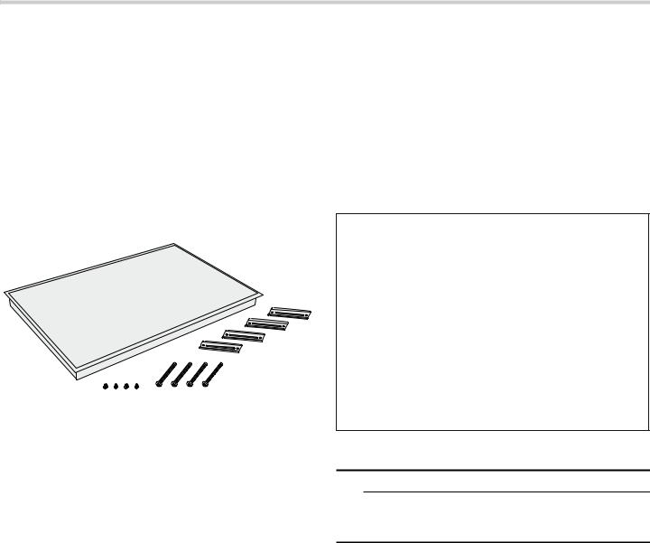
Parts included
Hold down brackets (4)
Clamping screws #10-32 x 2 ^" (63.8 mm) (4)
Sheet metal screws #8 x \" (9.5 mm) (4)
Cabinet Requirements
The distance from the top of the cooktop to the bottom of cabinets above must be a minimum of A=30" (762 mm) min. This distance can be reduced to A=24" (610 mm) when the bottom of the wood or metal cabinet is protected by not less than ¼" (6.35 mm) flame-retardant millboard covered with not less than no. 28 gauge sheet metal, 0.015" (0.4 mm) stainless steel, 0.024" (0.6 mm) aluminum or 0.020" (0.5 mm) copper.
Verify that the cabinets above the cooktop are a maximum of B=13" (330 mm) deep.
%
$
Countertop Requirements
9WARNING
To reduce the risk of ignition of surrounding combustible materials, install at least 2" (51 mm) from both sidewalls and the rear wall.
The countertop must be level and horizontal. The stability of the countertop must be maintained after the cut-out has been made.
Solid surface countertops often require special installations. For example, heat-reflective tape and rounded corners may be necessary. Contact the countertop manufacturer for instructions specific to your countertop.
4
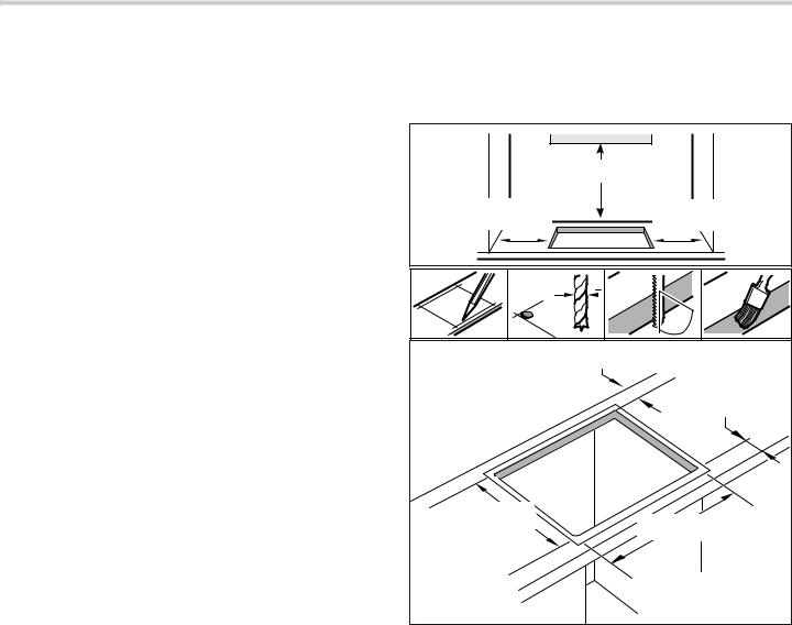
Prepare Installation Space
Create the cut-out in the countertop according to the installation diagram. The angle of the cut surface to the countertop must be 90°.
The lateral cut-out edges must be flat in order to ensure that the retaining springs are positioned properly on the appliance. With multi-layered countertops, secure strips laterally in the cut-out if necessary.
After creating cut-out, remove shavings. Seal cut surfaces in a heatand water-resistant manner.
Observe minimum distance between device underside and cabinet surfaces of 3/8" (10 mm).
The worktop into which the cooktop is installed must be heat-resistant up to 140° F (90 °C).
The worktop must be reinforced if it is less than 4/5 inch (20 mm) thick.
If the thickness of the worktop into which the cooktop is installed does not comply with the specifications, reinforce the worktop using a fireand water-resistant material until it reaches the minimum thickness. Otherwise, sufficient stability cannot be assured.
The worktop into which the cooktop is installed should withstand loads of approx. 133 lbs (60 kg).
Only check the evenness of the cooktop after it has been installed.
Cutout dimensions for 30" cooktops
Models: NIT5068UC, NIT8068SUC, NIT8068UC, |
|
NITP068SUC, NITP068UC |
|
PLQ PP |
|
PLQ |
PLQ |
PP |
PP |
¡ |
|
PP |
|
[ |
|
|
|
|
PLQ PP |
|
PLQ PP |
|
|
PP |
|
|
PP |
5

Cutout dimensions for 36" cooktops
Models: NIT5668UC, NIT8668SUC, NIT8668UC, |
||
NITP668SUC, NITP668UC |
|
|
PLQ PP |
||
PLQ |
PLQ |
|
PP |
PP |
|
¡ |
|
|
PP |
|
|
[ |
|
|
|
||
PLQ PP |
||
|
PLQ PP |
|
|
|
|
PP |
||
PP |
||
|
||
Ventilation |
|
|
To assure that the appliance works correctly, the cooktop MUST be sufficiently ventilated.
Since the ventilation in the lower section of the appliance requires a sufficient supply of fresh air, the cabinet must be designed accordingly. The following is required for this:
A minimum clearance between the rear of the cupboard and the kitchen wall, and between the surface of the worktop and the upper area of the drawer.
PLQ |
|
PLQ æʌ¼ʕʔ |
|
|
PP |
An opening at the top to the rear of the cupboard.
PLQ èè¼ʓʘ
PLQ ë
PP
If the minimum clearance of 25/32 inch (20 mm) is not provided at the rear of the cupboard, you must create an opening on the underside.
PLQ æʌ¼ʕʔ
PP
If the inside of the cupboard is no wider than 29 1/2 inch (750 mm), make cutouts in the side panels.
PLQ 
$ê
PP
Note: If the appliance is installed in an island unit or another installation that is not described here, you must ensure that the cooktop is sufficiently ventilated.
6

Installation Procedure
9CAUTION
Sharp edges. Use protective gloves when installing the cooktop.
Note: The appliance is heavy. It is advisable to install it with a second person.
Installing the heat shield
9CAUTION
Sharp edges. Use protective gloves when installing the plate.
For safety reasons, the heat shield must be properly installed when closed cabinets are used. This prevents components from overheating as a result of the recirculation of hot air from the cooktop.
The heat shield is the same width as the cooktop. For shipping, it is screwed to the burner box.
After unpacking the cooktop, unscrew the heat shield.
The heat shield will be able to rotate freely, as shown in the illustration.
Secure the cooktop to countertop
9CAUTION
Do not let the glass drop into place. Make sure that it is supported along a broad area of the edges when carefully placing the cooktop into the cutout.
The appliance must be secured from below using the hold down brackets provided so it does not slip.
1.Rotate the appliance and fit it so that the screws provided are seated loosely in the holes. Move the hold down brackets so that the appliance can be placed in the cutout.
2.Place the appliance carefully into the cutout.
3.Insert the clamping screws into the hold down brackets and fix the appliance to the countertop. Tighten screws.
Note: Protect delicate countertops by placing a wooden disk underneath.
7

Electrical Installation
Electrical requirements
You can find the identification plate with the electrical specifications on the underside of the appliance. The junction box must be located within 3 feet of the cooktop connection. It should be easily accessible for service purposes.
PD[ PP )LWWLQJ &RQGXLW PP |
|
DSSUR[ PP |
|
&RQQHFWLRQ |
PLQ PP |
Å-´ %R[ |
DLU FOHDUDQFH |
&RQGXLW DSSUR[ IW a PP |
|
Power supply
1,7 1,7 1,73 PRGHOV
$PS FLUFXLW EUHDNHU9ROWV :LUH +]9ROWV :LUH +]
$OO ZLWK P IOH[LEOH FRQGXLW LQFOXGHG
1,7 1,7 PRGHOV
$PS FLUFXLW EUHDNHU9ROWV :LUH +]9ROWV :LUH +]
$OO ZLWK P IOH[LEOH FRQGXLW LQFOXGHG
1,73 PRGHOV
$PS FLUFXLW EUHDNHU9ROWV :LUH +]9ROWV :LUH +]
$OO ZLWK P IOH[LEOH FRQGXLW LQFOXGHG
Connect Electrical Supply
9CAUTION
Before installing, turn off at the service panel. Lock service panel to prevent power from being turned on accidentally.
9CAUTION
To reduce the risk of electric shock and fire, do not use a flexible power supply cord.
Refer to data plate for more information. See "Service" for data plate location.
The branch-circuit breakers ampacity, the wire sizes and the connections must conform to the requirements of the National Electrical Code or Canadian Electrical Code and all local codes and ordinances.
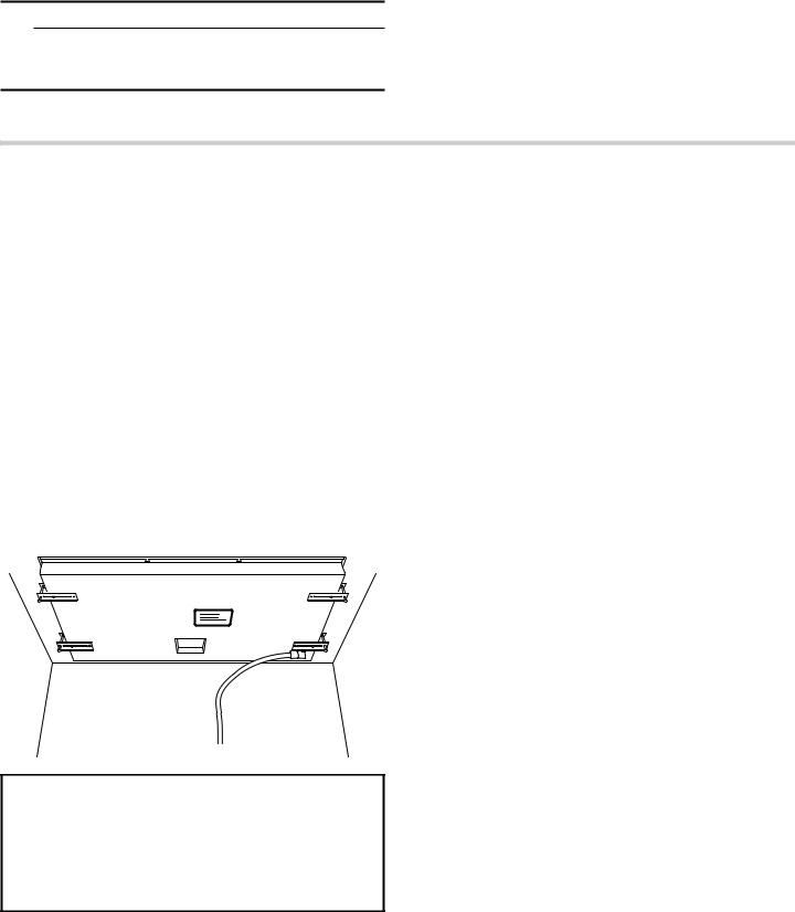
Attach flexible conduit to the junction box. Connect the lead wires to the junction box supply wires in proper phase:
black (L1) to black
red (L2) to red
green or bare to ground
|
|
|
|
|
|
|
|
|
|
1House power supply cord
2Black wire
3Junction box
4Cooktop power supply cord
5Grounded green or bare cable
6Certified UL connector
7Red wire
If the cooktop is installed and connected as specified above, it will be completely grounded in compliance with the National Electrical Code.
8
Check the Installation
9CAUTION
Before you plug in an electrical cord or turn on power supply, make sure all controls are in the OFF position.
Remove everything from the cooktop surface including stickers. Clean cooktop surface with cooktop cleaning cream.
Switch on the circuit breaker.
Verify that elements function properly.
Customer Service
Contact our Customer Service Department if your appliance needs repair. Our Customer Service Department (see below) will be happy to supply you with details on an authorized servicer near you.
E number and FD number
When you contact Customer Service, please have the Model (E) number and the FD number for your appliance available.
You can find the identification plate with these numbers:
in the appliance pass
on the underside of the appliance
You can also find the E number on the glass ceramic of your cooktop. You can check the Customer Service Index (TK) and the FD number in the basic settings. Please refer to the section on “Basis Settings” in your Use and Care manual.
Please find the contact data of all countries in the enclosed customer service list.
ZZZ ERVFK KRPH FRP
0DLQ 6WUHHW 6XLWH ,UYLQH &$
9
Loading...