


HK050-1XXX-RE
Bosch HK050-1XXX-RE, HK075-1XXX-RE, HK100-1XXX-RE, HK150-1XXX-RE, HK200-1XXX-RE Installation Instructions Manual

HK SERIES
ELECTRIC HEATER
PACKAGE
INSTALLATION INSTRUCTIONS
TABLE OF CONTENTS
Introduction .......................................................... 2
Pre-Installation ..................................................... 2
Components List ................................................... 2
Installation ............................................................ 3
Packaged Units (CE/TAxxx-xVT,
CE/TAxxx-xHZ, CE/TAxxx-xCF) ............................ 3
6 720 220 328
Revised 05-13
Split Units (CE/TAxxx-xAV,
CE/TAxxx-xAH, TAxxx-xAC) .................................. 6
CE-VT / HZ & TA-HZ (TA025-HZ excluded) Units ..... 6
Units with 5, 7.5, or 10 kW Electrical
Heater Elements (HK050, HK075, HK100) .......... 8
Units with 15 or 20 kW Electrical
Heater Elements (HK150, HK200) ....................... 8
Split Units (CE/TAxxx-xAV,
CE/TAxxx-xAH, TAxxx-xAC) ................................ 10
TA-VT & TA025-HZ Units ....................................... 10
Units with 5, 7.5, or 10 kW Electrical
Heater Elements (HK050, HK075, HK100) ........ 12
Units with 15 or 20 kW Electrical
Heater Elements (HK150, HK200) ..................... 12
Electric Heater Electrical Data ............................ 14
Field Installed Electric Heater Kit Availability ...... 14
Typical Wiring Diagrams ................................. 15-16
Introduction
2
HK Series
INTRODUCTION
Bosch HK Series Heater Package is a eld
installable electric resistance heater kit designed
for use with the CE and TA series heat pumps.
The HK series heater package requires separate
electrical service connection, independent from
the heat pump’s power supply. DO NOT wire the
heater elements into the same circuit as the
compressor.
Note:
• A heater collar is installed in the CE and TA
models, no need to order separately.
• The series heater packages are designed for
installation in the heat pump model published in
this document. Do not install this heater kit in a
heat pump not specied in this manual. Refer to
Table 3 on page 18 for compatibility.
• A heat pump thermostat with supplemental
electric heat feature is required to operate the
system when this kit is installed.
• 18 AWG wire will be needed to connect the
thermostat to the electrical box for the “W1” &
“EM” connections. See wiring diagrams at the
end of this manual.
Improper installation of the electric resistance
heater can result in severe injury or death due
to electrical shock or re.
Only trained and qualied personnel should
install, repair, or service this equipment.
All electrical service connection to the heater
must be done to National and local electrical
Standard & codes.
PRE-INSTALLATION
1. UNPACK the HK heater kit and inspect for
contents and condition. If any part or the kit
appears damaged (i.e.: broken heater elements,
damage relays) or missing, do not attempt to
install the kit. Contact your local distributor for
further help
2. Ensure that the heater kit package includes the
following components. Contact your local
distributor for further help.
COMPONENTS LIST:
The following components should be found in the
heater kit package:
a. Pre-wired heater electrical box
b. Heater elements pre-wired to the heater
electrical box
Table 1: Electric Heater Compatibilitytor Only)
Units 5kW 7.5 & 10 kW 15 kW 20 kW
TA025
TA035
TA049
TA061
TA071
CE025
CE035
CE049
CE061
CE071
ü ü
ü ü
ü ü ü ü
ü ü ü ü
ü ü ü ü
ü ü
ü ü
ü ü ü ü
ü ü ü ü
ü ü ü ü
x x
x x
x x
x x
c. Heater element(s) protective metal cover
d. Wire harness pre-wired at one end (used only in
units in which a second electrical box is added)
e. New wiring diagram
f. Adhesive back electrical data label
g. Clear hardware accessory bag containing:
• Heater element mounting screws (4 for each
element bank)
• Heater element cover mounting screws (2 for
each cover)
• Two yellow wire nuts (used only for packaged
units; discard for split systems)
• Four electrical box mounting screws (used
only in units in which a second electrical box
is added)
6 720 220 328
Subject to change without prior notice Revised 05-13
Installation
HK Series
3
h. 2 x 30 amp fuses + 2 x 60 amp fuses for 15kW
heater packages only
i. 4 x 60 amp fuses for 20kW heater packages
only
j. This installation manual
The heater element mounting screws and the
heater element cover mounting screws are the
same type of screw. Quantities used will depend
on the heater package type.
For technical assistance contact your local
distributor or Call Bosch Technical Support:
866-642-3198
3. Ensure following tools and supplies, needed
for installation, are available:
• Phillips screwdriver
• Small fl at head screwdriver
• 5/16” socket and a ratchet or drill
• Wire cutter
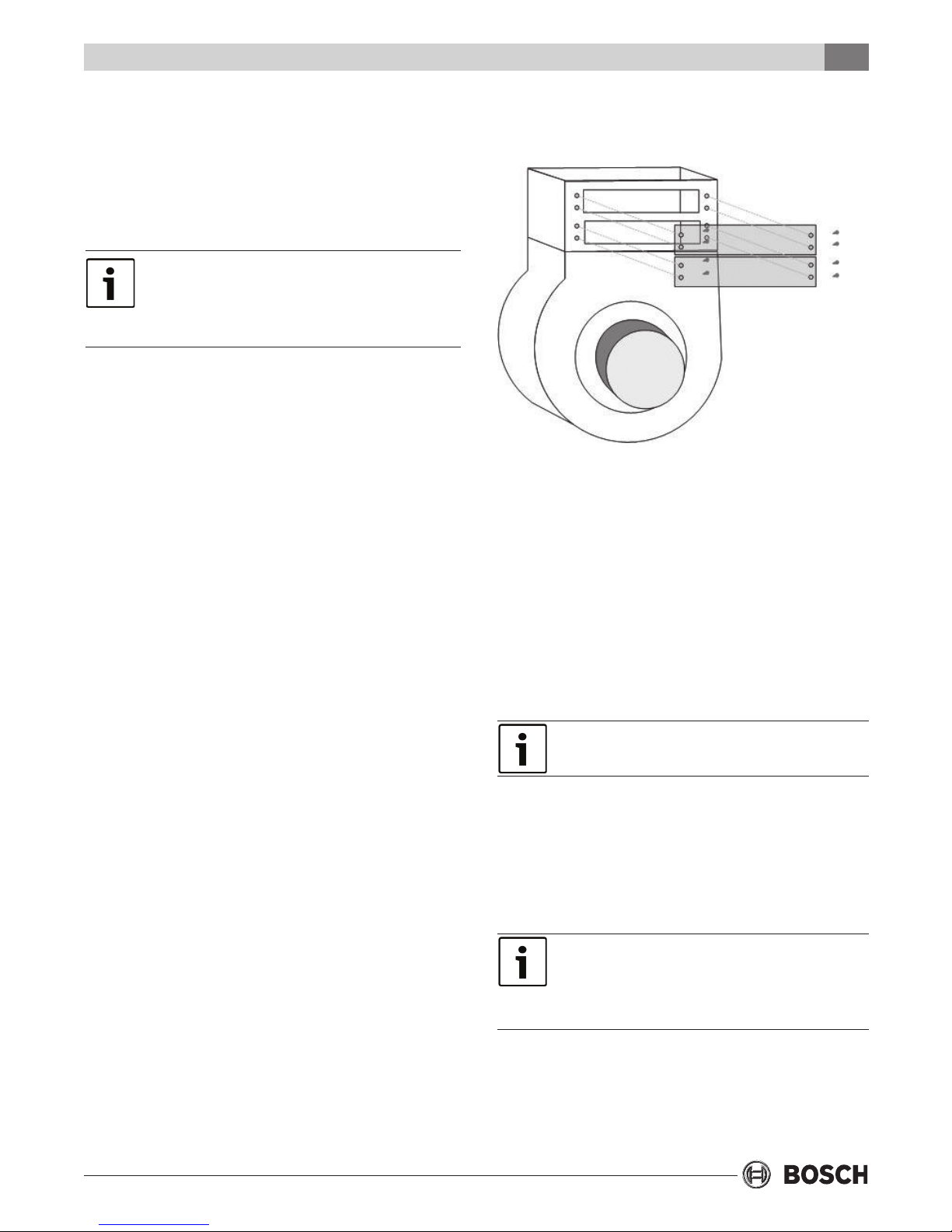
STEP 2: Remove the heater collar cover plate(s) to
install the heater elements. (See Figure 1).
Figure #1 – Showing Collar mounted on blower housing,
element location and collar plate(s)
STEP 3: Identify retainer pins on the end of the
heater element(s). These pins are to be inserted in
holes visible in the back of the heater collar. This
stabilizes the heater element and prevents
vibration of the heater elements.
• Wire stripper
• 18 AWG wire (connect thermostat to the
electrical box)
• Torque Phillips head screwdriver
• Volt meter
INSTALLATION
Packaged Units (CE/TAxxx-xVT,
CE/TAxxx-xHZ, CE/TAxxx-xCF)
This section is for packaged units only. See
sections below for installation instructions for
split systems.
STEP 1: DISCONNECTING THE POWER:
a. Turn system to “OFF” from your Thermostat
b. Turn the power to the heat pump to “OFF” at
the unit’s disconnect switch or breaker panel.
c. Remove the access panel(s) from the unit
exposing the blower section and compressor
section of the packaged heat pump unit. Place
the panel mounting screws aside in a safe
place as they will need to be reused when
putting the panels back on.
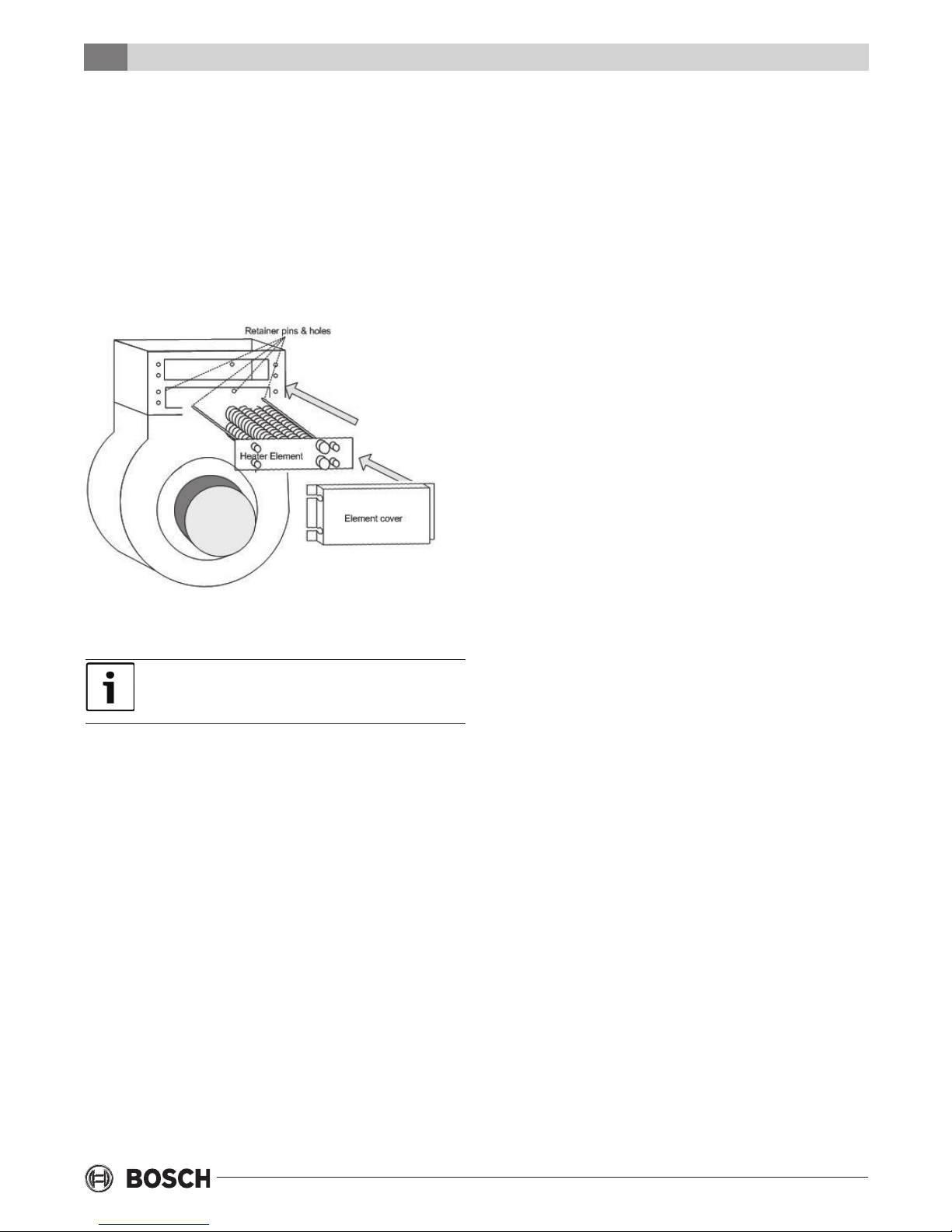
STEP 4: Slide the heater element(s) into the
mounting opening(s) on the heater collar, making
sure that the retainer pins engage in the holes in
the back of the collar.
It may be necessary to lower the blower in order
to complete this task.
When installing the heater elements into the
heater collar, ensure that the thermal overloads
are on the right side; this will be the “L1” side.
Secure each insert(s) with four of the supplied
sheet metal screws provided (See Figure 2).
It may be necessary to remove the line voltage
wires that are connected to the element(s) from
heater electrical box in order to complete
installation.
Remove the wires from heater contactor and
terminal block at “L1” only. If wires are removed
during installation, ensure that they are marked
Revised 05-13 Subject to change without prior notice
6 720 220 328
4
Installation
HK Series
for proper reconnection. When reconnecting the
line voltage wires to the contactor, apply 22 in-lbs
of torque.
STEP 5: Install the element cover over the heater
element(s). These are secured with a tab at one
end of the cover and two of the supplied sheet
metal screws at the other end (See Figure 2).
Ensure that heater wires are routed through the
plastic bushing on the heater element cover.
The mounting holes for the heater box have been
pre-punched in the posts. Make sure no wires are
pinched between the metal parts. Connect or
reconnect wires from the heater element(s) as was
marked in step 4 or follow electrical wiring diagram
for corresponding model at the end of this manual.
STEP 7: Route the loose ends of the yellow, blue,
red, purple, and the two black wire leads from the
long side of the wire harness plug from the heater
electrical box to the heat pump electrical box in the
compressor compartment. Route these wires
through the access hole in the divider panel
together where the existing blower motor wires are
routed.
STEP 8: CONNECTING HIGH VOLTAGE WIRES
a. In the heat pump electrical box, disconnect the
two line voltage wires that connect the
transformer and blower motor to the “LINE 1”
side of the compressor contactor.
b. Cut the wire terminal off of the following wires
and strip off the insulation:
Figure #2 – With Collar removed insert heater element(s) (one
shown in this diagram), wires not shown in diagram.
Ensure unused slot is covered with a collar plate.
STEP 6: INSTALLING THE HEATER CONTROL BOX:
a. Vertical Units - Install the heater control box
between the unit corner posts at the top of the
blower section.
b. Horizontal Units (Straight through
con guration) - Mount the heater electrical box
in the rear of the unit, attached to the electrical
post on the opposite side of the blower.
c. Horizontal Units (End Blow Con guration)
- Mount the heater electrical box in the rear of
the unit, attached to the electrical post on the
opposite side of the blower motor.
• One of the black wires from the wire harness
• The transformer wire disconnected in Step
8(a)
• The black blower motor wire disconnected in
Step 8(a)
c. Connect the three wires that were cut and
stripped in Step 8(b) together using a yellow
wire nut connector supplied with the kit.
Secure with electrical tape.
d. Disconnect the two line voltage wires that
connect the transformer and blower motor to
the “LINE2” side of the compressor contactor.
e. Cut the terminal connections off of the
following wires and strip off the insulation:
• The remaining black wire from the wire
harness
• The transformer wire disconnected in Step
8(d)
• The white blower motor wire disconnected in
Step 8(a)
6 720 220 328
Subject to change without prior notice Revised 05-13
Installation
HK Series
5
f. Connect the three wires that were cut and
stripped in Step 8(e) together using a yellow
wire nut connector supplied with the kit.
Secure with electrical tape.
g. Reference Figure 3 and/or the appropriate
wiring diagram at the end of the manual to
ensure that all connections are correct.
Ensure that the wires are connected to the
correct matching terminal and all unused wires
are capped with a wire nut. Severe damage to
the unit, personal injury, or death can occur if
wires are not connected securely to the
correct terminal or loose wires come into
contact with the cabinet or other components.
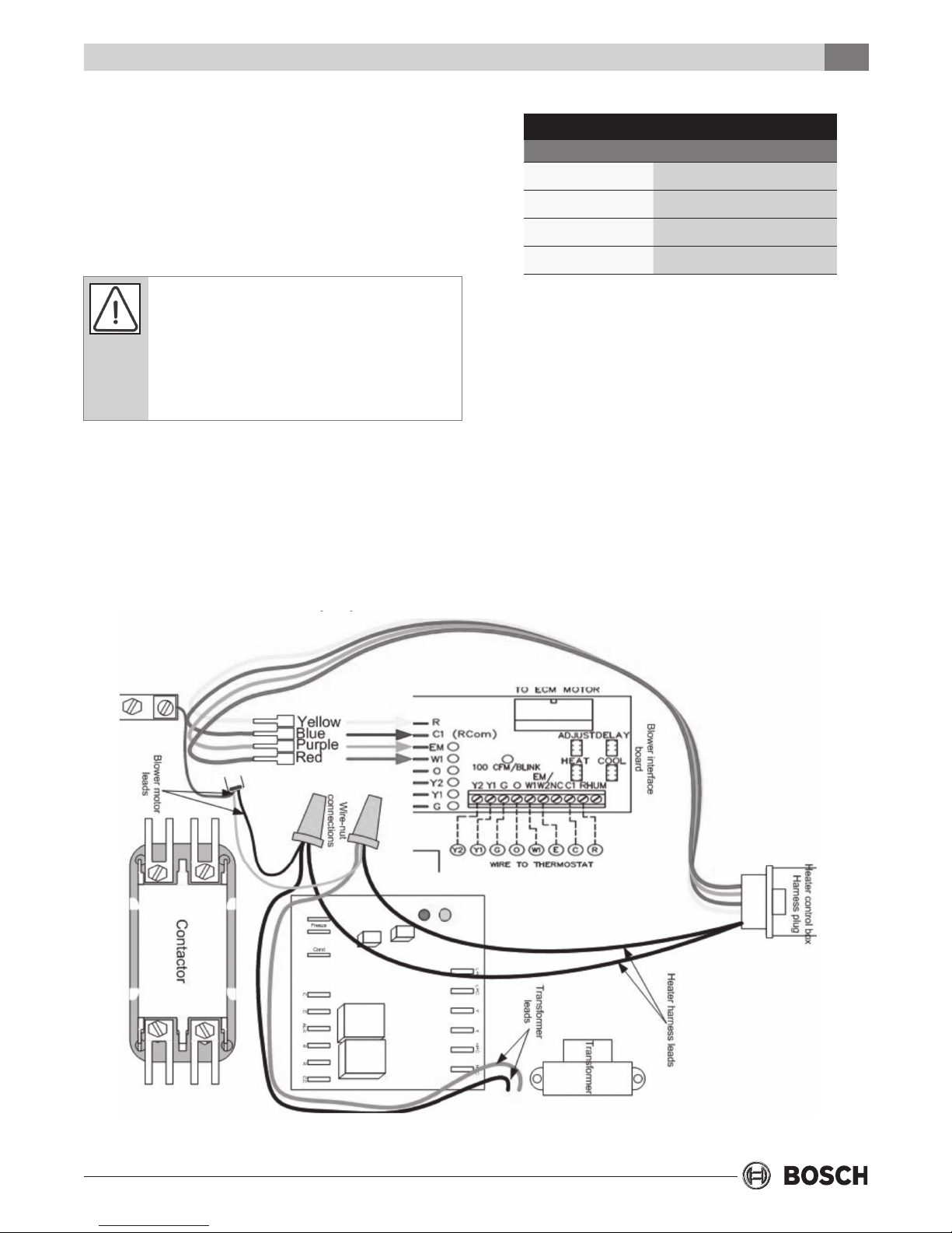
STEP 9: CONNECTING LOW VOLTAGE WIRES
a. The four remaining wires on the long end of the
wire harness are low voltage wires (Yellow,
Purple, Red, and Blue). Connect these wires to
the motor control board according to Table 2.
Table 2r Only)
Heater Box Heat Pump Box
Yellow R
Blue C1
Red W1
Purple EM
b. Reference Figure 3 and/or the appropriate
wiring diagram at the end of this manual to
ensure that all connections have been made
and are correct.
STEP 10: THERMOSTAT WIRE CONNECTIONS
a. Ensure that two low voltage wires are available
from the thermostat to make the “W1” and
“EM” connections. If these wires are not
located, they will need to be pulled and routed
from the back of the thermostat to motor
control board in the heater electrical box.
Figure #3 – Electrical Heater wiring interface with Heat Pump Electrical Box
Revised 05-13 Subject to change without prior notice
6 720 220 328
6
Installation
HK Series
b. Strip the insulation off of the “W1” and “EM”
wires and insert into the thermostat control
wire block on the motor control board. Connect
the other end of the wires to the back of the
thermostat to the supplemental and emergency
heat terminals. Reference the user’s manual for
the thermostat for proper connection.
STEP 11: ROUTING NEW LINE VOLTAGE WIRES
FROM CIRCUIT BREAKER PANEL TO HEATER
ELECTRICAL BOX
a. Select the proper wire size based upon the
heater electrical load that the blower motor and
electric heater element(s) will require. Refer to
the data tag label that is included in the heater
kit or the electrical data at the end of this
manual. Ensure that all national and local
electrical codes are followed for installation,
wire sizing, and breaker sizing.
b. Select the proper breaker size based upon the
heater electrical load that the heat pump will
require. Refer to the data tag label that is
included in the heater kit or the electrical data
at the end of this manual.
c. Route the new line voltage wiring and the
ground wire from the circuit breaker panel to
the heat pump.
STEP 13: Remove the wiring diagram that is
adhered to the back side of the front panel. Replace
with the wiring diagram that was included with the
heater kit. Using spray adhesive glue is
recommended.
STEP 14: Place the adhesive back heater data label
next to the knockout in the post where the new
electrical service for the fan motor and heater
elements is entering the cabinet.
STEP 15: RESTORING POWER / TURNING ON THE
UNIT
a. Turn the disconnect switch or breaker switch to
the “ON” position for the compressor and for
the new separate circuit servicing the blower
motor and the heating elements.
b. Test the unit in “COOLING” and “HEATING” to
ensure that full functionality of the unit has
been restored.
c. Run the unit in heating mode with the heating
elements engaged for at least 10 minutes to
ensure the unit does not shut down due to any
temperature limiting device.
STEP 16: Install the cover on the heater electrical
box and reinstall the heat pump access panel(s)
with the screws that were set aside in Step 1.
d. Use the knockout provided in the heat pump
corner post as the entry for the electrical
service wiring. A plastic bushing should be used
to protect the wire insulation from the metal
edge of the knockout.
e. Connect one of the line voltage wires to “L1”
terminal connection and the other line voltage
wire to “L2” terminal connection. Torque to 22
in-lbs.
STEP 12: Use the ground lug provided in the heater
control box to connect the eld ground from the
power supply.
The heater electrical power provides service to
the unit’s Transformer, electrical heat element(s),
and blower motor only. The Compressor remains
on the original and now isolated circuit.
Always contact your local distributor if there is
ever any doubt
SPLIT UNITS (CE/TAXXX-XAV,
CE/TAXXX-XAH, TAXXX-XAC)
This section is for CE vertical & horizontal split
units and TA horizontal (excluding the TA025) split
units only. See the section below for other split
systems or the section above relating to packaged
units.
CE-VT / HZ & TA-HZ (TA025-HZ
excluded) Units Covered in this Section
Within this range of the units, the electric heater kit
and the air handler will share a common electrical
box, therefore a single complete new electrical box
will be provided with the electrical heater kit.
6 720 220 328
Subject to change without prior notice Revised 05-13
 Loading...