


 Loading...
Repair Manual
K 1100 LT/RS
BMW AG Motorcycle Division
After Sales
Published by |
BMW AG Motorcycle Division |
|
After Sales |
|
UX-VS-2 |
All rights reserved. Not to be reprinted, translated or duplicated either wholly or in part without prior written permission.
Errors and omissions excepted; subject to technical amendment.
Produced in Germany 5/99
Introduction
This repair manual will help you to perform all the main maintenance and repair work correctly and efficiently. If it is consulted regularly by workshop personnel it will form a useful addition to the theoretical and practical knowledge acquired at the BMW Training Centre. It is a contribution towards achieving even higher Service quality.
All information in both text and illustrations refers to motorcycles in standard condition or with genuine BMW accessories installed, and not to motorcycles which have been modified in any way to depart from the manufacturer’s specification.
•The repair manual is structured in the logical sequence of the work to be performed: Removal, Disassembly, Repair, Assembly, Installation.
•The entire contents are divided into individual chapters, corresponding to the Construction Groups.
11 . 10
|
|
|
|
|
|
|
|
|
|
|
|
|
|
|
|
|
|
|
|
|
|
|
|
|
|
|
Chapter |
|
|
|
|
Page number within chapter |
|
|||||
|
|
|||||||||||
|
|
|
||||||||||
•Work to be performed during an Inspection is described in Group “00”. The various inspection routines are numbered I, II, III and IV. This numbering is repeated in the work descriptions which follow, so that work can take place without interruption.
•Use of the BMW special tools needed for certain tasks is described in the work instructions.
If the need arises, repair instructions are also issued in the form of Service Information. This information is of course incorporated into the next issue of the repair manual. We also recommend, as an additional source of information, the Electronic Parts Catalogue (ETC), which contains clear and easy-to-follow illustrations.
If the work described here is restricted to a particular equipment specification, for instance if a specific optional extra (OE) is fitted, this is stated in square brackets at the start of the item concerned, e.g. [LT].
Please refer to the following pages as well for a description of other symbols used and how to work with it.
BMW AG Motorcycle Division
After Sales
Published by: |
BMW AG Motorcycle Division |
|
After Sales |
|
UX-VS-2 |
|
D - 80788 München |
All rights reserved. Not to be reprinted, translated or duplicated either wholly or in part without prior written permission.
Errors and omissions excepted; subject to technical amendment.
Produced in Germany

Usage
Each chapter starts with the list of contents.
The list of contents is followed by the Technical Data table.
Chapter 00 “Maintenance and general instructions” details the handover checklist and lists all tightening torques and operating fluids.
Key to symbols
In this Workshop Manual for the K 1200 LT model, the following symbols are used; their meanings are explained in the table.
Special instructions aimed at improving the work procedures
L Note:
Specific information on operating, inspecting and adjusting work for the motorcycle as well as maintenance procedures.
e Caution:
Instructions and precautions specifically intended to prevent damage to the motorcycle. Failure to comply with them could invalidate the warranty.
d Caution:
This symbol stands for precautions and measures which are essential in order to protect the rider or other persons from possibly severe or fatal injury.
Contents
Headlines for the work described in the chapter........................................... |
with the relevant page number |
X Tightening torques:
Values are stated if they differ from DIN EN 24 014 or DIN 912 ISO industrial standards.

BMW AG Motorcycle Division
Maintenance Schedule |
K 75 RT/K 1100 RS/LT |
|
(from 1993 onlys) |
|
|
|
|
|
|
Customer |
Registration No. |
||
|
|
|
|
|
|
Order No. |
Signature of mechanic |
||
|
|
|
|
|
Change oil when engine at regular operating temperature, renew oil filter element 1)
BMW Inspection 1000km/600mls |
|
BMW Service 10000 km/ 6000 miles |
|
BMW Inspection 20 000 km/ 12 000 miles |
|
BMW Annual Service |
||||||||
|
|
|
|
|
|
|
|
|
|
|
|
|
|
|
|
|
|
|
|
|
|
|
|
|
|
|
|
|
|
|
|
|
|
|
|
|
|
|
|
|
|
|
|
|
Change oil in gearbox, final drive and telescopic fork 2)
Clean inductive sensor at rear wheel 2)
Grease upper/lower clutch cable nipples and side/centre stand pivots
Renew intake air cleaner element 3)
Renew fuel filter element 4)
Check hose clips on fuel and cooling system for leaks and take up slack if necessary
Check coolant level and concentration, and top up if necessary
Renew coolant after at least every 2 years *)
Check brake pads and discs for wear, renew if necessary *)
Check front/rear brake fluid level, top up if necessary *) [b SI 00 027 95 (716)]
Check brake system with regard to function, leaks; repair/renew as required *)
Renew brake fluid at least once a year
Check sensor gap for ABS at front and rear, adjust if necessary 6)
Check sensor/pulse wheel for ABS at front and rear for contamination, clean if necessary 6) 5)
Check operation of electric side stand switch (angle)
Check clutch operating clearance, adjust if necessary
Check free travel at throttle and cold-start (choke) cables, adjust if necessary
Renew spark plugs
Read out MOTRONIC fault memory 7)
Check valve clearences, adjust if necessary 8) |
|
|
|
5) |
|
|
|
|
|
|
|
|
|
|
|
|
|
|
|
|
|
|
Check steering head bearing play, adjust if necessary *)
Check battery acid level, top up with distilled water if necessary
Clean and grease the battery posts, if necessary
Take up slack at bolts and nuts:
–power unit to frame
– suspension strut mounts
–side/center stand pivot
–rear wheel studs
Apply silicone spray to guide rods of adjustable windshield (only K 1100 LT, K 75 RT)
Check idle speed, throttle synchronisation and CO value, adjust if necessary
Final inspection with safety/operating check:
–condition of tyres and wheels, tyre pressures
–lights and signal systems
–telltale and warning lights
– clutch and gear shift
–handbrake and footbrake, ABS
–steering
–instruments
–test ride, if necessary
Recommendation: In severe operating conditions, grease the throttle twistgrip and steering head bearings at least every 30,000 km (18,000 miles) *)
1)at least every 6 months; if motorcycle is used only for short journeys or at outside temperatures below 0°C, every 3 months, and at least every 3,000 km (1,800 miles)
2)at least once a year
3)in very dirty or dusty conditions, renew the intake air cleaner element every 10,000 km (6,000 miles), or even more frequently if necessary
4)normally every 40,000 km (24,000 miles), but if fuel is of poor quality every 20,000 km (12,000 miles)
5)K 75 models only
6)only motorcycles with ABS
7)only motorcycles with catalytic converter
8)on all K models, renew the lining on the chain tensioner rail every 60,000 km (36,000 miles)
*) invoiced as a separate item
Order No. 01 71 9 799 131 |
UX-VS-2, 12/98 |
Printed in Germany |

BMW AG Motorcycle Division
Pre-delivery Check |
K 75 RT/K 1100 RS/LT |
|
(from 1993 onlys) |
|
|
|
|
|
Customer |
Registration No. |
|||
|
|
|
|
|
Order No. |
Signature of mechanic |
|||
|
|
|
|
|
Inspect crates on receipt for signs of damage
Motorcycle:
–unpack
–check scope of delivery
–install front wheel
–complete
–clean
Battery:
–remove
–add battery acid
–charge
–grease the terminal posts
–re-install (mark date)
Check complete specification delivery:
–tools
–handbooks and documents
–keys
–optional extras
Check front and rear wheel brake fluid levels (only disc brake)
Check switch function of electrically-operated side stand (angle)
Check torque setting of the rear wheel retaining studs
Check tyre pressure
Fuel the motorcycle
Safety/operating check as final inspection:
–idle speed
–clutch, gear shifting
–steering
–front and rear brakes, ABS
–telltale and warning lights, instruments, lighting and signalling equipment
–adjust the headlight
–test ride, if necessary
BMW
Pre-delivery check
Order No. 01 71 9 799 131 |
UX-VS-2, 12/98 |
Printed in Germany |

Contents
Group / Chapter |
|
|
|
|
|
00 |
Maintenance and general instructions |
00.1 |
|
|
|
|
|
|
|||
11 |
Motor |
11.1 |
|
|
|
|
|
|
|||
12 |
Engine electrics |
12.1 |
|
|
|
|
|
|
|||
13 |
Fuel preparation and control |
13.1 |
|
|
|
|
|
|
|||
16 |
Fuel tank and lines |
16.1 |
|
|
|
|
|
|
|||
|
|
|
|||
|
|
|
|||
17 |
Radiator |
17.1 |
|
|
|
|
|
|
|||
18 |
Exhaust system |
18.1 |
|
|
|
|
|
|
|||
21 |
Clutch |
21.1 |
|
|
|
|
|
|
|||
23 |
Gearbox |
23.1 |
|
|
|
|
|
|
|||
31 |
Front fork |
31.1 |
|
|
|
|
|
|
|||
32 |
Steering |
32.1 |
|
|
|
|
|
|
|||
|
|
|
|||
|
|
|
|
|
|

Group / Chapter
.....................................................................................33 Rear wheel drive |
33.1 |
|
|
|
|
......................................................................................................34 Brakes |
34.1 |
|
|
|
|
.....................................................................................36 Wheels and tyres |
36.1 |
|
|
|
|
.......................................................................................................46 Frame |
46.1 |
|
|
|
|
................................................................................................51 Equipment |
51.1 |
|
|
|
|
................................................................61 General electrical equipment |
61.1 |
|
|
|
|
62 Instruments.............................................................................................. |
62.1 |
63 Lights........................................................................................................ |
63.1 |

00 Maintenance and general instructions
Contents |
Page |
Tightening torque ......................................................................................................................... |
3 |
Table of operating fluids ......................................................................................................... |
10 |
Key to maintenance intervals .............................................................................................. |
11 |
Changing engine oil .................................................................................................................. |
11 |
Inspections I, II, III, IV |
|
Changing oil in transmission (gearbox) .......................................................................... |
11 |
Inspections I, III, IV |
|
Changing oil in rear wheel drive ........................................................................................ |
12 |
Inspections I, III, IV |
|
Changing oil in telescopic fork ........................................................................................... |
12 |
Inspection I, III, IV |
|
Renewing intake air cleaner ................................................................................................ |
12 |
Inspection III |
|
Renewing fuel filter ................................................................................................................... |
13 |
Inspection III |
|
Cleaning inductive pulse generator at rear wheel drive ....................................... |
13 |
Inspections I, III, IV |
|
Checking brake pads, brake discs for wear and renewing if necessary ....14 |
|
Inspection II, III |
|
Front wheel brake |
|
Rear wheel brake |
|
Checking brake fluid level and correcting if necessary ....................................... |
15 |
Inspections I, II, III |
|
Checking brake fluid level |
|
Adding brake fluid |
|
Checking brake system .......................................................................................................... |
15 |
Inspection III |
|
Checking ABS sensor spacing and adjusting if necessary ................................ |
15 |
Inspections I, II, III |
|
Front sensor |
|
Rear sensor |
|
Renewing brake fluid ............................................................................................................... |
16 |
Renewing front brake fluid |
|
Renewing rear brake fluid |
|
00.1

Contents |
Page |
Checking function of electric switch on side stand and adjusting if necessary
Inspections I, II, III
Checking clutch clearance and adjusting if necessary ........................................ |
18 |
Inspections I, III |
|
Reading out Motronic defect code memory ............................................................... |
18 |
Inspections II, III |
|
Checking increased starting speed (choke) and adjusting if necessary ....19 |
|
Inspections I, III |
|
Checking increased starting speed |
|
Checking valve clearance and adjusting if necessary .......................................... |
20 |
Inspections I, III |
|
Adjusting valve clearance ..................................................................................................... |
20 |
Removing sprockets |
|
Removing camshafts |
|
Installing camshafts |
|
Installing sprockets |
|
Installing cylinder head cover |
|
Checking steering bearing play and adjusting if necessary .............................. |
23 |
Inspection III |
|
Lubricating guide pins, adjustable screen ................................................................... |
24 |
Inspections III, IV |
|
Checking idle speed, synchronising |
|
and CO value and adjusting if necessary ...................................................................... |
25 |
Inspections I, II, III, IV |
|
Adjusting idle speed |
|
Adjusting CO value without catalytic converter |
|
00.2
00
Tightening torque
Model |
|
|
K 1100 LT |
K 1100 RS |
|
|
|
|
|
|
|
|
|
Connection |
|
|
Nm |
|
|
|
|
|
|
|
|
|
|
11 Engine |
|
|
|
|
|
|
|
|
|
|
|
|
|
Freewheel |
|
|
|
|
|
|
|
|
|
|
|
|
|
Cover plate/freewheel cage at countershaft gear |
|
10 |
|
|
|
|
|
|
|
|
|
|
|
Oil – water pump |
|
|
|
|
|
|
|
|
|
|
|
|
|
|
|
|
|
|
|
|
Oil pressure switch |
|
|
40 |
|
|
|
|
|
|
|
|
|
|
Temperature sensor/screw plug |
|
|
9 |
|
|
|
|
|
|
|
|
|
|
Pressure relief valve |
|
|
40 |
|
|
|
|
|
|
|
|
|
|
Impeller |
|
|
33 |
|
|
|
|
|
|
|
|
|
|
Pump housing to crankcase |
|
|
10 |
|
|
|
|
|
|
|
|
|
|
Cover to pump housing |
|
|
10 (3-Bond 1209) |
|
|
|
|
|
|
|
|
|
|
Intermediate flange |
|
|
|
|
|
|
|
|
|
|
|
|
|
Thrust plate at intermediate flange |
|
|
9 (Loctite 243) |
|
|
|
|
|
|
|
|
|
|
Intermediate flange at crankcase |
|
|
9 |
|
|
|
|
|
|
|
|
|
|
Crankshaft |
|
|
|
|
|
|
|
|
|
|
|
|
|
Pinion/rotor flange at crankshaft |
|
|
50 |
|
|
|
|
|
|
|
|
|
|
Main bearing cap to crankcase |
|
|
50 |
|
|
|
|
|
|
|
|
|
|
Connecting rod |
|
|
|
|
|
|
|
|
|
|
|
|
|
Big end cap |
|
|
30 |
|
|
|
Wrench angle |
|
80 ° |
|
|
|
|
|
|
|
|
|
|
|
Input shaft |
|
|
|
|
|
|
|
|
|
|
|
|
|
Front bearing |
|
|
18 |
|
|
|
|
|
|
|
|
|
|
Rear bearing |
|
|
40 |
|
|
|
|
|
|
|
|
|
|
Engine block |
|
|
|
|
|
|
|
|
|
|
|
|
|
Crankshaft cover |
|
|
9 |
|
|
|
|
|
|
|
|
|
|
Lower part, outer |
|
|
10 |
|
|
|
|
|
|
|
|
|
|
Oil sump |
|
|
10 |
|
|
|
|
|
|
|
|
|
|
Oil filter cover |
|
|
10 |
|
|
|
|
|
|
|
|
|
|
Oil drain plug |
|
|
30 |
|
|
|
|
|
|
|
|
|
|
Cylinder head |
|
|
|
|
|
|
|
|
|
|
|
|
|
Cylinder head bolts (SI 11 062 95 (697) |
|
|
|
|
|
|
Short thread (from 6/93 to 11/94): |
|
|
22 |
|
|
|
Wrench angle, 1st stage |
64° |
|
|
|
|
|
Wrench angle, 2nd stage |
42° |
|
|
|
|
|
Long thread (since 12/94): |
|
|
20 |
|
|
|
Wrench angle, 1st stage |
75° |
|
|
|
|
|
Wrench angle, 2nd stage |
75° |
|
|
|
|
|
|
|
|
|
|
|
|
Cylinder head cover |
|
|
9 |
|
|
|
|
|
|
|
|
|
|
Camshaft |
|
|
|
|
|
|
|
|
|
|
|
|
|
Bearing cap |
|
|
9 (Apply a thin coat of 3-Bond 1209 only at cor- |
|
|
|
|
|
|
ners and butt edges) |
|
|
|
|
|
|
|
|
|
|
Chain sprockets |
|
|
54 |
|
|
|
|
|
|
|
|
|
|
00.3

|
|
Model |
|
K 1100 LT |
K 1100 RS |
|
|
|
|
|
|
|
|
Connection |
|
Nm |
|
|
|
|
|
|
|
|
|
Timing chain |
|
|
|
|
|
|
|
|
|
|
|
Chain tensioner |
|
9 |
|
|
|
|
|
|
|
|
|
Slide rail at camshaft bearing cap |
|
9 |
|
|
|
||||
|
|
|
|
|
|
|
|
Timing case cover |
|
|
|
|
|
|
|
|
|
|
|
Timing case cover |
|
10 (3-Bond 1209) |
|
|
|
|
|
|
|
|
|
Cover for Hall-effect signal transmitter |
|
9 |
|
|
|
||||
|
|
|
|
|
|
|
|
Screw plug |
|
40 |
|
|
|
|
|
|
|
|
|
Clutch |
|
|
|
|
|
|
|
|
|
|
|
Clutch housing to output shaft |
|
|
|
|
|
Tighten to |
|
140 |
|
|
|
Release and re-tighten to |
|
50 |
|
|
|
Wrench angle |
50° |
|
|
|
|
|
|
|
|
|
|
Housing cover |
|
19 |
|
|
|
|
|
|
|
|
|
Alternator |
|
|
|
|
|
|
|
|
|
|
|
Alternator to intermediate flange |
|
22 |
|
|
|
|
|
|
|
|
|
Driver |
|
33 |
|
|
|
|
|
|
|
|
|
Starter motor |
|
|
|
|
|
|
|
|
|
|
|
Starter motor to gearbox |
|
9 |
|
|
|
|
|
|
|
|
|
Mixture preparation |
|
|
|
|
|
|
|
|
|
|
|
Intake stub pipe |
|
9 |
|
|
|
|
|
|
|
|
|
Fuel injection rail |
|
9 |
|
|
|
|
|
|
|
|
|
Cooling system |
|
|
|
|
|
|
|
|
|
|
|
Coolant stub pipe at cylinder head |
|
9 |
|
|
|
|
|
|
|
|
|
Temperature sensor at coolant stub pipe |
|
30 |
|
|
|
|
|
|
|
|
|
Air cleaner |
|
|
|
|
|
|
|
|
|
|
|
Lower part of air cleaner housing |
|
21 |
|
|
|
|
|
|
|
|
|
12 Engine electrical system |
|
|
|
|
|
|
|
|
|
|
|
Starter to transmission |
|
9 |
|
|
|
|
|
|
|
|
|
Positive lead to starter |
|
5 |
|
|
|
|
|
|
|
|
|
Alternator to intermediate flange |
|
22 |
|
|
|
|
|
|
|
|
|
Clutch housing |
|
50 |
|
|
|
|
|
|
|
|
|
Base plate |
|
3,5 |
|
|
|
|
|
|
|
|
|
Setting ring |
|
2,5 |
|
|
|
|
|
|
|
|
|
Hall generator cover |
|
9 |
|
|
|
|
|
|
|
|
|
Ignition coils to intermediate flange |
|
5 |
|
|
|
|
|
|
|
|
|
Spark plug |
|
20 |
|
|
|
|
|
|
|
00.4

Model |
|
K 1100 LT |
K 1100 RS |
|
|
|
|
|
|
|
|
Connection |
|
Nm |
|
|
|
|
|
|
|
|
|
13 Fuel preparation and control |
|
|
|
|
|
|
|
|
|
|
|
Injection rail |
|
9 |
|
|
|
|
|
|
|||
|
|
|
|
|
|
Intake stub pipe |
|
9 |
|
|
|
|
|
|
|
|
|
Lower section of air cleaner housing |
|
21 |
|
|
|
|
|
|
|
|
|
Intake air line |
|
9 |
|
|
|
|
|
|
|||
|
|
|
|
|
|
Motronic control unit |
|
5 |
|
|
|
|
|
|
|
|
|
17 Radiator |
|
|
|
|
|
|
|
|
|
|
|
Connecting screw, temperature sensor |
|
9 |
|
|
|
|
|
|
|
|
|
Fastening, thermostat cover |
|
3 |
|
|
|
|
|
|
|
|
|
Radiator to frame |
|
9 |
|
|
|
|
|
|
|
|
|
Coolant stub pipe to cylinder head |
|
9 (with Loctite 243) |
|
|
|
|
|
|
|
|
|
Temperature sensor to coolant stub pipe |
|
30 |
|
|
|
|
|
|
|
|
|
18 Exhaust System |
|
|
|
|
|
|
|
|
|
|
|
Exhaust system to cylinder head |
|
21 |
|
|
|
|
|
|
|
|
|
Front silencer (muffler) |
|
12 |
|
|
|
|
|
|
|
|
|
Exhaust system holder to footrest plate |
|
33 |
|
|
|
|
|
|
|
|
|
Exhaust system to holder/footrest plate |
|
9 |
|
|
|
|
|
|
|
|
|
Retaining bracket to gearbox |
|
41 |
|
|
|
|
|
|
|
|
|
Oxygen sensor |
|
Hand-tight |
|
|
|
|
|
|
|
|
|
21 Clutch |
|
|
|
|
|
|
|
|
|
|
|
Clutch housing to output shaft |
|
|
|
|
|
tighten to |
|
140 |
|
|
|
loosen and retighten to |
|
50 |
|
|
|
tightening angle |
50° |
|
|
|
|
|
|
|
|
|
|
Housing cover |
|
19 |
|
|
|
|
|
|
|
|
|
00.5

|
|
Model |
K 1100 LT |
K 1100 RS |
|
|
|
|
|
|
|
Connection |
Nm |
|
|
|
|
|
|
|
|
23 Transmission |
|
|
|
|
|
|
|
|
|
Transmission cover to transmission |
9 |
|
|
|
|||
|
|
|
|
|
|
|
Machine screw for neutral stop |
13 |
|
|
|
|
|
|
|
|
Stud bolt, selector shaft |
17 (Loctite 243) |
|
|
|
|
|
|
|
|
Transmission to intermediate flange |
16 |
|
|
|
|||
|
|
|
|
|
|
|
Frame mounting to transmission |
45 |
|
|
|
|
|
|
|
|
Bearing mount to transmission |
41 (Loctite 243) |
|
|
|
|
|
|
|
|
Starter motor to transmission |
9 |
|
|
|
|
|
|
|
|
Positive lead to starter motor |
5 |
|
|
|
|
|
|
|
|
Fixed bearing of swinging arm to transmission |
9 |
|
|
|
|
|
|
|
|
Swinging arm bearing journal (loose bearing) |
7,5 |
|
|
|
|
|
|
|
|
Locknut of bearing journal |
41 |
|
|
|
|
|
|
|
|
Fixed bearing rear wheel drive in swinging arm |
150 (clean thread + Loctite 2701) |
|
|
|
|
|
|
|
|
Bearing pin, loose bearing rear wheel drive in swinging |
7 (clean thread + Loctite 2701) |
|
|
|
arm |
|
|
|
|
|
|
|
|
|
Locknut, loose bearing rear wheel drive in swinging |
105 (clean thread + Loctite 2701) |
|
|
|
arm |
|
|
|
|
|
|
|
|
|
Suspension strut to frame/rear wheel drive |
51 |
|
|
|
|
|
|
|
|
Brake caliper |
32 |
|
|
|
|
|
|
|
|
Hinterradschrauben |
105 |
|
|
|
|
|
|
|
|
Exhaust to cylinder head |
21 |
|
|
|
|
|
|
|
|
Silencer to holder/footrest plate |
9 |
|
|
|
|
|
|
|
|
Front silencer to transmission |
12 |
|
|
|
|
|
|
|
|
Footrest plate to transmission |
15 |
|
|
|
|
|
|
|
|
31 Front fork |
|
|
|
|
|
|
|
|
|
Oil filler plug |
10 |
|
|
|
|
|
|
|
|
Oil drain plug |
3,5 |
|
|
|
|
|
|
|
|
Spring support bearing |
20 |
|
|
|
|
|
|
|
|
Locking tube |
65 |
|
|
|
|
|
|
|
|
Hexagon nut |
65 |
|
|
|
|
|
|
|
|
Clamping screws of fork bridges |
15 |
|
|
|
|
|
|
|
|
Bottom screw fitting |
47 |
|
|
|
|
|
|
|
|
Handlebar clamp block |
22 |
|
|
|
|
|
|
|
|
Fork stabilisor |
22 |
|
|
|
|
|
|
00.6

Model |
|
K 1100 LT |
K 1100 RS |
|
|
|
|
|
|
|
|
Connection |
|
Nm |
|
|
|
|
|
|
|
|
|
32 Steering |
|
|
|
|
|
|
|
|
|
|
|
Clamping screws for handlebar fitting |
5 |
|
|
|
|
|
|
|
|||
|
|
|
|
|
|
Clamping screws |
|
22 |
|
|
|
|
|
|
|
|
|
Clamping block to fork bridge |
16 |
|
|
|
|
|
|
|
|
|
|
33 Rear wheel drive |
|
|
|
|
|
|
|
|
|
||
|
|
|
|
|
|
Threaded ring |
|
118 (clean thread + Hylomar SQ 32M) |
|
|
|
|
|
|
|
||
Hexagon nut, drive bevel gear |
200 (clean thread + Loctite 273) |
|
|
||
|
|
|
|
|
|
Housing cover |
|
35 |
|
|
|
|
|
|
|
|
|
Swinging arm fixed bearing to transmission |
9 |
|
|
|
|
|
|
|
|
||
Swinging arm bearing journal, loose bearing |
7 (clean thread + Loctite 2701) |
|
|
||
|
|
|
|
|
|
Locknut, loose bearing |
41 |
|
|
|
|
|
|
|
|
||
Fixed bearing rear wheel drive in swinging arm |
150 (clean thread + Loctite 2701) |
|
|
||
|
|
|
|
||
Bearing pin, loose bearing rear wheel drive in swinging |
7 (clean thread + Loctite 2701) |
|
|
||
arm |
|
|
|
|
|
|
|
|
|
||
Locknut, loose bearing rear wheel drive in swinging |
105 (clean thread + Loctite 2701) |
|
|
||
arm |
|
|
|
|
|
|
|
|
|
|
|
Strut to rear wheel drive |
43 |
|
|
|
|
|
|
|
|
|
|
Spring strut to frame/rear wheel drive |
51 |
|
|
|
|
|
|
|
|
|
|
Brake disc to rear wheel drive |
21 |
|
|
|
|
|
|
|
|
|
|
Brake caliper to rear wheel drive |
32 |
|
|
|
|
|
|
|
|
|
|
Wheel bolts: |
1st stage |
50 |
|
|
|
|
2nd stage |
105 |
|
|
|
|
|
|
|
|
|
Oil drain plug |
|
23 |
|
|
|
|
|
|
|
|
|
Oil filler plug |
|
23 |
|
|
|
|
|
|
|
|
|
Inductive sensor to rear wheel drive |
2,5 |
|
|
|
|
|
|
|
|
|
|
00.7

|
|
Model |
K 1100 LT |
K 1100 RS |
|
|
|
|
|
|
|
Connection |
Nm |
|
|
|
|
|
|
|
|
34 Brakes |
|
|
|
|
|
|
|
|
|
ABS pulse wheel |
4 |
|
|
|
|||
|
|
|
|
|
|
|
ABS sensor front/rear |
4 |
|
|
|
|
|
|
|
|
Brake caliperto sliding tube/rear wheel drive |
40 |
|
|
|
|
|
|
|
|
Brake line to brake caliper |
18 |
|
|
|
|||
|
|
|
|
|
|
|
Bleed screws at brake caliper front |
14 |
|
|
|
|
|
|
|
|
Bleed screws at brake caliper rear |
11 |
|
|
|
|
|
|
|
|
Brake hose to distributor |
18 |
|
|
|
|
|
|
|
|
Brake hose to master brake cylinder |
18 |
|
|
|
|
|
|
|
|
Brake disc to front wheel |
24 |
|
|
|
|
|
|
|
|
Brake disc to rear wheel drive |
21 |
|
|
|
|
|
|
|
|
Foot brake cylinder to foot rest plate |
25 |
|
|
|
|
|
|
|
|
Locknut, adjusting screw foot brake cylinder |
9 |
|
|
|
|
|
|
|
|
Distributor to fork bridge |
6 |
|
|
|
|
|
|
|
|
Brake caliperto sliding tube/rear wheel drive |
9 |
|
|
|
|
|
|
|
|
ABS unit to mounting |
9 |
|
|
|
|
|
|
|
|
Bleed screw at ABS unit |
9 |
|
|
|
|
|
|
|
|
Master brake cylinder to foot rest plate |
9 |
|
|
|
|
|
|
|
|
Mounting pin to handbrake lever |
8 |
|
|
|
|
|
|
|
|
36 Wheels and tyres |
|
|
|
|
|
|
|
|
|
Quick-release axle threaded connection |
33 |
|
|
|
|
|
|
|
|
Quick-release axle clamp screws |
14 |
|
|
|
|
|
|
|
|
Brake caliper to fork slider tube/rear wheel drive |
32 |
|
|
|
|
|
|
|
|
Wheel studs (tighten in the order stated): |
50 |
|
|
|
1. All studs handtight |
105 |
|
2.Preload the outer wheel studs in a crosswise pattern 105
3.Tighten the central stud
4.Tighten the outer studs
00.8

Model |
K 1100 LT |
K 1100 RS |
|
|
|
|
|
|
|
Connection |
Nm |
|
|
|
|
|
|
|
|
46 Frame |
|
|
|
|
|
|
|
|
|
Frame to engine |
45 |
|
|
|
|
|
|
||
|
|
|
|
|
Fairing support bracket to frame |
9 |
|
|
|
|
|
|
|
|
Suspension strut to frame/rear wheel drive |
51 |
|
|
|
|
|
|
|
|
Handlebar to clamping block |
22 |
|
|
|
|
|
|
||
|
|
|
|
|
Clamping screws of fork bridge |
15 |
|
|
|
|
|
|
|
|
Locking tube |
65 |
|
|
|
|
|
|
|
|
Hexagon nut |
65 |
|
|
|
|
|
|
|
|
Centre stand to bearing block |
41 |
|
|
|
|
|
|
|
|
Side stand to bearing block |
41 |
|
|
|
|
|
|
|
|
Footrest plate |
15 |
|
|
|
|
|
|
|
|
Brake line to handbrake cylinder |
11 |
|
|
|
|
|
|
|
|
Brake line to distributor |
11 |
|
|
|
|
|
|
|
|
51 Equipment |
|
|
|
|
|
|
|
|
|
Handlebar clamping blocks |
22 |
|
|
|
|
|
|
|
|
Shear bolts |
to shear point (~ 20 ) |
|
|
|
|
|
|
|
|
61 General electrical equipment |
|
|
|
|
|
|
|
|
|
Central earth (ground) |
9 |
|
|
|
|
|
|
|
|
Motronic control unit |
5 |
|
|
|
|
|
|
|
|
00.9

Table of operating fluids
|
|
Item |
Use |
Order number |
Quantity |
|
|
|
|
|
|
|
|
Lubricant |
|
|
|
|
|
|
|
|
|
|
|
Optimoly MP 3 |
High-performance lubricating paste |
07 55 9 062 476 |
100 g tube |
|
|
|
|
|
|
|
|
Optimoly TA |
High-temperature assembly paste |
18 21 9 062 599 |
100 g tube |
|
|
|
|
|
|
|
|
Silicone grease 300, heavy |
Damping grease |
07 58 9 058 193 |
10 g tube |
|
|
|
|
|
|
|
|
Retinax A |
Wheel, steering head and taper roller |
81 22 9 407 710 |
100 g tube |
|
|
|
bearing grease |
|
|
|
|
Contact spray |
Contact spray |
81 22 9 400 208 |
300 ml spray |
|
|
|
|
|
|
|
|
Sealants |
|
|
|
|
|
|
|
|
|
|
|
3-Bond 1209 |
Surface sealant |
07 58 9 062 376 |
30 g tube |
|
|
|
|
|
|
|
|
Loctite 574 |
Surface sealant |
81 22 9 407 301 |
50 ml tube |
|
|
|
|
|
|
|
|
Curil K 2 |
Heat-conductive sealant |
81 22 9 400 243 |
250 g can |
|
|
|
|
|
|
|
|
Hylomar SQ 32 M |
Permanently elastic sealant |
81 22 9 400 339 |
100 g tube |
|
|
|
|
|
|
|
|
Adhesives and retaining agents |
|
|
|
|
|
|
|
|
|
|
|
Loctite 648 |
Surface sealant (narrow gap) |
07 58 9 067 732 |
5 g bottle |
|
|
|
|
|
|
|
|
Loctite 638 |
Surface sealant (wide gap) |
07 58 9 056 030 |
10 ml bottle |
|
|
|
|
|
|
|
|
Loctite 243 |
Thread retainer, medium-strength |
07 58 9 056 031 |
10 ml bottle |
|
|
|
|
|
|
|
|
Loctite 270 |
Thread retainer, strong |
81 22 9 400 086 |
10 ml bottle |
|
|
|
|
|
|
|
|
Loctite 2701 |
Thread retainer, strong |
33 17 2 331 095 |
10 ml bottle |
|
|
|
|
|
|
|
|
Loctite 454 |
Cyanacrylate adhesive (gel) |
07 58 9 062 157 |
20 g tube |
|
|
|
|
|
|
|
|
3-Bond 1110 B |
Surface sealant |
07 58 9 056 998 |
5 g tube |
|
|
|
|
|
|
|
|
Cleaners |
|
|
|
|
|
|
|
|
|
|
|
Brake cleaner |
Brake cleaner |
83 11 9 407 848 |
600 ml spray |
|
|
|
|
|
|
|
|
Testing agents |
|
|
|
|
|
|
|
|
|
|
|
Penetrant MR 68 |
Crack testing agent for aluminium |
81 22 9 407 494 |
500 ml Spray |
|
|
housings |
|||
|
|
|
|
|
|
|
|
|
|
|
|
|
|
Developer MR 70 |
Crack testing agent for aluminium |
81 22 9 407 495 |
500 ml spray |
|
|
housings |
|||
|
|
|
|
|
|
|
|
|
|
|
|
00.10

Key to maintenance intervals
–Inspection at 1000 km (600 miles)I
–BMW Service at 10,000 km (6000 miles))II
–BMW Inspection at 20,000 km (12,000 miles)III
– BMW Annual Service |
IV |
Changing engine oil
Inspections I, II, III, IV
• Replace O-ring in cover, if necessary. |
|
|
|
|
X Tightening torques: |
|
|
|
|
Oil drain plug................................................ |
|
18 |
Nm |
|
Cover to oil sump........................................... |
|
6 |
Nm |
|
Quantities: |
|
|
|
|
|
|
|
|
|
Oil content ................................ |
3.50 l (6.16 |
Imp.pt) |
|
|
Oil content with filter change ....... |
3.75 l (6.6 |
Imp.pt) |
|
|
See service data for oil grades ................ |
Seite 00.3 |
|
||
|
|
|
|
|
LT000010
• [RS] Remove lower section of fairing.
11 4 650 |
|
|
1 |
 2
2
LT000020
•Change oil at operating temperature.
•Oil drain plug (1).
•Remove oil filter cover retainer (2).
•Unscrew oil filter with special wrench
BMW No. 11 4 650.
L Note:
Coat sealing ring on new oil filter element with oil. Screw in oil filter handtight, take note of hint at filter.
Changing oil in transmission (gearbox)
Inspections I, III, IV
 2
2
1 
LT000030
•Drain off oil with engine at operating temperature.
•Oil drain plug (1)
•Oil filler plug (2)
L Note:
Renew sealing rings.
X Tightening torques:
Oil drain plug................................................ |
20 Nm |
Oil filler plug ................................................. |
20 Nm |
Quantities: |
|
Oil filling capacity .................... |
0.85 l (1.496 Imp.pt) |
See service data for oil grades ................ |
Page 00.3 |
00.11

Changing oil in rear wheel drive
Inspections I, III, IV
2 
 1
1
LT000040
•Drain off oil with drive at operating temperature.
•Oil drain plug (1)
•Oil filler plug (2)
L Note:
Fill oil only up to the bottom-most thread turn of the filler hole.
Oil content: |
|
|
Initial filling ................................ |
0.25 l (0.44 |
Imp.pt) |
Oil changes............................. |
0.35 l (0.616 |
Imp.pt) |
See service data for oil grades ............... |
Page 00.3 |
|
X Tightening torques: |
|
|
Oil filler plug ................................................ |
|
23 Nm |
Oil drain plug................................................ |
|
23 Nm |
Changing oil in telescopic fork
Inspection I, III, IV
•Support motorcycle on stand.
•Unscrew oil filler plugs.
1
LT000050
• Release left and right oil drain plug (1).
•Pump out oil by compressing forks several times.
•Screw in oil filler plugs.
•Lift vehicle with lifting gear, BMW No. 00 1 510, until the front wheel can move freely.
L Note:
The load on the front wheel must be relieved to ensure as much air as possible flows in before the fixed tubes are closed off with the filler plugs so as to provide additional damping.
•Fill with specified quantity of oil.
•Close off fixed tubes.
Quantities: |
|
Oil capacity, left .................................... |
0.35 - 0.01 l |
............................................(0.616 -0.0176 Imp.pt) |
|
Oil capacity, right................................. |
0.40 – 0.01 l |
...........................................(0.704 - 0.0176 Imp.pt) |
|
See service data for oil grades................ |
Page 00.3 |
X Tightening torque: |
|
Oil filler plugs ............................................... |
20 Nm |
Renewing intake air cleaner
Inspection III
•Detach battery panel on right.
•Remove right knee pad.
•Detach right side section of fairing.
•[LT] Take off intake air pipe.
1
LT000060
•Release clips (1) at front and rear.
•Slightly raise casing cover, lift out air cleaner.
•Install in the reverse order of removal.
L Note:
Note installation position of air cleaner. Lettering at rear, arrow marking “TOP-OBEN”.
00.12
 2
2
 1
1
LT000070
Renewing fuel filter
Inspection III
•If necessary, reduce fuel level with pump until filter is clear.
•Loosen hose clip (1) and shift towards filter.
•Detach line and remove filter together with line from the fuel tank.
•Change fuel filter.
L Note:
Note direction of fuel flow on filter.
•Reconnect line to pump.
•Install in the reverse order of removal.
L Note:
Gasket (2) must not close off the overflow hole. Ensure recesses (arrows) in gasket are fitted in correct position.
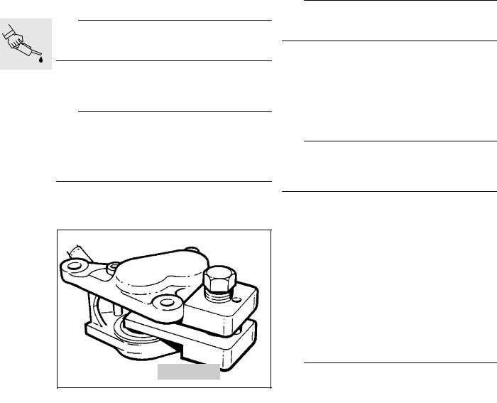
Cleaning inductive pulse generator at rear wheel drive
Inspections I, III, IV
1 
LT000080
•Release securing screw (1).
•If necessary lever out inductive pulse generator and clean with rag.
X Tightening torque:
Inductive pulse generator at rear wheel....... |
2.5 Nm |
00.13

Checking brake pads, brake discs for wear and renewing if necessary
Inspection II, III
Front wheel brake
1
LT000090
•Remove rear section of mudguard.
•Remove brake caliper.
L Note:
It is not necessary to release the brake line at the brake caliper if only the brake pads are to be changed.
•Drive out retaining pin (1).
•Remove brake pads by pulling in downward direction.
e Caution:
The brake pad thickness (arrows) must not drop below the minimum specified value.
Change pads only as complete sets.
Min. pad thickness on carrier plate....1.5 mm (0.06 in)
• Install in the reverse order of removal.
34 1 500
LT000100
L Note:
Before installing the brake caliper, completely press back pistons with resetting tool (1),
BMW No. 34 1 500.
LT000110
•Measure thickness of brake disc with a micrometer.
Wear limit .................................................... |
4.5 mm |
Rear wheel brake
1
LT000120
•Lever off cap from brake caliper.
•Remove brake caliper.
•Drive out retaining pins (1) from wheel side.
•Remove brake pads by pulling upward.
•Install in the reverse order of removal.
Mininum pad thickness on carrier plate |
....... 1.5 mm |
.................................................................. |
(0.06 in) |
Wear limit of brake disc ............................... |
4.5 mm |
................................................................ |
(0.177 in) |
00.14

Checking brake fluid level and correcting if necessary
Inspections I, II, III
Checking brake fluid level
Checking ABS sensor spacing and adjusting if necessary
Inspections I, II, III
Front sensor
Max. Max.
Min.
Min.
LT000310
L Note:
When checking front brake fluid level, the cover of the brake fluid reservoir must always be horizontal (see SI 00 027 95 (716)).
Adding brake fluid
•Take off the reservoir cover together with the diaphragm
L Note:
When adding brake fluid, note the remaining brake pad thickness. If the brake pads are new, add fluid up to the MAX mark.
•Add brake fluid.
•Replace the diaphragm and reservoir cover in position.
•Tighten the retaining screws without using undue force.
Brake fluid grade:
Use only brake fluid in quality category DOT 4 (e.g.
ATE “SL” brake fluid).
Checking brake system
Inspection III
•Check all brake lines for damage and ensure they are fitted in the correct position.
•Wipe clean all screw connections of the brake lines.
•Operate brake with force and hold for a short space of time at this point. Then inspect brake lines for any leakage points.
|
|
|
|
|
|
|
|
|
|
|
|
|
|
|
|
|
|
|
|
|
|
|
|
|
|
|
|
2 |
1 |
|
|
|
|
|
|
|
|
|
|
|
|
|
|
|
|
|
|
|
|
LT000130 |
|
|
|
|
|
|
|
|
|
|
|
|
• Check sensor spacing with feeler gauge. |
|
|||||||
Sensor spacing ............................. |
0.50 ... |
0.55 mm |
|
|||||
................................................ |
|
(0.0197... |
0.0217 in) |
|
||||
•To adjust, release sensor (1) and set spacing with spacer plates (shims) (2).
Rear sensor
|
|
|
|
|
|
|
1 |
|
|
||
|
|
|
|
|
|
|
2 |
|
|
|
|
|
|
|
|
|
LT000140 |
|
|
|
|
||
• Check sensor spacing with feeler gauge. |
|||||
Sensor spacing ............................. |
0.60 |
... 0.65 mm |
|||
................................................ |
(0.0236... |
0.0256 in) |
|||
•To adjust, release sensor (1) and set spacing with spacer plates (shims) (2).
00.15
Renewing brake fluid
Renewing front brake fluid
• Remove the break pads
e Caution:
Do not tilt the brake caliper when removing or installing, or the brake pads could be damaged.
•Take off the brake fluid reservoir cover complete with the diaphragme.
•Add brake fluid.
e Caution:
While renewing the brake fluid, its level must not drop below the MIN mark, or else air will be drawn into the brake circuit.
If this happens, the brake system will have to be bled.
•Connect a suitable vessel to the bled screws on the brake caliper to trap the escaping brake fluid, and open the bleed screw by half a turn.
34 1 500
LT000100
•Using piston resetting tool, BMW No. 34 1 500, press the pistons fully back into the brake calipers.
•Take out the piston resetting tool and insert spacer, BMW No. 34 1 520.
•Press the pistons back in the second brake caliper, but do not remove the piston resetting tool.
•Close the bleed screw.
•Apply the hadbrake lever several times until braking pressure is felt to build up.
•Hold the handbrake lever in to maintain the braking pressure and open the bleed screw, at the same time pulling the hanbrake lever up firmly.
eCaution:
Do not release the handbrake lever until the bleed screw has been closed.
•Close the bleed screw, then release the handbrake lever.
•Allow brake fluid to escape from both brake calipers in succession until it is clear and free from air bubbles.
•Close the bleed screw.
•Install the brake pads/brake calipers.
L Note:
When adding brake fluid, note the thickness of the brake pads. If the pads are new, add fluid up to the MAX mark.
•Brake fluid level = Max mark.
•Place the diaphragm and reservoir cover back in position.
•Tighten the retaining screws without using undue force.
•Make a functional check on the brakes and bleed the brake system if necessary.
Renewing rear brake fluid
•The rear brake caliper does not have to be re- mov-ed, nor its pistons forced back.
•Continue the procedure as described for front brake fluid renewal.
eCaution:
Do not release the brake pedal until the bleed screws have been closed.
00.16

a |
b |
LT000150
Checking function of electric switch on side stand and adjusting if necessary
Inspections I, II, III
•Place motorcycle on centre stand on even surface or lifting platform.
•Spray switching kinematics of the side stand with quick-action cleaner and fold in and out several times.
•Completely fold out side stand and mark position on ground surface.
•Make a second marking at distance “a” and a third marking at distance “b”.
Distances: |
|
“a”................................................... |
95 mm (3.74 in) |
“b”................................................... |
50 mm (1.97 in) |
•Fold in side stand and start engine.
•Slowly fold out side stand, the engine must stall in the area of dimension “b”.
•If the engine does not stall, the switch must be checked and replaced if necessary.
e Caution:
Bending the contact spring can result in malfunctioning of the switch.
Therefore:
Never bend the contact spring!
•Operate starter while slowly folding in the side stand; the engine must start up in area “b”.
•If the engine does not start up or if the side stand is difficult to move, check the switch or disassemble the side stand.
00.17

Checking clutch clearance and adjusting if necessary
Inspections I, III
B
1
2
LT000160
•Detach clutch cable at clutch release lever (1).
•Slightly push back rubber sleeve (2).
•With the aid of setting gauge,
BMW No. 21 3 500,set dimension “b” with adjusting screw at clutch hand lever.
Dimension “ B ” ..... 75 ± 1 mm (2.952 ± 0.03937 in)
• Reattach clutch cable at clutch release lever.
6
7
LT000170
•Using box spanner, BMW No. 21 3 610,release locknut (6) of adjusting screw (7) at clutch release lever.
•Unscrew adjusting screw by one to two turns, then screw in until pressure can be felt.
•Lock adjusting screw with locknut.
3
A 5
4
LT000180
•Set dimension “A” with adjusting screw at clutch hand lever.
•Lock adjusting screw (5) with knurled nut (3).
Dimension “A” ........ |
4 ± 0.5 mm (0.157 ± 0.0197 in) |
eCaution:
Adjust to take up wear only at the adjusting screw on the clutch release lever.
Reading out Motronic defect code memory
Inspections II, III
•Carry out this job only on motorcycles with catalytic converter.
L Note:
To read out Motronic defect code memory, see the booklet entitled:
“BMW Diagnosis, Motronic 2.1 with oxygen-sensor control” (order No. 01 70 9 798 970).
00.18

4
3
2
1
LT130030
Checking increased starting speed (choke) and adjusting if necessary
Inspections I, III
Checking increased starting speed
•Remove the left battery cover.
•Move the increased starting speed device up to its limit stop (stage 2).
eCaution:
Screw (2) is secured with lacquer and must not be reset.
L Note:
Stop face (1) must make contact with screw (2) and the wire cable must have zero play; failing this, cable play must be adjusted.
•Check stop face (1).
•Move the increased starting speed device up to its limit stop (stage 2).
•Loosen locknut (3).
•Press the lever with stop face (1) against screw
(2).
•Turn adjusting screw (4) to obtain zero play in the cable.
•Tighten locknut (3).
00.19

Checking valve clearance and adjusting if necessary
Inspections I, III
e Caution:
Never unscrew the spark plugs before measuring the valve clearance. Carbon particles may settle behind an exhaust valve head and falsify the measured result.
•[RS] Remove bottom section of fairing .
•Remove left side section of fairing.
•Remove cylinder head cover.
•Remove cover for Hall generator.
•Only crank engine at the crankshaft (counterclockwise!).
•Measure valve clearance with feeler gauge.
•Max. engine temperature 35 °C.
•Determine the replacement tappet by way of nominal/actual value comparison.
Valve clearance:
Inlet ................. |
0.15 - 0.20 mm (0.0059 - 0.0079 in) |
Exhaust ........... |
0.25 - 0.30 mm (0.0098 - 0.0118 in) |
Adjusting valve clearance
•The camshafts must be removed in order to change the bucket tappets.
•Set cylinder No. 1 (timing end) to ignition TDC.
11 3 700
LT000190
•The setting device for the camshafts,
BMW No. 11 3 700, must fit in the slots at the ends of the shafts.
•Unscrew screw plug in chain case cover.
1
11 2 640
2 3
LT000200
•Lock chain tensioner and timing chain in position with eccentric tensioner, BMW No. 11 2 640.
•Pull back clamping pin (1), screw in eccentric pin
(2) by 3-4 turns.
•Push in clamping pin above the timing chain.
•Fix timing chain and chain tensioner in position by slightly turning eccentric pin in clockwise direction.
•Secure eccentric pin with locknut (3).
Removing sprockets
1
LT000210
•Release retaining bolts of sprockets and remove sprockets.
Removing camshafts
•Remove chain guide from stud bolt.
•First remove thrust bearing of camshafts to avoid misalignment.
•Remove remaining camshaft bearings and lift out camshaft.
•Remove bucket tappets to be changed with relay pliers BMW No. 61 1 250, or a magnet.
00.20

L Note:
Only the bucket tappets replaced during the 1000 km (600 miles) inspection can be re-used.
Installing camshafts
•The camshafts are marked to ensure they cannot be confused.
eCaution:
Camshaft identification.
Inlet: Groove after the thrust bearing Exhaust: No groove
•The camshaft bearing caps are also identified. Inlet side: Odd numbers
Exhaust side: Even numbers
•The order is ascending from the front (timing end) to the rear.
•Install camshafts with the bearing points slightly oiled.
•Evenly tighten bearing cap working from the inside towards the outside.
•Install thrust bearing (timing end) last.
X Tightening torque:
Bearing cap................................................... 9 Nm
11 3 700
LT000190
•Turn camshafts so that the grooves at the rear ends are positioned vertically with respect to the cylinder head.
•The grooves at the front end must face the inside towards the crankshaft.
•Fit setting device, BMW No. 11 3 700, and secure to the bearings of the camshaft.
Installing sprockets
3
2
1
LT000210
•Install lower sprocket (1) together with chain and chain guide (2); the pin on the sprocket must engage in the groove on the camshaft.
•When installed, the marking (triangle) on the sprocket must face upward.
•Then install the upper sprocket (3) with chain.
•Initially, only tighten sprocket retaining bolts hand-tight.
e Caution:
Remove setting device before finally tightening the sprockets, otherwise the camshafts will be damaged.
•Remove eccentric tensioner.
•Firmly tighten sprockets while holding at the hexagon on the camshaft.
X Tightening torque: |
|
Sprocket to camshaft .................................. |
54 Nm |
• Check valve clearance once again.
00.21

Installing cylinder head cover
11 1990
11 1 980
LT000230
•Screw fitted bolt, BMW No. 11 1 980, (arrow) into inner hole at the front.
•Press centring pin, BMW No. 11 1 990, with gripper, BMW No. 00 5 500, into locating hole under the third camshaft bearing.
LT000240
• Insert gasket into cylinder head cover.
L Note:
Begin installation at the crescents (1).
•The marks (arrows) on the cover and gasket must agree at the front and rear.
•First press in the crescent at the rear (transmission end).
•Lightly coat the gasket groove and the crescent areas in the cover with oil to facilitate installation.
•Apply a little 3-bond 1209 in the joint area at the top and bottom chain case cover - cylinder head (surfaces free of grease).
•Fit cylinder head cover with gasket over the centring tools onto the cylinder head.
•Screw in all retaining bolts such that they are still not under preload.
•Firmly tighten retaining bolts crosswise working from the inside towards the outside.
•Remove fitted bolt and centring pin, screw in last retaining bolt and firmly tighten.
X Tightening torque:
Cylinder head cover to cylinder head ............ 9 Nm
00.22
Loading...