


Table of Contents
ON-BOARD MONITOR AND NAVIGATION SYSTEMS
Subject |
Page |
On-Board Monitor. . . . . . . . . . . . . . . . . . . . . . . . . . . . . . . . . . . . . . . . 2 On-Board Monitor System Introduction . . . . . . . . . . . . . . . . . . . . . . . . . .2 Components, Locations and Removal Information . . . . . . . . . . . . . . . . . .4 On-Board Monitor and Navigation system interfaces . . . . . . . . . . . . . . . .7 On-Board Monitor Controls and Indicators . . . . . . . . . . . . . . . . . . . . . . .8 Screen Samples of the On-Board Monitor Functions . . . . . . . . . . . . . . .11
Wide Screen Board Monitor. . . . . . . . . . . . . . . . . . . . . . . . . . . . . . . . 15
Introduction. . . . . . . . . . . . . . . . . . . . . . . . . . . . . . . . . . . . . . . . . . . . . .16
Component Overview. . . . . . . . . . . . . . . . . . . . . . . . . . . . . . . . . . . . . . .17
Principle of Operation. . . . . . . . . . . . . . . . . . . . . . . . . . . . . . . . . . . . . . .20
Workshop Hints. . . . . . . . . . . . . . . . . . . . . . . . . . . . . . . . . . . . . . . . . . .20
Mark I Navigation System. . . . . . . . . . . . . . . . . . . . . . . . . . . . . . . . . 23
Global Positioning System (GPS). . . . . . . . . . . . . . . . . . . . . . . . . . . . . .24
Navigation System Inputs. . . . . . . . . . . . . . . . . . . . . . . . . . . . . . . . . . .27
Mark I Navigation System Operation . . . . . . . . . . . . . . . . . . . . . . . . . |
.30 |
|
Mark I Navigation System Calibration Overview . . . . . . . . . . . . . . . . . . . |
35 |
|
• |
Vehicle Owner Calibration . . . . . . . . . . . . . . . . . . . . . . . . . . . . . |
35 |
• |
Dealership Calibration Procedures . . . . . . . . . . . . . . . . . . . . . . . |
38 |
Mark I Navigation System Software Loading . . . . . . . . . . . . . . . . . . . . . |
50 |
|
Mark I Diagnosis and Troubleshooting . . . . . . . . . . . . . . . . . . . . . . . . . |
51 |
|
Mark II Navigation System. . . . . . . . . . . . . . . . . . . . . . . . . . . . . . . . .53
Mark II Navigation System Introduction/ Component Locations . . . . . . .54 On-Board Monitor and Mark II Navigation System Interface . . . . . . . . . .58
Mark II Navigation Diagnosis Mode Displays . . . . . . . . . . . . . . . . . . . . .60 Mark II System Calibration . . . . . . . . . . . . . . . . . . . . . . . . . . . . . . . . . .63 Mark II System Diagnosis . . . . . . . . . . . . . . . . . . . . . . . . . . . . . . . . . . .63
Mark III Navigation System. . . . . . . . . . . . . . . . . . . . . . . . . . . . . . . . . .64
Purpose of the System. . . . . . . . . . . . . . . . . . . . . . . . . . . . . . . . . . . . . .65
System Components. . . . . . . . . . . . . . . . . . . . . . . . . . . . . . . . . . . . . . .66
Workshop Hints. . . . . . . . . . . . . . . . . . . . . . . . . . . . . . . . . . . . . . . . . . .72
Review Questions. . . . . . . . . . . . . . . . . . . . . . . . . . . . . . . . . . . . . . . . 77

ON-BOARD MONITOR SYSTEM
Model: E38, E39, E53, E46
Production Date: E46 1999 to 2002, all others 1997 to 2001.
Objectives
After completing this module you should be able to:
•Describe the controls possible from the On-Board Monitor.
•Explain the purpose of the ARCNET.
•Know how to operate the various features controlled from the On-Board Monitor.
2
On-Board Monitor and Navigation Systems
ON-BOARD MONITOR SYSTEM
The On-board Monitor System was introduced as optional equipment on the 1997 MY E38s and E39s. It was made standard on the E38 750iL for 1999 and standard for all E38s in 2000. It uses the latest advances in electronic technology to bring new levels of comfort and convenience to the driver and passengers for control of the audio/communication systems. In addition the Mark I Navigation system is incorporated into the total scope of On-board Monitor Control.
NOTE: The E39 six cylinder models with the On-board Monitor option are equipped with the high version IKE and On Board Computer functions.
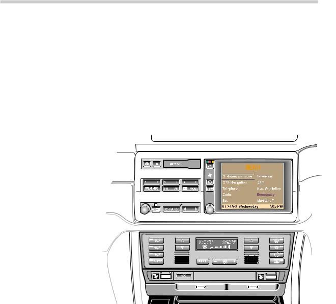
The On-board Monitor is essentially a control and display unit. All data processing and calculations are carried out by the individual system control modules. The display data is sent to the On-board Monitor over the various interfaces.
The On-board Monitor is mounted in the center dash console. It replaces the Radio/Tape Player, MID and DSP control panel (E38) if equipped.
It consists of control knobs and buttons for programming and operating the various systems.
There is a 5 1/4 inch, color LCD screen for display of all system functions. The tape player drive is also part of the On-Board Monitor unit. However, the radio receiver/amplifier module is now mounted in the trunk. The audio system is controlled from the on-board monitor. Additionally, the systems controlled and programmed through the On-board Monitor include:
•On Board Computer
•Navigation system
•Telephone
•Code Function
•Set (on-board monitor setup)
•Television (Early production only)
•Digital Sound Processor (DSP)
•Auxiliary Ventilation
•Emergency (provides vehicle location and automatically dials telephone for help).
•Monitor Off (Switches the monitor off).
3
On-Board Monitor and Navigation Systems
COMPONENTS
ON-BOARD MONITOR ASSEMBLY
The on-board monitor assembly is mounted in the center console. It consists of the following components:
Cassette tape
5 1/4 inch color LCD display screen.
•BMBT. BMBT is a German acronym meaning, “Board Monitor Bedien Tiel”. Translated to English this means On-Board Monitor Control Module/Panel. The BMBT is connected to the I-BUS. It provides the same function as the pushbutton inputs and output illumination of the LEDs of the familiar MID.
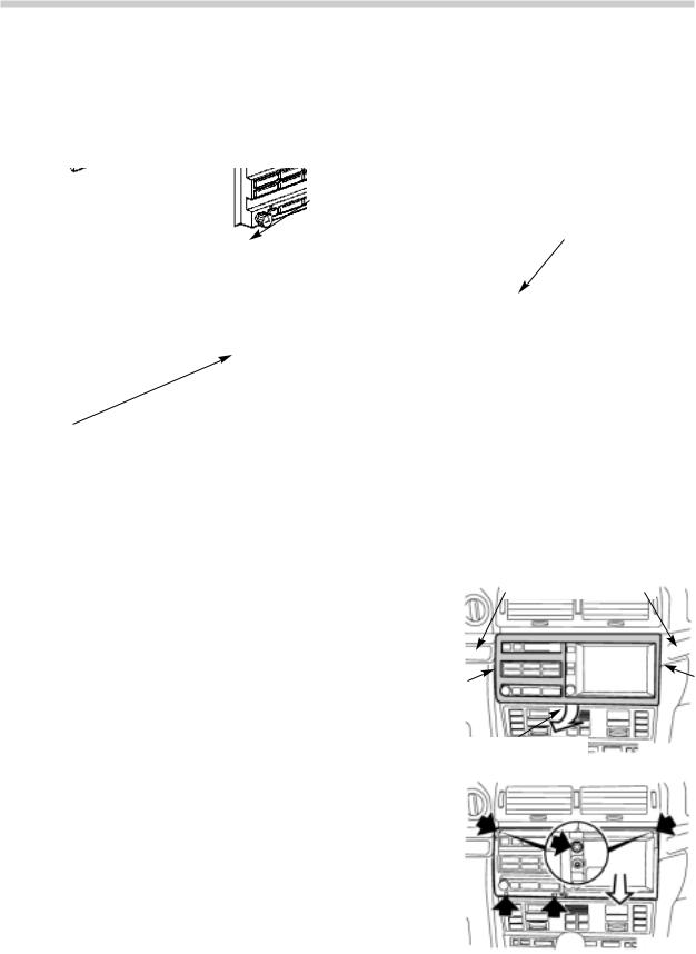
REMOVAL OF ON-BOARD MONITOR ASSEMBLY FROM CENTER CONSOLE
The on-board monitor is removed from the center console as an assembly as follows.
1.Remove the wood trim from the dash on both sides of the on-board monitor.
2.Unscrew the metal plates (E38) or unhook the latches (E39) from each side of the on-board monitor and loosen the recessed screw from the lower edge of the wood trim.
3.Remove the on-board monitor wood trim
4.With the on-board monitor wood trim removed, unscrew the four large torxTM screws as shown.
5.Pull the on-board monitor assembly out of the center console.
REMOVE WOOD TRIM
LOOSEN SCREW
For complete procedures refer to group 65 repair manual in TIS.
4
On-Board Monitor and Navigation Systems
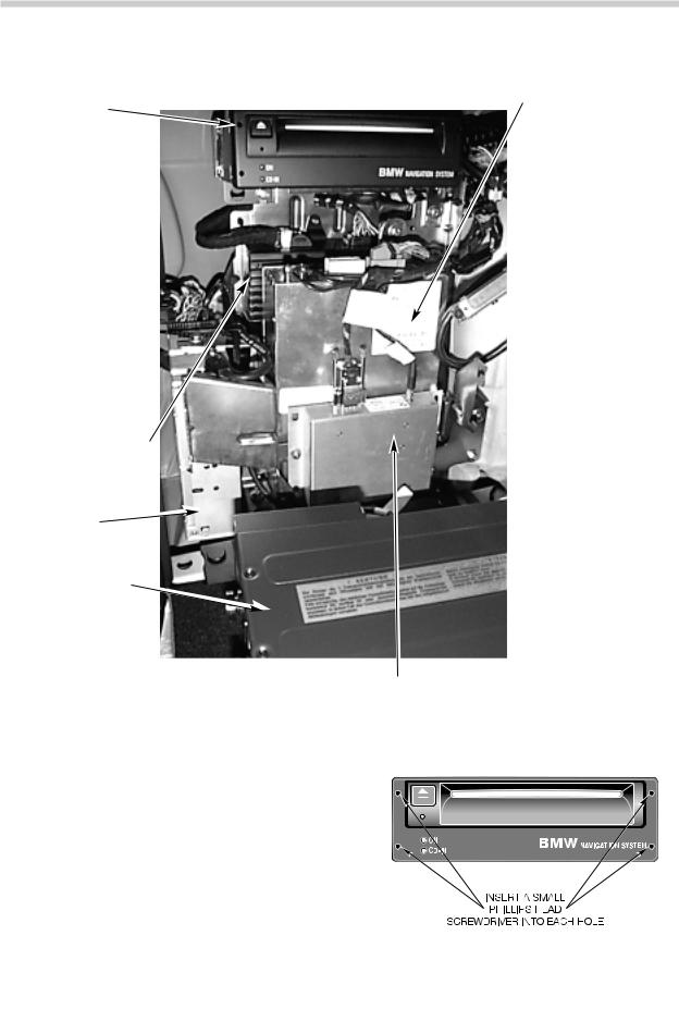
The following components are mounted in the trunk on the left side behind the trim cover
Mark I
NAVIGATION
COMPUTER
MODULE
It contains a microprocessor and CD drive for navigation system operation.
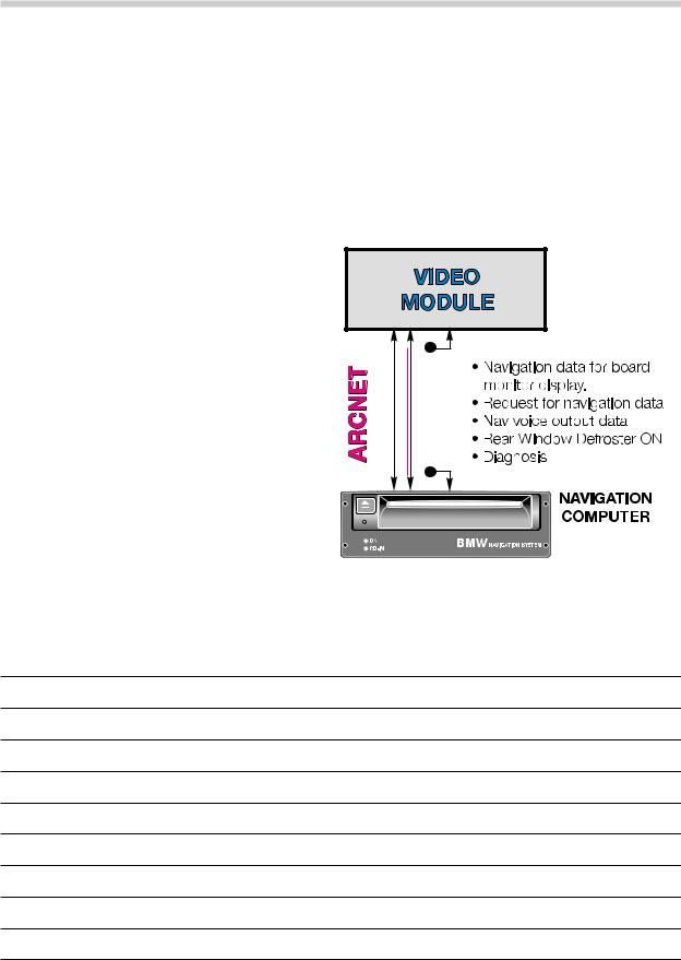
The navigation computer is linked directly to the video module which provides the visual and audio output instructions for the navigation system.
AUDIO SYSTEM
AMPLIFIER
RADIO
RECEIVER
AUDIO SYSTEM
CD CHANGER
GLOBAL POSITIONING RECEIVER MODULE (GPS)
VIDEO MODULE
The video module generates the Red, Green and Blue video signals for the on-board monitor LCD screen. The RGB signals are for all functions of the on-board monitor including the nav. system.
The video module also serves as a data memory for the navigation system. As needed the video module instantly provides the RGB signals to change the onboard monitors display and sends the audio signals to the audio system amplifier.
The module determines the exact position of the vehicle from known orbits of GPS satellites. The GPS receiver interfaces with the Navigation computer module for determining the vehicle position.
NAVIGATION COMPUTER REMOVAL:
To remove the nav. computer from the mounting bracket insert four small phillips head screwdrivers into the four holes on the face
plate. Push the screwdrivers in past a slight
detent. Pull the nav. computer out of the mounting bracket.
5
On-Board Monitor and Navigation Systems
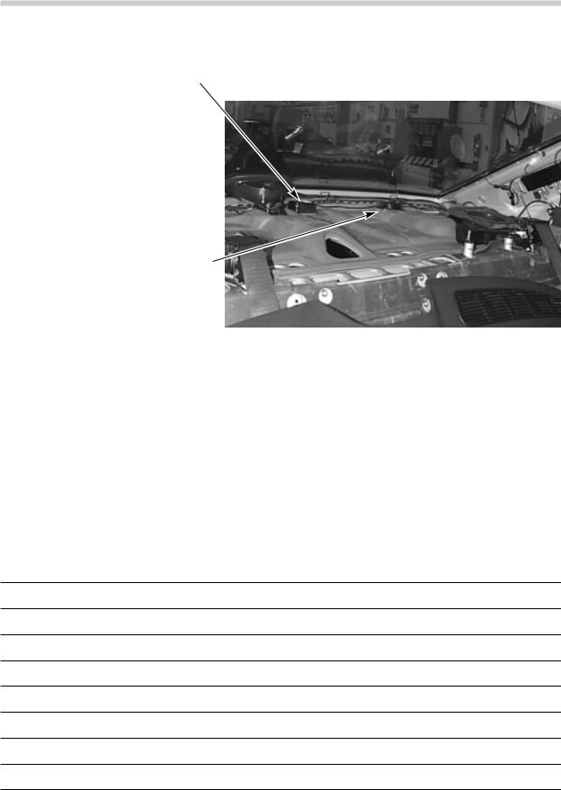
The following components are located on the rear parcel shelf under the trim panel.
MAGNETIC FIELD SENSOR
The magnetic field sensor is a small micro processor. It is used while the navigation system is operating to determine the vehicle’s direction of travel.
GLOBAL POSITIONING
RECEIVER ANTENNA
The antenna picks up the signals from the satellites and transmits them to the GPS module.
Carry over components that are part of the On-Board Monitor / Navigation system include:
•Instrument Cluster Control Module (IKE) for On Board Computer calculations
•Multi-Function Steering Wheel (MFL) for radio and telephone control functions.
•Telephone handset for operation of the phone.
•ASC control module for the two front wheel speed sensor inputs.
6
On-Board Monitor and Navigation Systems
ON-BOARD MONITOR AND NAVIGATION SYSTEM INTERFACES
I BUS - The On-board Monitor Control Module/Panel is connected to the I-Bus for communication with the other I-Bus components. Data communication takes place over the I-Bus between the BMBT and the following modules:
• |
IKE |
• |
Radio Receiver |
• |
Telephone Handset |
• |
Video Module |
• Multi-Function Steering Wheel (MFL) |
• |
Audio System Amplifier |
|
ARCNET - The Attached Resource Computing Network is a high speed (2 MB/sec) digital data link. The Navigation Computer and Video Module are connected by the ARCNET for isolated high speed navigation system communication.
The ARCNET is made up of two data wires and a shield similar to the familiar CAN data link. The shielded ARCNET cable has its own triaxial type connector ends that are pushed onto their mating connectors on the modules.
Video Module Red, Green Blue (RGB) output - The On Board Monitor is connected to the Video module through the RGB connection for the LCD screen displays. Each of the three color signals is shielded.
7
On-Board Monitor and Navigation Systems
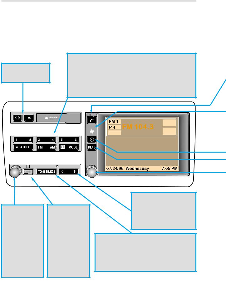
ON-BOARD MONITOR CONTROLS & INDICATORS
AUDIO SYSTEM
Operation of the audio system (radio/tape/CD) is similar to current systems installed in other models. The major difference is that the display of stations and settings is through the LCD panel.
Tape program and eject buttons.
1-6 buttons correspond to stored radio stations (12+6 Auto) and CD selections (CD 1-6 selection).
Weather Band, FM - AM, Dolby and Mode Selection.
Mode = Radio, Tape or CD function.
|
|
|
|
|
|
|
|
|
|
|
|
|
|
|
|
|
|
|
|
|
|
|
|
|
|
|
|
|
|
|
|
|
|
|
|
|
|
|
|
|
|
|
|
|
|
|
|
|
|
|
|
|
|
|
|
|
|
|
|
|
|
|
|
|
|
|
|
|
|
|
|
|
|
|
|
|
|
|
|
|
|
|
|
|
|
|
|
|
|
|
|
|
|
|
|
|
|
|
|
|
|
|
|
|
|
|
|
|
|
|
|
|
|
|
|
|
|
|
|
|
|
|
|
|
|
|
|
|
|
|
|
|
|
|
|
|
|
|
|
|
|
|
|
|
|
|
|
|
|
|
|
|
|
|
|
|
|
|
|
|
|
|
|
|
|
|
|
|
|
|
|
|
|
|
|
|
|
|
|
|
|
|
|
|
|
|
|
|
|
|
|
|
|
|
|
|
|
Switches the |
Toggles the |
|
|
|
|
|
|||||||||||
audio system |
audio display in |
|
|
|
|
|
|||||||||||
on/off (PUSH) |
the monitor |
|
|
|
|
|
|||||||||||
and adjusts the |
back to the |
|
|
|
|
|
|||||||||||
volume |
previous |
|
|
|
|
|
|||||||||||
(ROTATE). |
screen. |
|
|
|
|
|
|||||||||||
Both the radio |
Amber LED |
|
|
|
|
|
|||||||||||
and the |
illuminated |
|
|
|
|
|
|||||||||||
monitor display |
when radio is |
|
|
|
|
|
|||||||||||
are switched |
on. |
|
|
|
|
|
|||||||||||
8
Arrow rocker switch. Adjusts the tone settings and is used for the seek/scan function for the radio, tape and CD track.
TONE-SELECT
Tone: Adjusts the bass, treble, balance and fader using the tone & arrow buttons. Select: provides choice of station selection method, ie: Manual, Scan, Scan Sensitivity.
On-Board Monitor and Navigation Systems
TELEPHONE BUTTON AND INDICATORS
Send/End button. As on previous systems this button sends the call to the displayed telephone number in the On-Board Monitor display or ends the current call.
The telephone LEDs correspond to the E38/E39 MID: Green = Phone call in progress
Red = Phone is on
Amber = Steady: Roaming in same type system as home system Flashing: Roaming in different type system as home system
Fan Symbol: Flashing indicates the park car ventilation system is programmed for activation. Steady indicates the parked car ventilation is currently on.
Clock Button: Displays the time with the key switched OFF. Additionally, this button also switches the parked car ventilation system to off when it is on.
ON SCREEN CONTROLS
There are two main controls for all of the monitor screen displays.
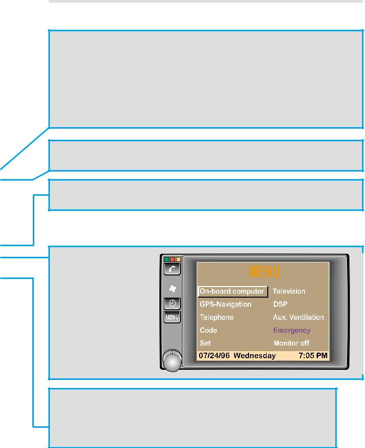
MENU BUTTON
The menu button is used to call up the Main Menu as shown at right.
This Menu provides access to all of the OnBoard Monitor functions including:
ROTARY KNOB
PUSH = Switches the monitor on or activates the selected program displayed in the monitor.
ROTATE = Selects the desired function for programming or display
9
On-Board Monitor and Navigation Systems

CHECK |
ENGINE |
ABS/ASC
10
On-Board Monitor and Navigation Systems
SCREEN SAMPLES OF THE ON-BOARD MONITOR FUNCTIONS
ON BOARD COMPUTER
The functions of the On Board Computer remain the same as previous systems. All On Board Computer calculations are still performed by the IKE.
The OBC is called up from the Onboard Monitor main menu by highlighting the BC and pressing the knob.
Once the computer functions are displayed, all programming and resetting of the displays is carried out using the rotary knob.
MARK I GPS NAVIGATION
The on-board monitor provides access to the new Navigation system.
The Mark I Navigation system is controlled and displayed via the onboard monitor.
11
On-Board Monitor and Navigation Systems

TELEPHONE
Selecting the Telephone function on the Monitor screen will call up a rotary dial display. The telephone can be dialed with the rotary knob by turning the knob and pressing it when the desired digit is highlighted. Once the number is input, the call is initiated by pressing the send/end button at the left of the Monitor.
All telephone programming is carried out through the handset as on other telephone models.
Other features of the monitor telephone control include:
•Memory storage and recall
•Information on signal strength and call timer
•Top 8 number storage
•Emergency call feature
-Displays 911 or Assist.
-Displays the vehicles current coordinates in latitude and longitude along with the street name (if the street is on the digitized map database).
CODE FUNCTION
The familiar BC code function is carried over to the On-board Monitor system. A four digit code can be entered into the system that will disable the vehicle from starting as with previous systems.
12
On-Board Monitor and Navigation Systems
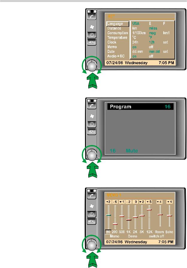
SET (On-Board Monitor Setup
Utility)
The Set Menu provides the on-board monitor display set up. This includes:
•Language Selection
•Time/date set and format
•Etc.
The “Audio+BC” selection at the bottom of the list switches the BC display off when the audio display is in the monitor.
TELEVISION
Early production only! The television function will be selectable from the main menu. Though audio is heard, television images will not display in the On-board Monitor.
E38: vehicles are prewired for television viewing in the rear seat. A TV monitor connector is located in the rear of the center console for this purpose. This is only possible with owner purchased equipment. The On-board monitor will only serve as the controller for rear seat television.
DIGITAL SOUND PROCESSOR (DSP)
The DSP system, introduced with the E38 is controlled and programmed through the On-board Monitor.
NOTE: US Law prohibits television display in the front seat viewing area.
13
On-Board Monitor and Navigation Systems
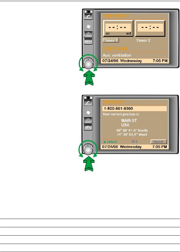
AUXILIARY VENTILATION
The control and programming of the auxiliary ventilation feature is done with the on-board monitor. Use the rotary knob to program the on times for system operation.
EMERGENCY
The Emergency function provides the exact location of the vehicle including:
• Street and Town (if on digitized map)
• Longitude and Latitude Coordinates
If the vehicle is equipped with a telephone, 911 or Assist (BMW roadside assistance) can be called directly from this screen.
If the vehicle is not equipped with a phone the emergency program provides your location.
MONITOR OFF
Pressing the “Monitor Off” button switches the monitor to a blank screen. All programs are still functioning but not displayed in the monitor. The monitor is turned back on by pressing or turning any button on the on-board monitor.
14
On-Board Monitor and Navigation Systems

WIDE SCREEN ON-BOARD MONITOR
Model: E39,E38,E46,E53
Production Date: E38,E39 from 9/00 E53 from 1/01
E46 Cabrio from 3/01
all other E46 models from 9/01
Objectives
After completing this module you should be able to:
•Describe the benefits of the wide screen monitor over the previous versions.
•Understand how to operate the wide screen monitor.
•Review the procedures to access the Service Modes.
15
On-Board Monitor and Navigation Systems

Introduction
While the instrument cluster provides all of the important vehicle status information to the driver, the on-board monitor is designed as an additional display that can be viewed by both the driver and vehicle passengers. Information relating to the vehicle, navigation, audio system and telephone can be displayed and controlled from a central location.
The wide screen on-board monitor replaces both the 5.5’’ versions in the E38 and E39, and the 5’’ board monitor from the E53 and E46. The wide screen display has a screen size of 6.5’’ and an aspect ratio (length:height) of 16:9.
The benefits of the wide screen design are:
•Larger display area and higher resolution (400X234 pixels).
•Improved display screen technology (Ad-TFT LC).
•Bigger text size.
•Soft keys replace country specific audio function keys.
•Used for all board monitor applications in all markets reducing variants.
•Larger display area makes split screen and magnification features possible (future software enhancements).
16
On-Board Monitor and Navigation Systems
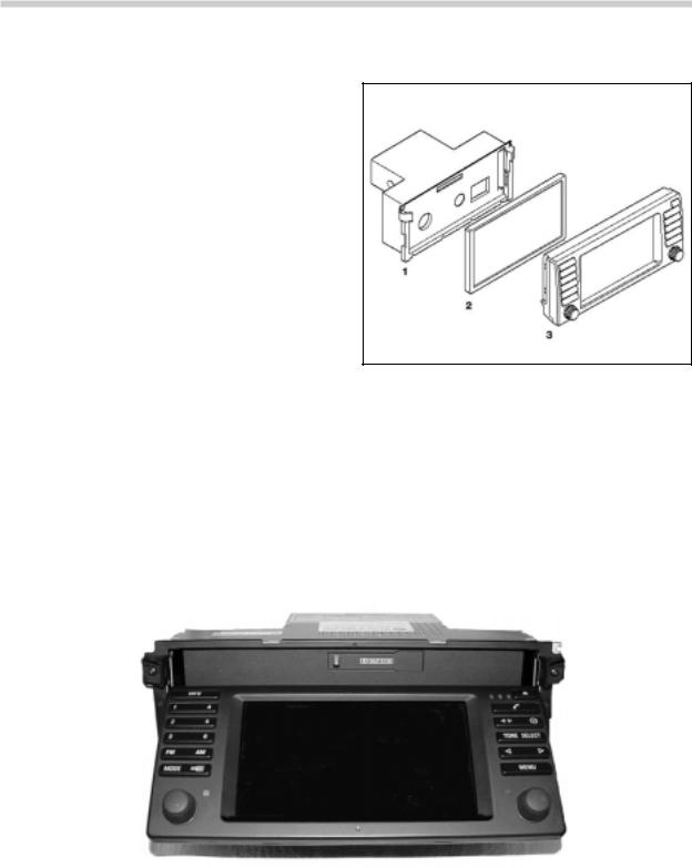
Component Overview
The wide screen on-board monitor consists of:
1.Monitor housing with cassette drive
2.Display screen
3.On-board monitor control panel
Cassette Drive
The cassette drive is located behind the on-board monitor screen. In order to access the cassette, press the “eject” button, the display screen tilts forward to uncover the cassette slot. The images will remain displayed on the screen.
After pressing the “eject” button again or automatically after 15 seconds the display returns to its normal position (cassette must be completely inside or removed). The tilt mechanism for the display screen utilizes anti-trap, if the board monitor detects a sudden change in speed, the display will reverse direction.
17
On-Board Monitor and Navigation Systems
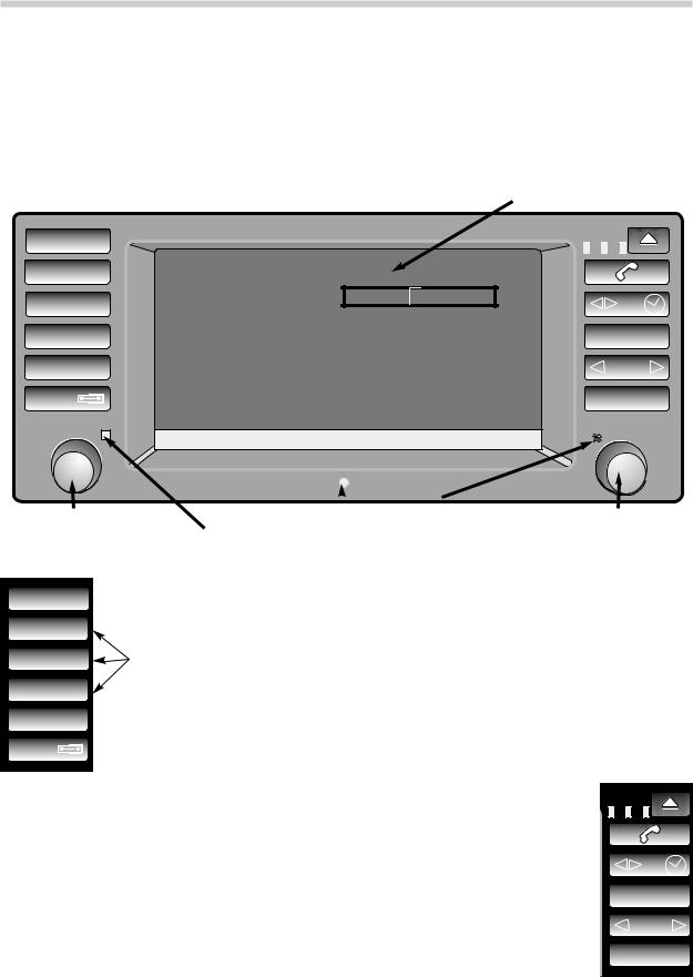
Display Screen and Control Panel
The display screen has a diagonal width of 6.5’’ and an aspect ratio of 16:9 compared to the previous monitors that had a ratio of 4:3. The new screen also uses a Ad-TFT display (Advanced Thin Film Transistor). This type of screen uses ambient light in addition to backlighting in order to illuminate the display. The advantage is a constant contrast and brightness level at all ambient lighting conditions.
INFO |
|
|
|
|
1 |
4 |
|
MENU |
|
2 |
5 |
On-board computer |
GPS-Navigation |
|
|
|
|
||
3 |
6 |
DSP |
Aux. Ventilation |
TONE SELECT |
|
|
|||
FM |
AM |
Code |
|
|
|
|
|
||
|
|
|
Emergency |
|
MODE |
|
Set |
Monitor off |
MENU |
11.13.2000 Thursday
RADIO CONTROL KNOB |
PHOTOCELL |
|
SENSOR |
ON-BOARD MONITOR CONTROL |
|
|
|||||
RADIO STATUS LED = Signal from |
|
|
|
KNOB |
|
radio via I/K bus. |
|
AUXILIARY FAN INDICATOR LED |
|||
INFO INFO = Activates the soft key menu for RDS and PTY
14
2 |
5 |
1-6 BUTTONS = Audio presets and CD selection |
3 |
6 |
FM |
AM AM/FM SELECTION |
MODE |
MODE/DISPLAY = Mode selects between audio functions. Display alternates between |
|
radio display and other displays. BC,TEL,NAV etc. |
TELEPHONE STATUS LEDs / EJECT = Tilts monitor to access cassette drive.
TELEPHONE = Send/End button |
|
TAPE REVERSE/CLOCK = Clock: Pressing with key off displays time. Aux. ventilation |
|
can be switched by holding button longer. |
|
TONE/SELECT=Tone: Dolby (cassette only) and audio adjustments. |
TONE SELECT |
Select: Choose between station search methods (a,m or scan). |
|
FAST FORWARD/REVERSE / STATION SEARCH |
|
MENU = Returns display to main menu |
MENU |
|
18
On-Board Monitor and Navigation Systems
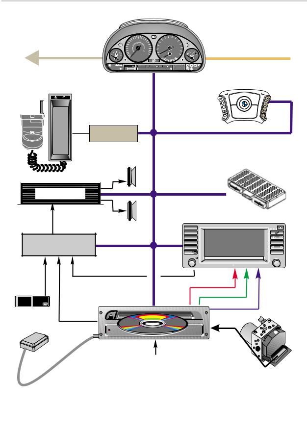
Wide Screen Board Monitor Interface
K-BUS
|
|
|
80 |
|
3 |
4 |
|
|
|
|
60 |
100 |
2 |
|
1/min |
5 |
|
||
|
120 140 |
|
|
x 1000 |
|
||||
|
|
100 |
160 |
|
|
|
|
|
|
|
40 |
80 |
180 |
120 |
|
|
|
|
|
0 |
60 |
200 |
0 |
|
|
7 |
DIAGNOSIS BUS |
||
20 |
40 |
km/h |
140 |
|
|
||||
|
|
|
220 |
|
|
|
|
6 |
|
½ |
|
20 |
240 |
|
|
|
|
|
|
|
|
|
MPH |
|
40 |
20 |
|
0 |
|
|
|
ELECTRONIC |
|
|
15 10 |
|
|
||
|
|
|
|
! |
|
|
|
|
|
|
|
|
123456 miles122 4 |
+72 0F |
PRND SM |
P ! ABS |
|||
CHECK |
OIL SERVICE |
20 |
DIGIT READOUT |
|
54321 |
|
|||
ENGINE |
INSPECTION |
|
|
||||||
B |
M |
W |
|
StarTAC |
Telephone
PSE Box
SRS
AIRBAG
BMW
MFL-CM
|
|
I-BUS |
|
|
|
|
|
|
LCM III |
|
|
AMPLIFIER |
|
|
|
|
|
AUDIO SIGNALS |
|
|
|
|
|
FOR AMPLIFICATION |
INFO |
|
|
||
|
|
|
|
||
|
|
1 |
4 |
|
|
|
|
2 |
5 |
|
|
BM53 |
|
3 |
6 |
|
|
|
FM |
AM |
|
|
|
|
|
MODE |
|
|
|
|
|
|
|
13.07.2000 Thursday |
10:17 |
CD |
TAPE PLAYER |
|
|
|
|
AUDIO SIGNALS |
|
|
|
|
|
PLAYER |
|
|
|
|
|
|
|
|
|
|
|
AUDIO |
|
|
RED SIGNAL |
|
|
SIGNALS |
|
|
|
GREEN SIGNAL |
|
|
|
|
|
|
|
NAVIGATION |
|
|
|
BLUE SIGNAL |
|
AUDIO |
|
|
|
||
|
|
|
|
|
|
SIGNALS |
|
|
|
|
|
GPS |
|
|
|
|
|
ANTENNA |
POWER |
GPS NAVIGATION SYSTEM |
|
|
|
|
|
|
|
||
|
|
|
|
DSC |
|
|
|
|
|
(processed |
|
|
REVERSE SIGNAL FROM |
left front wheel |
|||
|
LCM |
|
|
speed signal) |
|
|
|
|
|
|
|
TONE SELECT
MENU
CH
BOS
Example of E38/E39 with Wide Screen Board Monitor
19
On-Board Monitor and Navigation Systems

Principle of Operation
The on-board monitor is an input and display device that performs no internal calculations.
Inputs from the control panel buttons and knobs are converted into I-bus (K-bus E46) signals by the BM control panel. All of the devices controlled by the BM are connected to the I/K bus interface.
The navigation computer contains the graphics stage integrated into the navigation computer housing. Request for on-board monitor displays are made to the navigation computer via the I/K bus. The navigation computer generates the RGB video signals and transmits them via 3 shielded wires.
Audio signals generated by the cassette drive are sent via traditional audio wires (4) to the radio (located in the trunk or cargo area) for output to the audio system amplifier.
Workshop Hints
Service mode
Access for the radio, on-board monitor and navigation service modes is available through the on-board monitor screen.
To enter the radio service mode:
•Turn the ignition key to position 1 (KLR).
•Turn the radio on, then off, then on again.
•Press the “INFO” button. From the selection list choose “RDS”.
•Press and hold the on-board monitor control knob for at least 8 seconds.
•The audio display window will show the radio serial number as the first display.
•The station search < > buttons are used to scroll through the various settings.
•Turn off the radio to “set” any changes made.
1
INFO |
|
|
|
1 |
4 |
INFO |
|
|
|
PTY |
2 |
2 |
5 |
RDS |
|
3 |
6 |
|
TONE SELECT |
FM |
AM |
|
|
MODE |
|
|
MENU |
Note: See the “NG” Radios module for a list of the tests and settings available in the radio service mode.
11.13.2000 Thursday |
10:17 |
3
20
On-Board Monitor and Navigation Systems
To enter the On-Board Monitor and Navigation Service Mode:
•Turn the ignition key to position 1 (KL R).
•From the Menu screen select “SET”.
•Once in the Set screen, press and hold the “MENU” button for 8 seconds.
•The Service Mode menu will appear on the display.
•Select “On-board monitor” for monitor specific tests.
INFO |
|
|
|
|
|
INFO |
|
|
||
1 |
4 |
SET |
|
SW 3-1/20 |
|
1 |
4 |
SERVICE MODE |
|
|
|
|
|
|
|
|
|||||
2 |
5 |
Language |
USA |
E |
|
|
|
|
On-board monitor |
|
Distance |
km |
miles |
|
|
2 |
5 |
|
|||
|
|
|
|
|||||||
|
|
|
|
|
|
NAVIGATION/GRAPHIC ELEMENT |
|
|||
|
|
Consumpt. |
1/100km |
mpg |
km/l |
|
|
|
|
|
3 |
6 |
TONE SELECT |
3 |
6 |
|
TONE SELECT |
||||
Temp. |
C |
F |
|
Video Module |
||||||
|
|
|
|
|
|
|
||||
FM |
AM |
Clock |
24h |
12h |
set |
|
FM |
AM |
GPS |
|
|
Sensor check |
|
||||||||
|
|
|
|
|
|
|
|
|
|
|
MODE |
|
|
dd.mm |
mm/dd |
set |
MENU |
|
|
Telematics |
|
|
Date |
MODE |
|
|
MENU |
|||||
|
|
|
|
|||||||
|
|
Audio+OBC |
on |
off |
|
|
|
|
|
|
|
|
11.13.2000 Thursday |
|
10:17 |
|
|
|
11.13.2000 Thursday |
10:17 |
|
Press and hold for 8 seconds after entering |
Service Mode main menu display |
||||
the “SET” screen. |
|
|
|
||
INFO |
|
|
|
||
1 |
4 |
ON-BOARD MONITOR VERSION |
|
|
|
|
|
|
|||
2 |
5 |
Sw level |
return |
|
|
Hw level: |
Version |
|
|||
|
|
|
|||
3 |
6 |
Diag. Index: |
Key function |
TONE SELECT |
|
Bus index: |
Brightness |
||||
|
|
|
|||
FM |
AM |
Encoding index: |
|
|
|
|
|
Supplier |
|
|
|
MODE |
|
|
|
MENU |
|
|
|
Return |
Functions |
|
|
|
|
|
|
||
|
|
11.13.2000 Thursday |
10:17 |
|
|
Tests and adjustments available for the on-board monitor are:
•Version Information
•Key Function (button and rotary knob test)
•Brightness (Screen brightness adjustment)
21
On-Board Monitor and Navigation Systems

Diagnosis
Fault driven diagnosis is possible using the DIS/MoDiC Diagnosis Program. The Diagnosis Program features:
• Identification
•Read/Clear fault memory
•Diagnosis requests
• Fault driven test modules. (E46 concept)
BMW |
DIS |
|
DISBMW
DIS
BMW
22
On-Board Monitor and Navigation Systems

Mk-1 NAVIGATION SYSTEM
Model: E38, E39
Production Date: 10/96 to 9/97
Objectives
After completing this module you should be able to:
•Understand the principles of GPS Navigation.
•List the components used in the Mk-1 system.
•Recognize the reasons that would require a system calibration.
23
On-Board Monitor and Navigation Systems
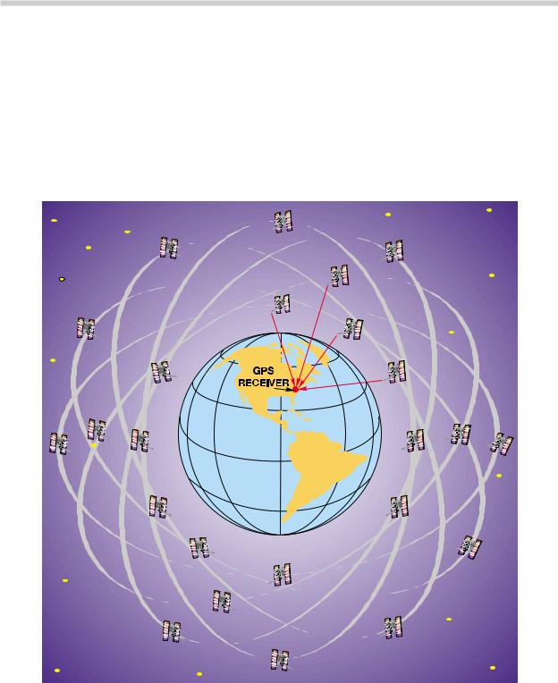
GPS - NAVIGATION SYSTEM
GLOBAL POSITIONING SYSTEM (GPS)
The BMW Navigation system operates in conjunction with the Global Positioning System (GPS). Utilization of the GPS improves the accuracy and provides redundancy for the Navigation system which also incorporates a dead reckoning system. The GPS was designed by the US Government in the 1970s for military purposes. In recent years it has been made available for civilian use.
There are 24 satellites equally divided among six orbits that are positioned 11,000 miles out in space. Each satellite continuously emits a radio signal. The signals contain short information messages including:
•The exact time the message was broadcast.
•Current latitude and longitude positions relative to the orbit.
24
On-Board Monitor and Navigation Systems
 Loading...