


Colorado RCR 168
- 1 -
8 622 401 533 / 12.98 St.
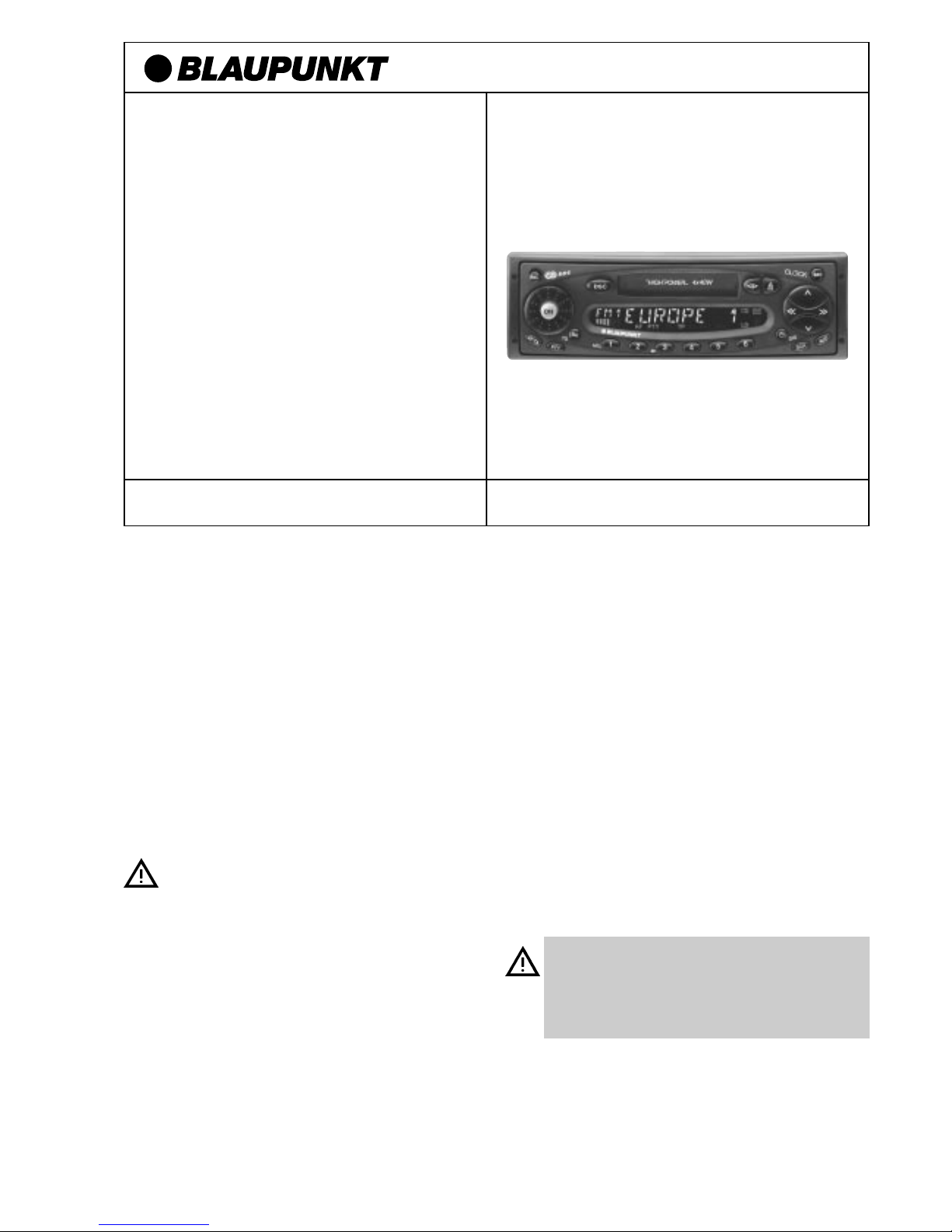
Coburg RCR 168
Colorado RCR 168
Portofino RCR 168
Vor Einbau Ihres Autoradios die Einbau- und Anschlußvorschriften lesen.
Für die Dauer der Montage und des Anschlusses
ist der Minuspol der Batterie abzuklemmen.
Hierbei sind die Sicherheitshinweise des Kfz-Herstellers
(Airbag, Alarmanlagen, Bordcomputer, Wegfahrsperren)
zu beachten.
Beim Bohren von Löchern darauf achten, daß keine Fahrzeugteile (Batterie, Kabel, Sicherungskasten) beschädigt
werden.
Der Querschnitt des Plus- und Minuskabels darf 1,5 mm
2
nicht unterschreiten. Das Gerät ist mit einer Sicherung,
10 A flink, abgesichert.
Das Seitenteil des Autoradios wird im Betrieb sehr heiß.
Es ist darauf zu achten, daß keine Kabel am Gehäuse anliegen.
In einigen Fahrzeugen liegt ein 20poliger Stecker im Einbauschacht. Dieser Stecker darf nicht am Autoradio angeschlossen werden.
In allen Fahrzeugen darf der fahrzeugseitige 8polige +/ISO-Stecker nicht direkt an Ihr Radio angeschlossen werden.
Immer Adapterkabel benutzen!
Achtung! Bei Falschanschluß erlöscht der Garantieanspruch!
Einbauanleitung (D) Seite 1
Fitting instructions (GB) page 5
Instructions de montage (F) page 7
Istruzioni di montaggio (I) pagina 9
Inbouwinstrukties (NL) pagina 11
Monteringsanvisninsida (S) sida 13
Instrucciones de montaje (E) página 15
Instruções de montagem (P) página 17
Sicherheitshinweise

- 2 -
Anschlußvorbereitung
Der folgende Abschnitt gibt Ihnen eine kleine Einbauübersicht.
Welche Autoradiokomponenten befinden sich in Ihrem Fahrzeug?
Autoradio, Lautsprecher mit Verstärker (aktiv) oder ohne Verstärker
(passiv), Antenne mit oder ohne Verstärker, Motorantenne, Scheibenantenne.
Mit welchen Steckverbindungen ist ein vorhandenes Radio adaptiert?
Sind es ISO-Norm-Anschlüsse (würden mechanisch an Ihr Radio
passen) oder Kfz-spezifische?
Wie groß ist der Querschnitt von eventuell vorhandenen Kabeln?
Fahrzeuge ohne Autoradios
Liegen bereits Lautsprecher und Stromkabel im Fahrzeug? Sind es ISONorm-Anschlüsse oder Kfz-spezifische?
Wie groß ist der Querschnitt von eventuell vorhandenen Kabeln?
Wie sieht ein ISO-Norm-Stecker aus?
Schauen Sie sich bitte die Anschlußkabel an.
Beide sind mit ISO-Norm-Steckern versehen.
ISO-Norm-Stecker können je nach Kfz-Hersteller unterschiedliche Anschlußbelegungen haben!
Für die Dauer der Montage und des Anschlusses
ist der Minuspol der Batterie abzuklemmen.
Hierbei sind die Sicherheitshinweise des Kfz-Herstellers (Airbag, Alarmanlagen, Bordcomputer, Weg
fahrsperren) zu beachten.
• Strom-Anschluß
Anschluß an Fahrzeugseitige ISO-Norm-Stecker
(siehe Fig. 5)
In allen Fahrzeugen darf der fahrzeugseitige 8polige +/- ISOStecker nicht direkt an Ihr Radio angeschlossen werden.
Immer Adapterkabel benutzen. Bei Falschanschluß erlöscht
der Garantieanspruch!
Zur Vermeidung von elektrischen Fehlanschlüssen bei fahrzeugseitigen
ISO-Steckern ist das
Universal-ISO-Adapterkabel
(Best.-Nr.
7 607 621 126) für den Plus/Minus, Plus über Zündung, Beleuchtungs-
anschluß und Plus 12 V-Schaltausgang für externe Komponenten, z. B.
Motorantenne, zu verwenden.
Zur Zeit können folgende Fahrzeuge mit ISO-Norm-Anschlüssen
mit dem
Universal- ISO-Adapterkabel
adaptiert werden: Alfa Romeo,
Citroen, Fiat, Honda, Lancia, Mercedes, Peugeot, Porsche, Renault,
Skoda.
Für andere Fahrzeuge mit ISO-Norm-Anschlüssen ist das Kfzspezifische Adapterkabel zu verwenden.
Es muß sichergestellt sein, daß der Radioanschluß im Auto bereits
werkseitig mit einer 10 A-Sicherung abgesichert ist.
Strom-Anschluß an Kfz-spezifische Stecker
(siehe Fig. 6)
Ist Ihr Radioanschluß im Auto bereits werkseitig mit einer 10 A-Sicherung
abgesichert (siehe Bedienungsanleitung oder Sicherungskasten Ihres
Kfz), so benötigen Sie nur noch das Kfz-spezifische Adapterkabel (im
Fachhandel erhältlich.
Bei weniger als 10 A-Absicherung muß wie unter "Anschluß in Fahrzeugen ohne jegliche Vorrüstung" beschrieben eingebaut werden.
Anschluß in Fahrzeugen ohne jegliche Vorrüstung
(siehe Fig. 4)
Bei Fahrzeugen ohne Autoradio-Vorrüstung oder zu geringen
Plus-/Minus-Kabelquerschnitten (< 1,5 mm
2
) ist das
ISO-Plus-/Minus-
Anschlußkabel
mit dem
Universal-Spannungsversorgungskabel
(im Fachhandel erhältlich; Best.-Nr. 7 607 884 093) zu verbauen
(siehe Fig. 4).
• Lautsprecheranschluß
Lautsprecheranschluß an fahrzeugseitige ISO-NormStecker
Bei dieser Anschlußart muß geklärt werden, ob Sie eine passive oder
aktive Lautsprechervorrüstung haben. Passiv entspricht: Lautsprecher
ohne eigenen Verstärker; aktiv mit Verstärker. Diese Info können Sie
über Ihren Kfz- oder Fachhändler beziehen.
Bei einer passiven Vorrüstung (mit 4 Ohm Lautsprecher) können Sie
den im Kfz befindlichen ISO-Stecker adaptieren. Bei Bedarf mit ISOKabel (7 607 647 093) verlängern.
Für eine aktive Vorrüstung können Sie über Ihren Fachhändler für
bestimmte Fahrzeuge entsprechende Adapterkabel beziehen.
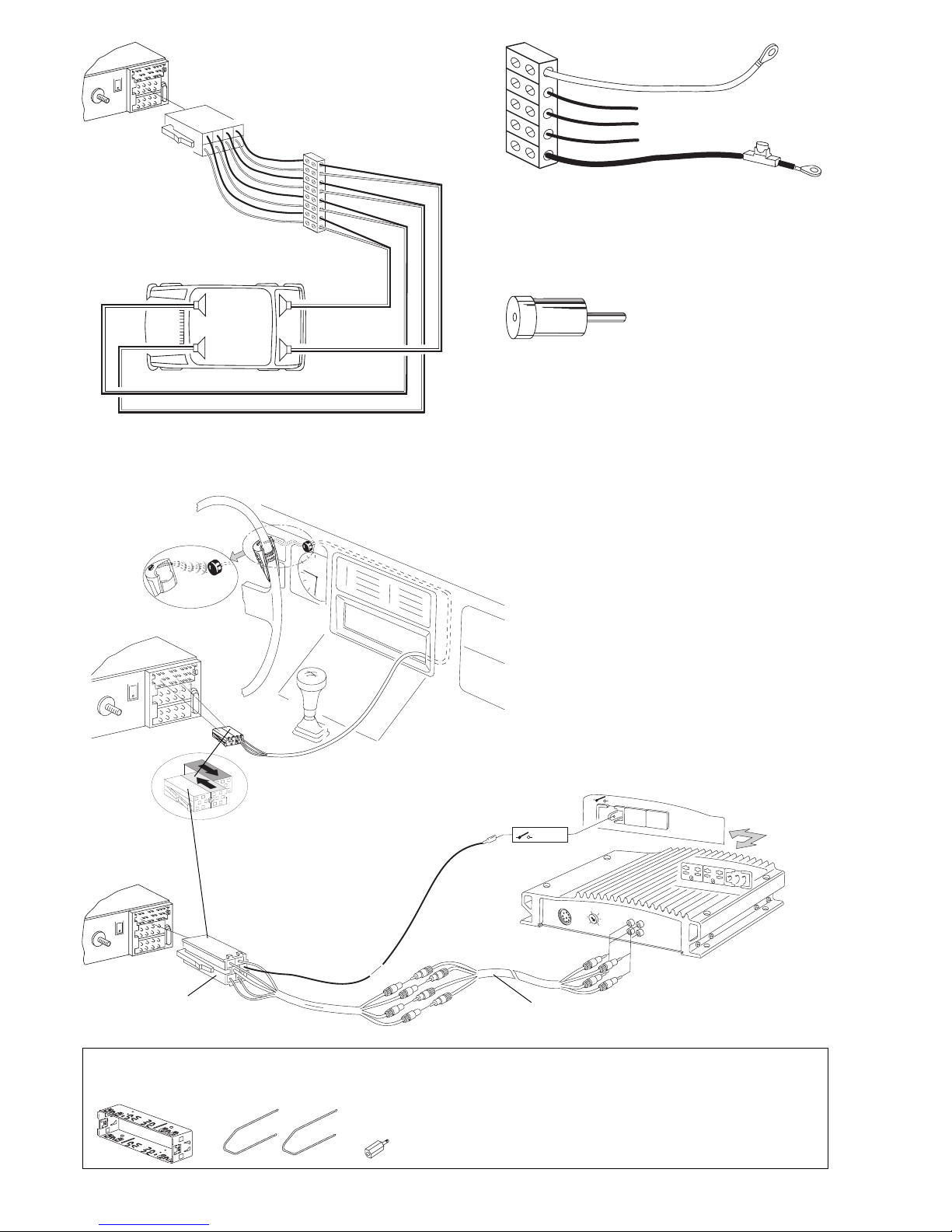
Lautsprecheranschluß in Fahrzeugen ohne jegliche Vorrüstung
Bei nachträglich eingebauten Lautsprechern verwenden Sie das
ISO-
Lautsprecherkabel
. DieVerbindung zwischen dem ISO-Lautsprecherkabel und den Lautsprechern können Sie mit Lüsterklemmen (nicht im
Lieferumfang enthalten) herstellen (siehe Fig. 7).
• Antenneneinbau
Bei neueren vorgerüsteten Fahrzeugen, z. B. VW, Seat, Audi, wird die
Versorgungsspannung für die Antenne über das Antennenkabel zugeführt. (Siehe Bedienungsanleitung vom Kfz.) Soll das Erstausrüstungsradio gegen ein handelsübliches Radio ausgetauscht werden, so ist eine
Antenneneinspeiseweiche (Best.- Nr. 7 691 290 202) von Ihrem Fachhändler zu beziehen. Antenneneinbau und Anschluß siehe Antenneneinbauanleitung. Je nach vorhandenem Antennentyp muß evt. ein
Antennenadapter verwendet werden. Im Fachhandel erhältlich.
• Autoradioeinbau
Das Autoradio wird in den vom Fahrzeughersteller vorgesehenen
Autoradioausschnitt eingebaut. Autoradioausschnitt freilegen (Ablagefach oder Blindblende ausclipsen) oder Autoradioausschnitt auf
182 x 53 mm ausarbeiten.
Für Fahrzeuge mit abweichender Einbausituation liefert Blaupunkt für
die gängigsten Fahrzeuge fahrzeugspezifische Einbausätze für
50/52 mm-Geräte. Prüfen Sie daher, welche Einbausituation im Fahrzeug vorliegt, und verwenden Sie zum Einbau gegebenenfalls einen
fahrzeugspezifischen Einbausatz.
Fahrzeugseitiger Halterahmen
Bei Fahrzeugen, die fahrzeugseitig mit einem Halterahmen ausgerüstet
sind, muß der fahrzeugseitige Halterahmen ausgebaut werden.
Einbau der Halterung
Die zum Lieferumfang dieses Autoradios gehörende Halterung ermöglicht den Einbau in Fahrzeugen mit DIN-Autoradioausschnitt von
182 x 53 mm, 165 mm Einbauraum und einer Instrumententafeldicke im
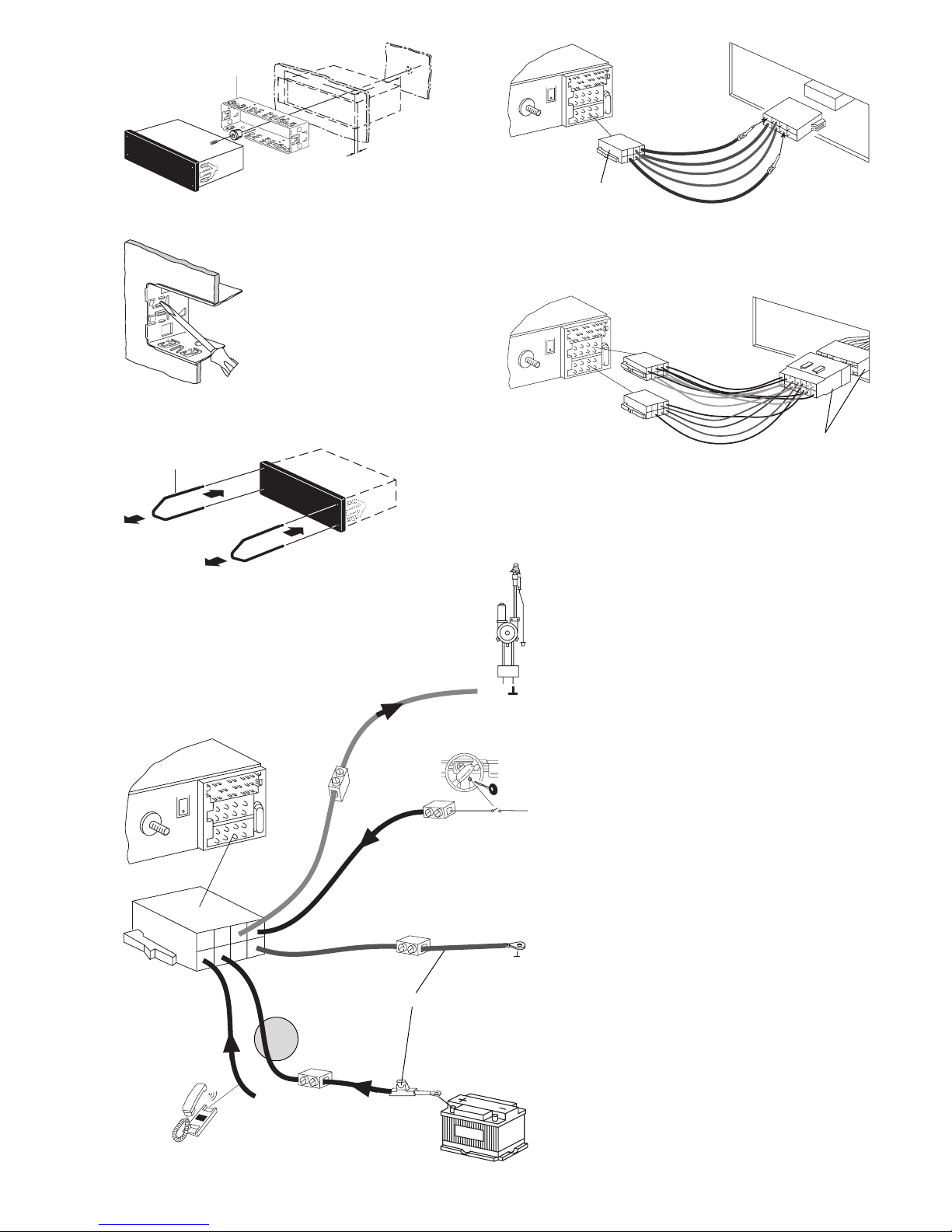
Bereich der Befestigungslaschen von 1 -20 mm (siehe Fig. 1).
Halterung in den Ausschnitt schieben und prüfen, welche Befestigungslaschen der Halterung mit einem Schraubendreher umgebogen werden
können (siehe Fig. 1, 2).
Hinweis: Möglichst alle Befestigungslaschen umbiegen.
Autoradioeinbau
Alle Stecker so weit in die Kammern einschieben, bis die seitlichen
Rastnasen einrasten. Das Autoradio von vorn in die Halterung einsetzen. Durch sanften Druck auf beide Rahmenenden einschieben, bis die
seitlichen Rastfedern rechts und links arretieren (deutliches Knacken
hörbar) (siehe Fig. 3).
Beim Einschub nicht auf Display, Knöpfe oder Schalter
drücken!
Autoradioausbau
Bügel links und rechts in die vorhandenen Löcher der Blende stecken
und so weit eindrücken, bis deutliches Knacken zu hören ist (seitliche
Federn entriegelt).
Gerät an den beiden Bügeln vorsichtig herausziehen. Jetzt können die
Anschlußkabel durch seitlichen Druck auf die jeweilige Rastnase herausgezogen werden (siehe Fig. 3).
Hinweis: Eingerastete Bügel können nur nach Herausziehen des Gerätes entfernt werden.
Anschlußzeichnungen
Anschluß in Fahrzeugen ohne jegliche Vorrüstung .................... Fig. 4
Strom-Anschluß an fahrzeugseitige ISO-Norm-Stecker. ............ Fig. 5
Anschluß an Kfz-spezifische Stecker..........................................Fig. 6
Lautsprecheranschluß 4 AL (4 Ω/ 40 W) ...................................Fig. 7
Anschluß IR-Fernbedienung RC08 ............................................. Fig. 8
Equalizer oder Amplifieranschluß (Cinch)...................................Fig. 9
8 622 401 533
- 3 -
53
182
165
8 601 310 742
1-20
Fig. 1
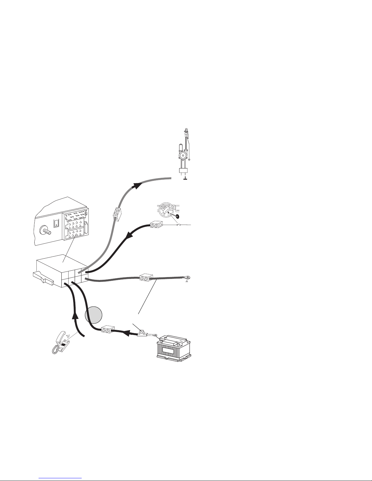
Fig. 4
Steuerkabel (Power Antenna +)
Das Steuerkabel ist der geschaltete Plusausgang für
externe Komponenten, z.B. Motorantenne,
(maximale Belastung < 150 mA).
Das Steuerkabel nicht an Klemme 15 (Plus geschaltet) oder
Klemme 30 (Dauerplus) anschließen.
Pluskabelanschluß (über Zündung geschaltet)
Wird das Pluskabel am Sicherungshalter Kl.15
(Plus über Zündschloß geschaltet) hinter der Sicherung angeschlossen, so ist das Ein- und Ausschalten des Autoradios über
Zündung möglich.
Masseanschluß (Ground)
Massekabel (Querschnitt 1,5 mm2) nicht am Minuspol der Batterie anklemmen.
Massekabel zu einem geeigneten Massepunkt verlegen
(Karosserieschraube, Karosserieblech).
Dauerplusanschluß (Kl. 30 Batterie + 12 V)
Pluskabel (gelb) mit starkem Querschnitt (1,5 mm2) zur Batterie
verlegen (Kabel nicht unmittelbar an Kabelbäumen verlegen).
Sicherungshalter zur Absicherung des Pluskabels anschließen und am Pluspol der Batterie anklemmen.
Universal-Spannungsversorgungskabel
7 607 884 093
gelb
blau
schwarz
rot
8 622 401 533
Fig. 5
10A
7 607 621 126
Fig. 2
8 601 910 002
2
2
1
1
Fig. 3
Fig. 6
10A
Kfz.-spezifische Stecker
+12V
Relais
12V
Kl.15 +12V
10A
IN
IN
IN
Out
Tel. Mute (low)
- 4 -
Mitgelieferte Montage- und Anschlußteile - Supplied Mounting Hardware - Materiel de montage fourni - Ferretería de montaje
suministrada - Componenti di fissaggio comprese nella fornitura - Meegeleverde montagematerialen - Medföljande monteringsdetaljer
- Elementos de fixação fornecidos.
8 622 401 533
10A
+12V
+12V
LR
RR
RF
LF
RRRF
LF
LR
+
-
+
-
+
-
+
-
10A
Fig. 8
Fig. 7
Antennenadapter, Antenna adapter, Adaptateur d´ántenne,
Raccordo Antenna, Antenne adapter, Antennadapter, Adaptador la antena, Adaptador de antena
8 627 105 171
15A
Universal-Spannungsversorgungskabel, Universal power
cable, Câble d‘alimentation électrique universel, Cavo di
adattamento universale, Universele voedingskabel, Universalspänningskabeln, Cable de alimentación universal, Comércio
especializado
7 607 884 093
Fig. 9
7 607 886 093
5 m
7 607 893 093
0,3 m
10A
Änderungen vorbehalten!

- 5 -
Safety notes
Before starting to mount your car radio, read the mounting and
connection instructions carefully.
Disconnect the vehicle battery’s negative terminal before making
connections.
Be sure to observe the safety notes of the automobile manufacturer
(airbags, alarm systems, on-board computers, immobilisers).
Before drilling holes, look to see what is on the other side - making
holes into the battery, wiring looms or fuse box is not recommended!
The positive lead used must have a cross-section of at least
1.5 mm
2
. The set is protected by a quick-acting 10 A fuse.
During operation of the unit, the set’s side wall may heat up
considerably.
Be sure to keep all wires away from hot parts of the housing.
In some vehicles you will find a 20-pin connector pre-fitted in the
dashboard’s installation space. This connector must not be used
for connecting the car radio!
You must not connect your car radio to an existing 8-pin
+/- ISO connector in your car. Always use the adapter cable.
Our warranty shall be vain if the connection is made
inadequately.
Preparing for the installation
The following section gives you a brief installation
overview.
What car radio components are installed in your car?
Car radio, loudspeakers with amplifier (active) or without amplifier
(passive), antenna with or without amplifier, power antenna, window
antenna.
What adapters are used for the existing car radio?
Are there standard ISO connectors (which are compatible with your
Helsinki car radio) or car specific adapters?
What cross-section do the existing cables have?
Vehicles without car radio
Are loudspeakers and power cables installed in your car? Are standard
ISO connectors or car-specific adapters used?
What cross-section do the existing cables have?
What does an standard ISO connector look like?
Take a look at the cables in the delivery. Both cables are equipped with
standard ISO connectors.
The pinning of standard ISO connectors may differ according
to auto manufacturer.
While installing and mounting this equipment, you must
disconnect the negative terminal of the battery.
You must also comply with all safety instructions given by
the auto manufacturer (airbag, alarm system, board computer,
vehicle immobilizer).
• Connecting the power supply
Connection to standard ISO adapter installed in your car
You must not connect your Helsinki car radio to an existing
8-pin +/- ISO connector in your car. Always use the adapter
cable. Our warranty shall be vain if the connection is made
inadequately.
To prevent inadequate electrical connection in vehicles equipped with
ISO connectors, use the universal ISO adapter cable
(P/N 7 607 621 126) for constant power connection, negative connection,
the positive connection via the ignition, illumination and +12 V switching
output for external components such as a power antenna.
At present, the following vehicles with standard ISO connectors
can be adapted using the universal ISO adapter cable: Alfa Romeo,
Citroen, Fiat, Honda, Lancia, Mercedes, Peugeot, Porsche, Renault,
Skoda.
Attention! For all other car models with standard ISO connector use the
car-specific adapter cable.
Make sure that the existing car radio terminal in the your car
is protected by a 10 A fuse (see Fig. 5).
Power supply to vehicle-specific connectors
If the existing car radio terminal in your car is protected by a 10 A fuse (see
operating instructins or fuse box in your car), you only need to have the
car-specific adapter cable which is available at your dealer (see Fig. 5a).
If the fuse value is less than 10 A, follow the steps described under
„Connection in vehicles without car radio wiring“.
Connection in vehicles without car radio wiring
If your car is not equipped with any car radio wiring or if the cross-section
of the existing positive/negative wires is insufficient (< 1.5 mm
2
), install
the enclosed ISO +/- cable together with the universal power supply cable
(available at your specialist dealer; P/N 7 607 884 093); see Fig. 4.
• Connecting the loudspeakers
Loudspeaker connection to the standard ISO adapter in
your car
For this type of connection, first check whether you have passive or active
loudspeakers installed in your car. Active loudspeakers have an integrated
amplifier, passive loudspeakers do not have an amplifier. For more
information contact your car dealer or audio dealer.
If your car is equipped with passive loudspeakers (4 ohms) you can adapt
the ISO connector installed in your car. Use ISO cable (7 607 647 093)
to prolong your wiring. If active loudspeakers are installed in your car, you
can order the necessary adapter cable for various vehicles from your
specialist dealer.
Loudspeaker connection in vehicles without loudspeaker wiring
For subsequently installed loudspeakers use the ISO loudspeaker cable.
Use cable connectors to link the ISO loudspeaker cable to the loudspeakers
(not included in the delivery); see Fig. 7.
• Installing the antenna
In new vehicles with antenna prefitting, e.g. VW, Seat, Audi, the power
is supplied to the antenna via the antenna cable (see user manual of your
car). If you wish to replace the original equipment for a conventional car
radio, you need to purchase an antenna duplexer (P/N 7 691 290 202)
from your specialist dealer. Information on how to install and connect
your antenna is provided in the antenna installation instructions. According
to the antenna type you wish to install, it may be necessary to use the
antenna adapter in the delivery.
• Installing the car radio
Install your car radio into the car radio compartment of your car.Uncover
the radio compartment (remove the shelf or the dummy panel) or cut the
car radio slot to a size of 182 x 53 mm. For the most common cars with
deviating installation places Blaupunkt offers specific 50-mm car radio
installation kits. Therefore, please check the car radio installation place
in your car. If required, use one of our car-specific installation kits.
Car radio sleeve or remote control installed in your car
If your vehicle is equipped with a specific car radio mounting sleeve (e.g.
Opel), it is necessary to remove the original sleeve. Steering wheel
remote controls installed in some vehicles can be adapted by means of
an interface. Contact your specialist dealer for more information.
Installing the mounting sleeve
The mounting sleeve included with this car radio is designed for installation
in vehicles with standard DIN installation compartment measuring
182 x 53 mm, 165 mm installation depth and a dashboard thickness of
1 to 20 mm in the area of the tab fasteners (see Fig. 1).Insert the car radio
into the sleeve and check which tabs on the sleeve can be bent with the
help of a screwdriver (see Fig. 1 and 2).
Note: Bend as many taps as possible.
Installing the car radio
Insert all connectors into the chambers until the side catches engage.
Place the car radio in the front of the sleeve and push it in gently on both
ends of the sleeve until the left and right side springs snap into place (you
will hear an audible click), see Fig. 3.
Do not push on the display, keys or switches!
GB
8 622 401 533
- 6 -
Removing the car radio
Insert the handles into the holes in the panel on the left and right side of
the radio and push them in until you hear an audible click (the side springs
unlock). Gently pull the unit out using both handles (see Fig. 3).
Note: Handles which have snapped into place can only be removed
after you have pulled the radio out of the compartment.
Connecting diagrams
Vehicles without car radio prefitting .......................................... Fig. 4
Power supply to standard ISO connectors................................ Fig. 5
Power supply to car-specific connectors................................... Fig. 6
Loudspeaker connection 4x 4Ω/40 watts .................................. Fig. 7
Connection of IR remote control RC 08 ...................................... Fig. 8
Equalizer or amplifier connection, (CINCH) ................................ Fig. 9
LF = left front, RF = right front
LR = left rear, RR = right rear
8 622 401 533
Control cable (power antenna +)
The control cable is the positive switching output for external
components, e.g. power antenna (max. load < 150 mA).
Do not connect the control cable to terminal 15 (positive switching
line) or to terminal 30 (constant power).
Positive connection (switched via ignition)
If you connect the positive cable of the fuse holder (terminal 15)
behind the fuse, you can turn the car radio on and off with the
ignition.
Ground connection
Do not connect the ground cable (min. cross-section 1.5 mm2) to
the negative terminal of the battery.
Connect the ground cable to a suitable ground spot (car body
screw, car body sheet). Strip off the insulation at the end of
the ground cable and attach a spade lug (resolder if necessary).
Scratch the contact point for the ground down to the bare metal
and grease it with anti-seize graphite petroleum (important for
good grounding). Screw down the ground cable.
Constant power terminal (terminal 30 battery +12 V)
Lay the positive cable (yello) with large cross-section (min.
1.5 mm
2
) to the battery (do not route any cable close to a wire
harness). Attach the fuse holder to protect the positive
cable and connect it to the positive terminal of the battery.
Universal power cable
7 607 884 093
yellow
red
black
blue
Fig. 4
This information is subject to change without notice!
+12V
Relais
12V
Kl.15 +12V
10A
IN
IN
IN
Out
Tel. Mute (low)
 Loading...