


20V max* Trimmer/Edger
INSTRUCTION MANUAL
Catalog Numbers
LST400, LST420
KEY INFORMATION YOU SHOULD KNOW:
•The guard must be installed before trimming or edging - if not, the motor will overheat.
•When replacing the line, use only .065 inch diameter ROUND line (B&D Model #AF-100 is recommended) - otherwise the trimmer will not function properly.
•Do not bump the feed head against the ground - it will disrupt the automatic feed mechanism. Thank you for choosing Black & Decker! To register your new product go to www.BlackandDecker.com/NewOwner
Please read before returning this product for any reason.
If you have a question or experience a problem with your Black & Decker purchase, go to http://www.blackanddecker.com/instantanswers
If you can’t find the answer or do not have access to the Internet,
call 1-800-544-6986 from 8 a.m. to 5 p.m. EST Mon. - Fri. to speak with an agent. Please have the catalog number available when you call.
Save this manual for future reference.
VEA EL ESPANOL EN LA CONTRAPORTADA.
INSTRUCTIVO DE OPERACIÓN, CENTROS DE SERVICIO Y PÓLIZA DE GARANTÍA. ADVERTENCIA: LÉASE ESTE INSTRUCTIVO ANTES DE USAR EL PRODUCTO.
*Maximum initial battery pack voltage (measured without a workload) is 20 volts. Measured under a workload, nominal voltage is 18.
1

A |
|
2 B |
C |
|
1
4
3
|
|
|
|
|
5 |
|
|
|
|
D |
25 |
8 |
|
E |
|
|
|
|
|
|
|
|
|
||||||
|
|
|
|
|
|
|
|
|
|
|
||||
|
|
|
|
|
|
|
|
|
|
|
26 |
|
|
|
|
|
|
|
|
|
|
10 |
11 |
|
|
|
|||
|
6 |
|
|
|
|
|
|
|
|
|
|
|
|
|
|
|
|
|
|
|
|
|
|
|
6 |
|
|
|
|
|
|
|
|
|
|
|
8 |
|
|
|
|
|
|
|
7 |
|
|
|
|
|
|
|
|
|
9 |
|
|
|
|
|
9 |
|
|
|
|
|
|
|
|
|||||
|
|
|
|
|
|
|
|
|
|
|||||
|
|
|
|
|
|
|
|
|
|
|||||
|
|
|
|
|
|
|
|
|
|
|
|
|
|
|
|
|
|
|
|
|
|
|
|
|
|
|
|
|
|
F |
|
|
|
|
|
|
|
|
|
G |
|
|
|
H |
|
|
3 |
|
|
|
|
|
|
|
|
|
|
|
5 |
|
|
|
|
|
|
|
|
|
|
|
|
|
|
|
|
|
|
|
|
|
|
|
|
|
12 |
11 |
|
|
|
|
10 |
|
|
|
|
|
|
|
|
|
10 |
|||
|
|
|
|
|
|
|
|
|
|
|
|
|
||
|
|
|
|
|
|
|
|
|
|
|
|
|
|
|
|
|
|
|
|
|
|
|
|
|
|
|
|
|
|
I |
I1 |
I2 |
J |
|
13 |
|
14 |
|
|
|
2
K |
|
|
|
L |
|
|
M |
9 |
|
|
|
|||
|
7 |
|
|
4 |
|
15 |
|
|
|
|
|
|
15 |
|
|
|
|
|
|
|
|
|
|
|
|||||
|
|
|
|
|
|
|
|
|
|
|
||||
|
|
|
|
|
|
|
||||||||
|
|
|
|
|
|
|
|
|
|
|
||||
|
|
|
|
|
16 |
|
|
|
|
|
|
|||
|
|
|
|
|
|
|
|
|
|
|
||||
|
|
|
|
|
|
|
|
|
|
|
|
|
||
|
|
|
|
|
|
|
|
|
|
|
|
|
||
|
|
|
|
|
|
|
|
|
||||||
|
|
|
|
|
|
|
Replacement: |
Spool (AF-100) |
||||||
|
|
|
|
|
|
|
|
|
|
Cap (RC-100) |
||||
|
|
|
|
|
|
|
Remplacement : Bobine (AF-100) |
|||||||
|
|
|
|
|
|
|
Repuestos: |
Capuchon (RC-100) |
||||||
|
|
|
|
|
|
|
Carrete (AF-100) |
|||||||
|
|
|
|
|
|
|
|
|
|
Tapa (RC-100) |
||||
|
|
|
|
|
|
|
|
|
|
|
|
|
|
|
N |
17 |
|
O |
|
|
P |
21 |
|
|
|||||
|
|
|
|
|
|
|
|
|
|
|||||
|
18 |
|
|
20 |
|
22 |
|
|
|
|
|
|||
|
|
|
|
|
|
|
|
|
|
|||||
|
|
|
|
|
|
|
|
|
|
|
|
|||
|
|
|
|
|
19 |
|
|
|
|
|
|
|
|
|
|
|
|
|
|
|
|
|
|
|
|
|
|
|
|
|
|
|
|
|
|
|
|
|
|
|
|
|
|
|
Q |
|
|
|
R |
|
|
|
|
|
|
|
|
|
|
24 23
SAFETY GUIDELINES - DEFINITIONS
It is important for you to read and understand this manual. The information it contains relates to protecting YOUR SAFETY and PREVENTING PROBLEMS. The symbols below are used to help you recognize this information.
DANGER: Indicates an imminently hazardous situation which, if not avoided, will result in death or serious injury.
WARNING: Indicates a potentially hazardous situation which, if not avoided, could result in death or serious injury.
CAUTION: Indicates a potentially hazardous situation which, if not avoided, may result in minor or moderate injury.
NOTICE: Used without the safety alert symbol indicates potentially hazardous situation which, if not avoided, may result in property damage.
WARNING: When using electric gardening appliances, basic safety precautions should always be followed to reduce risk of fire, electric shock, and personal injury, including the following.
IMPORTANT SAFETY WARNINGS AND INSTRUCTIONS
TO REDUCE RISK OF INJURY:
• Before any use, be sure everyone using this trimmer reads and understands all safety instructions and other information contained in this manual.
• Save these instructions and review frequently prior to use and in instructing others.
3

CAUTION: Failure to comply with the recommendations outlined in the key information section will void warranty.
WARNING: Some dust created by this product contains chemicals known to the State of California to cause cancer, birth defects or other reproductive harm. Some examples of these chemicals are:
• compounds in fertilizers
• compounds in insecticides, herbicides and pesticides
• arsenic and chromium from chemically treated lumber
To reduce your exposure to these chemicals, wear approved safety equipment such as dust masks that are specially designed to filter out microscopic particles.
WARNING: ALWAYS use safety glasses. Everyday eyeglasses are NOT safety glasses. Also use face or dust mask if trimming operation is dusty. ALWAYS WEAR CERTIFIED SAFETY EQUIPMENT:
• ANSI Z87.1 eye protection (CAN/CPA Z94.3),
• NOSH/OSHA respiratory protection.
WARNING: Always wear proper personal hearing protection that conforms to ANSI S12.6 (S3.19) during use. Under some conditions and duration of use, noise from this product may contribute to hearing loss.
Read All Instructions
WARNING:
• ALWAYS WEAR EYE PROTECTION – Wear safety glasses or goggles at all times when battery pack is installed.
• GUARD – Do not use this trimmer without guard attached.
• DRESS PROPERLY – Do not wear loose clothing or jewelry. They can be caught in moving parts. Rubber gloves and substantial rubber soled footwear are recommended when working outdoors. Don’t operate the trimmer when barefoot or wearing open sandals. Wear heavy long pants to protect your legs. Wear protective hair covering to contain long hair.
• NYLON LINE – Keep all body parts, including face, hands and feet clear of rotating nylon line at all times.
• THE ROTATING LINE PERFORMS A CUTTING FUNCTION – Use care when trimming around screens and desirable plants.
• KEEP ALL BYSTANDERS AWAY – at a safe distance from work area, especially children.
• IMPORTANT WARNING – When being used as an Edger, stones, pieces of metal and other objects can be thrown out at high speed by the line. The trimmer and guard are designed to reduce the danger. However, the following special precautions should be taken: MAKE SURE that other persons and pets are at least 100 feet (30m) away.
• TO REDUCE THE RISK of rebound (ricochet) injury, work going away from any nearby solid object such as wall, steps, large stone, tree, etc. Use great care when working close to solid objects and where necessary, do edging or trimming by hand.
• AVOID ACCIDENTALLY STARTING – Don’t carry plugged-in trimmer with finger on trigger.
• DO NOT FORCE THE Appliance – at a rate faster than the rate at which it is able to cut effectively.
• USE THE RIGHT Appliance – Do not use this trimmer for any job except that for which it is intended.
• DON’T OVERREACH – Keep proper footing and balance at all times.
• DAMAGE TO UNIT – If you strike or become entangled with a foreign object, stop trimmer immediately, remove battery, check for damage and have any damage repaired before further operation is attempted. Do not operate with a broken hub or spool.
• REMOVE BATTERY – when not in use, when replacing line, or prior to cleaning.
• AVOID DANGEROUS ENVIRONMENTAL CONDITIONS – Do not use electric appliances in damp or wet locations. Follow all instructions in this Instruction Manual for proper operation of your trimmer. Don’t use the trimmer in the rain.
• DO NOT OPERATE portable electric trimmers in gaseous or explosive atmospheres. Motors in these trimmers normally spark, and the sparks might ignite fumes.
• STORE IDLE TrimmerS INDOORS – When not in use, trimmers should be stored indoors in a dry, locked-up place out of reach of children.
• STAY ALERT – Do not operate this unit when you are tired, ill, or under the influence of alcohol, drugs, or medication.
• Replacement Parts – When servicing use only identical replacement parts.
• MAINTAIN TRIMMERS WITH CARE – Follow instructions in maintenance section. Keep handles dry, clean and free from oil and grease.
• CHECK DAMAGED PARTS – Before further use of the trimmer, a guard or other part that is damaged should be carefully checked to determine that it will operate properly and
4

perform its intended function. Check for alignment of moving parts, binding of moving parts, breakage of parts, mounting, and any other condition that may affect its operation. A guard or other part that is damaged should be properly repaired or replaced by an authorized service center unless otherwise indicated elsewhere in this manual.
• DO NOT immerse trimmer in water or squirt it with a hose. DO NOT allow any liquid to get inside it.
• DO NOT store the trimmer on or adjacent to fertilizers or chemicals.
• DO NOT clean with a pressure washer.
• Keep guards in place and in working order.
• Keep hands and feet away from cutting area.
WARNING: Do not use trimmer if the switch trigger does not turn the trimmer on or off. Any trimmer that can not be controlled with the switch trigger is dangerous and must be repaired.
SAVE THESE INSTRUCTIONS
Symbols |
|
|
|
|
|
|
||
The label on your trimmer may include the following symbols. The symbols and their |
||||||||
definitions are as follows: |
A |
amperes |
||||||
V.................. |
volts |
|||||||
Hz................ |
hertz |
W.................. |
watts |
|||||
min............... |
minutes |
|
|
|
or Ac........ |
alternating current |
||
|
|
or DC.... |
direct current |
no.................. |
no load speed |
|||
|
|
|||||||
|
................. |
|
Class I Construction |
|
|
|
.................. |
earthing terminal |
|
|
|
|
|
|
|
||
|
|
|
|
|
|
|
||
|
|
|
(grounded) |
|
|
|
................. |
safety alert symbol |
|
................. |
|
Class II Construction |
.../min or rpm... |
revolutions or |
|||
|
|
|
(double insulated) |
|
|
|
|
reciprocation per minute |
FUNCTIONAL DESCRIPTION (figure A) |
7. |
Edge Guide Wheel |
|||
1. |
On/Off Trigger Switch |
4. |
Runtime Extender |
||
2. |
Battery |
5. |
Locking Clamp |
8. |
Guard |
3. |
Auxillary Handle |
6. |
Trimmer Head |
9. |
Spool Cap |
IMPORTANT SAFETY INSTRUCTIONS FOR BATTERY CHARGERS
SAVE THESE INSTRUCTIONS: This manual contains important safety instructions for battery chargers. WARNING: Before using charger, read all instructions and cautionary markings on charger, battery pack, and product using battery pack.
WARNING: Shock hazard. Do not allow any liquid to get inside charger. WARNING: Burn hazard. To reduce the risk of injury, charge only designated Black
& Decker batteries. Other types of batteries may burst causing personal injury and damage. CAUTION: Under certain conditions, with the charger plugged in to the power supply, the charger can be shorted by foreign material. Foreign materials of a conductive nature such as, but not limited to, steel wool, aluminum foil, or any buildup of metallic particles should be kept away from charger cavities. Always unplug the charger from the power supply when there
is no battery pack in the cavity. Unplug charger before attempting to clean.
WARNING:
• DO NOT attempt to charge the battery pack with any chargers other than the ones in this manual. The charger and battery pack are specifically designed to work together.
• These chargers are not intended for any uses other than charging designated Black & Decker rechargeable batteries. Any other uses may result in risk of fire, electric shock or electrocution.
• Do not expose charger to rain or snow.
• Pull by plug rather than cord when disconnecting charger. This will reduce risk of damage to electric plug and cord.
• Make sure that cord is located so that it will not be stepped on, tripped over, or otherwise subjected to damage or stress.
5

• |
Do not use an extension cord unless it |
|
|
|
|
|||
Volts |
|
Minimum Gauge for Cord Sets |
||||||
|
is absolutely necessary. Use of improper |
|
Total Length of Cord in Feet |
|||||
|
extension cord could result in risk of fire, |
120V |
|
0-25 |
26-50 |
51-100 |
101-150 |
|
|
electric shock, or electrocution. |
240V |
|
0-50 |
51-100 101-200 |
201-300 |
||
• |
An extension cord must have adequate |
Ampere Rating |
American Wire Gauge |
|||||
|
wire size (AWG or American Wire Gauge) |
More |
Not more |
|||||
|
for safety. The smaller the gauge number |
Than |
Than |
|
|
|
||
|
of the wire, the greater the capacity of the |
0 |
- |
6 |
18 |
16 |
16 |
14 |
|
cable, that is 16 gauge has more capacity |
6 |
- |
10 |
18 |
16 |
14 |
12 |
|
than 18 gauge. When using more than one |
10 - |
12 |
16 |
16 |
14 |
12 |
|
|
extension to make up the total length, be |
12 - |
16 |
14 |
12 |
Not Recommended |
||
|
sure each individual extension contains at |
|
|
|
|
|
|
|
• |
least the minimum wire size. |
|
|
|
|
|
|
|
|
|
|
|
|
|
|
||
Do not place any object on top of charger or place the charger on a soft surface |
||||||||
|
that might block the ventilation slots and result in excessive internal heat. Place the |
|||||||
|
charger in a position away from any heat source. The charger is ventilated through slots |
|||||||
• |
in the top and the bottom of the housing. |
|
|
|
|
|
|
|
Do not mount charger on wall or permanently affix charger to any surface. The charger |
||||||||
• |
is intended to use on a flat, stable surface (i.e., table top, bench top). |
|
|
|||||
Do not operate charger with damaged cord or plug — have them replaced immediately. |
||||||||
• |
Do not operate charger if it has received a sharp blow, been dropped, or otherwise |
|||||||
• |
damaged in any way. Take it to an authorized service center. |
|
|
|
||||
Do not disassemble charger; take it to an authorized service center when service or repair |
||||||||
• |
is required. Incorrect reassembly may result in a risk of electric shock, electrocution or fire. |
|||||||
Disconnect the charger from the outlet before attempting any cleaning. This will reduce |
||||||||
• |
the risk of electric shock. Removing the battery pack will not reduce this risk. |
|
||||||
NEVER attempt to connect 2 chargers together. |
|
|
|
|
|
|||
• |
The charger is designed to operate on standard household electrical power (120 Volts). |
|||||||
|
Do not attempt to use it on any other voltage. |
|
|
|
|
|
|
|
SAVE THESE INSTRUCTIONS
IMPORTANT SAFETY INSTRUCTIONS FOR BATTERY PACKS
WARNING: For safe operation, read this manual and manuals originally supplied with tool before using the charger.
The battery pack is not fully charged out of the carton. Before using the battery pack and charger, read the safety instructions below. Then follow charging procedures outlined.
• |
Read all Instructions |
Do not incinerate the battery pack even if it is severely damaged or is completely worn |
|
|
out. The battery pack can explode in a fire. Toxic fumes and materials are created when |
• |
battery packs are burned. |
Do not charge or use battery in explosive atmospheres, such as in the presence of |
|
|
flammable liquids, gases or dust. Inserting or removing the battery from the charger may ignite |
• |
the dust or fumes. |
If battery contents come into contact with the skin, immediately wash area with mild |
|
|
soap and water. If battery liquid gets into the eye, rinse water over the open eye for 15 minutes |
|
or until irritation ceases. If medical attention is needed, the battery electrolyte for Li-ion batteries |
• |
is composed of a mixture of liquid organic carbonates and lithium salts. |
Contents of opened battery cells may cause respiratory irritation. Provide fresh air. If |
|
|
symptoms persist, seek medical attention. |
• |
WARNING: Burn hazard. Battery liquid may be flammable if exposed to spark or flame. |
Charge the battery packs only in Black & Decker chargers. |
|
• |
DO NOT splash or immerse in water or other liquids. This may cause premature cell failure. |
• |
Do not store or use the tool and battery pack in locations where the temperature may |
reach or exceed 105°F (40˚C) (such as outside sheds or metal buildings in summer).
WARNING: Never attempt to open the battery pack for any reason. If battery pack case is cracked or damaged, do not insert into charger. Do not crush, drop or damage battery pack. Do not use a battery pack or charger that has received a sharp blow, been dropped, run over or damaged in any way (i.e., pierced with a nail, hit with a hammer, stepped on). Damaged battery packs should be returned to service center for recycling.
6

WARNING: Fire hazard. Do not store or carry battery so that metal objects can contact exposed battery terminals. For example, do not place battery in aprons, pockets, tool boxes, product kit boxes, drawers, etc., with loose nails, screws, keys, etc. Transporting batteries can possibly cause fires if the battery terminals inadvertently come in contact with conductive materials such as keys, coins, hand tools and the like. The US Department of Transportation Hazardous Material Regulations (HMR) actually prohibit transporting batteries in commerce or on airplanes (i.e., packed in suitcases and carry-on luggage) UNLESS they are properly protected from short circuits. So when transporting individual batteries, make sure that the battery terminals are protected and well insulated from materials that could contact them and cause a short circuit.
NOTE: LI-ION batteries should not be put in checked baggage.
Storage Recommendations
1. The best storage place is one that is cool and dry away from direct sunlight and excess heat or cold.
2. Long-term storage will not harm the battery pack or charger as long as the battery is not depleted.
Charging Procedure
Black and Decker chargers are designed to charge Black and Decker battery packs in 5-10 hours depending on the pack being charged: LBXR2020 (5 hrs), LB2X4020 (10 hrs). The standard charger provided will charge a fully depleted battery in about 10 hours.
1. Plug the charger into an appropriate outlet before inserting the battery pack. 2. Slide the charger onto the battery pack as shown in figure B.
3. The green LED will flash indicating that the battery is being charged.
4. The completion of charge is indicated by the green LED remaining on continuously. The pack is fully charged and may be used at this time or left on the charger.
Recharge discharged batteries as soon as possible after use or battery life may be greatly diminished.
Leaving the battery in the charger
The charger and battery pack can be left connected with the green LED glowing indefinitely. The charger will keep the battery pack fresh and fully charged.
Important Charging Notes
1. Longest life and best performance can be obtained if the battery pack is charged when the air temperature is between 60°F and 80°F (16°- 27°C). DO NOT charge the battery pack in an air temperature below +40°F (+4.5°C), or above +105°F (+40.5°C). This is important and will prevent serious damage to the battery pack.
2. The charger and battery pack may become warm to touch while charging. This is a normal condition, and does not indicate a problem. To facilitate the cooling of the battery pack after use, avoid placing the charger or battery pack in a warm environment such as in a metal shed, or an uninsulated trailer.
3. If the battery pack does not charge properly:
a. Check current at receptacle by plugging in a lamp or other appliance.
b. Check to see if receptacle is connected to a light switch which turns power off when you turn out the lights.
c. Move charger and battery pack to a location where the surrounding air temperature is approximately 60°F - 80°F (16° - 27°C).
d. If charging problems persist, take the tool, battery pack and charger to your local service center.
4. The battery pack should be recharged when it fails to produce sufficient power on jobs which were easily done previously. DO NOT CONTINUE to use under these conditions. Follow the charging procedure. You may also charge a partially used pack whenever you desire with no adverse affect on the battery pack.
5. Foreign materials of a conductive nature such as, but not limited to, steel wool, aluminum foil, or any buildup of metallic particles should be kept away from charger cavities. Always unplug the charger from the power supply when there is no battery pack in the cavity. Unplug charger before attempting to clean.
6. Do not freeze or immerse charger in water or any other liquid.
WARNING: Shock hazard. Do not allow any liquid to get inside charger. Never attempt to open the battery pack for any reason. If the plastic housing of the battery pack breaks or cracks, return to a service center for recycling.
7

Installing and Removing the Battery Pack
WARNING: Make certain the lock-off button is engaged to prevent switch actuation before removing or installing battery.
To install battery pack:
Insert battery pack (2) firmly into trimmer until an audible click is heard as shown in figure C. Ensure battery pack is fully seated and fully latched into position.
To remove battery pack: Depress the battery release button in the back of the battery pack and pull battery pack out of trimmer.
This product can accept any of the batteries and chargers listed in the chart below.
LI-ION Battery Packs and Chargers
|
|
Description |
Cat. # |
Batteries: LI-ION |
LBX20 |
|
LBXR20 |
|
LBXR2020 |
|
LB2X4020 |
Chargers: LI-ION |
LCS1620 |
|
L2AFCBST |
|
L2AFC |
ASSEMBLY and Adjustment
installing the guard
WARNING: remove the battery before attempting to attach the guard, edge guide or handle. NEVER OPERATE TRIMMER WITHOUT GUARD FIRMLY IN PLACE. The guard must always be on the TRIMMER to protect the user.
• Turn the trimmer upside down so that you are looking down at the spool cap (9).
• Remove the screw from the guard with a phillips screwdriver.
• Turn the guard (8) upside down and slide it fully onto the motor housing (6). Make sure the tabs (10) on the guard engage the ribs (11) on the motor housing as shown in figure D. The locking tab (25) should have snapped into the housing slot (26).
• Continue to slide the guard on until you hear it “snap” into place.
• Using a phillips screwdriver, insert the guard screw as shown in figure E to complete the guard assembly.
• Once the guard is installed, remove the covering from the line cut-off blade, located on the edge of the guard.
Attaching the Auxiliary Handle (FIGURES F & G)
• Push the auxiliary handle (3) onto the tube (10).
• Slide the bolt (11) into the hex-shaped hole of the handle and through to the opposite side.
• Tighten the knob (12) onto the bolt by turning it clockwise.
Adjusting the position of the auxilIary handle
The auxiliary handle can be adjusted to provide optimum balance and comfort.
• Loosen the knob (12) on the bolt (11) by turning it counter clockwise.
• Gently slide the auxiliary handle up or down the tube (10) to the desired height.
• Tighten the knob onto the bolt by turning it clockwise.
Adjusting the height of the TRIMMER (FIGURE H)
CAUTION: Adjust the length of the trimmer to obtain proper working positions as shown in figure I1.
This trimmer has a telescopic mechanism, allowing you to set it to a comfortable height. To adjust the height setting (figure H):
• Release the height adjust locking clamp (5).
• Gently pull the tube (10) up or down to the desired height.
• Close the height adjust locking clamp.
8

OPERATING INSTRUCTIONS
WARNING: Always use proper eye protection that conforms to ANSI Z87.1 (CAN/CSA Z94.3) while operating this power trimmer.
WARNING: Remove the battery before making any assembly, adjustments, or changing accessories. Such preventive safety measures reduce the risk of starting the trimmer accidentally.  CAUTION: Before you begin trimming, only use the appropriate type of cutting line.
CAUTION: Inspect area to be trimmed and remove any wire, cord, or string-like objects which could become entangled in the rotating line or spool. Be particularly careful to avoid any wire which might be bent outwardly into the path of the trimmer, such as barbs at the base of a chain link fence.
Switching on and off
• To switch the trimmer on, pull the lock off button (13) (shown in inset, figure I) back toward the battery (2) and then squeeze the trigger switch (1).
• To switch the trimmer off, release the trigger switch.
OPERATING THE TRIMMER
• With the unit on, angle unit and slowly swing the trimmer side to side as shown in figure I.
• Maintain a cutting angle of 5° to 10° as shown in figure I1. Do not exceed 10° (figure I2). Cut with the tip of the line. To keep distance from hard surfaces use edge guide (7).
• Maintain a minimum distance of 24 inches (609.6 mm) between the guard and your feet as shown in figure I1. To acheive this distance adjust the overall height of the trimmer as shown in figure H.
CONVERT TO EDGING MODE
CAUTION: The wheeled edge guide should only be used when in the edging mode. The trimmer can be used in trimming mode or edging mode to trim overhanging grass along lawn edges and flower beds.
For edging, the trimmer head should be in the position shown in figure K. If it is not:
• Remove the battery from the trimmer.
• Press and hold the head-release button (14) as shown in figure J.
• While holding the auxillary handle (3), rotate the head (6) counterclockwise.
• Release the head-release button.
Note: The metal shaft and housing will only rotate in one direction.
• To return to trimming position, rotate the head clockwise back to its original position.
• Release the head-release button.
Note: The Auto Feed System may not operate correctly if wheeled edge guide is not used.
Note: You will experience faster than normal cutting line wear if the edging wheel is positioned too far from the edge with the cutting line positioned over the sidewalk or abrasive surface.
Edging
 WARNING: When being used as an Edger, stones, pieces of metal and other objects can be thrown out at high speed by the line. The trimmer and guard are designed to reduce the danger. However, MAKE SURE that other persons and pets are at least 100 feet (30m) away. Optimum cutting results are achieved on edges deeper than 2 inches (50 mm).
• Do not use this trimmer to create trenches.
• Using the edging wheel (7), guide the trimmer as shown in figure K.
• Position the edging wheel on the edge of the sidewalk or abrasive surface so the cutting line is over the grass or dirt area to be edged.
• To make a closer cut, slightly tilt the trimmer.
Accelerator Switch & Runtime Extension Mode
This string trimmer gives you the choice to operate at a more efficient speed to extend the runtime for larger jobs, or accelerate the trimmer speed for high-performance cutting (figure L).
• To extend runtime, pull the runtime extender switch (4) back toward the battery (2) into position #1. This mode is best for larger projects that require more time to complete.
• To accelerate the trimmer, push the runtime extender switch forward toward the trimmer head (6) into position #2. This mode is best to cut through heavier growth and for applications that need higher RPM.
9

NOTE: When in acceleration mode (#2), runtime will be decreased as compared to when trimmer is in extended runtime mode (#1).
Cutting Line / LINE FEEDING
Your trimmer uses .065 inch (1.65 mm) diameter, ROUND nylon line. During use, the tips of the nylon lines will become frayed and worn and the special self feeding spool will automatically feed and trim a fresh length of line. Do not bump trimmer on ground in attempt to feed line or for any other purposes.
Cutting line will wear faster and require more feeding if the cutting or edging is done along sidewalks or other abrasive surfaces or heavier weeds are being cut.
REPLACEMENT ACCESSORIES
CAUTION: Before you begin trimming, only use the appropriate type of cutting line. Use Black & Decker replacement spool Model No. AF-100, and replacement cap RC-100. Reload nylon line (either bulk or prewound replacement spool) as shown in this manual.
• USE ONLY .065 inch (1.65 mm) DIAMETER ROUND NYLON MONOFILAMENT LINE.
Do not use serrated or heavier gauge line, as they will overload the motor and cause overheating, and will not feed properly. This line is available at your local dealer or authorized service center.
• Other replacement parts (guards, spool caps, etc.) are available through Black &
Decker service centers. To find your local service location call: 1-800-544-6986 or visit www.blackanddecker.com.
 WARNING: The use of any accessory not recommended by Black & Decker for use with this trimmer could be hazardous.
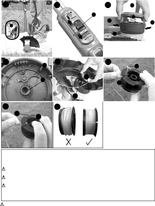
REPLACING THE SPOOL |
|
• Remove battery from trimmer. |
|
• |
Depress the tabs (15) and remove the spool cap (9) from the spool housing (16) in the |
• |
trimmer head (figure M). |
For best results, replace spool with Black & Decker model # AF-100. |
|
• Grasp empty spool with one hand and spool housing with other hand and pull spool out. |
|
• |
If lever (17) in base of housing becomes dislodged, replace in the position as shown in |
|
figure N before inserting new spool into housing. |
• Remove any dirt and grass from the spool and housing. |
|
• |
Unfasten the end of the cutting line and guide the line into the eyelet (19) figure O. |
• |
Take the new spool and push it onto the boss (18) (figure N) in the housing. Rotate the |
|
spool slightly until it is seated. The line should protrude approximately 5-3/8 inches (136mm) |
• |
from the housing. |
Align the tabs on the spool cap with the slots (20) in the housing (figure O). |
|
• |
Push the cap onto the housing until it snaps securely into place. |
|
CAUTION: To avoid trimmer damage, if the cutting line protrudes beyond the trimming |
|
blade, cut it off so that it just reaches the blade. |
REWINDING SPOOL FROM BULK LINE (use only .065 in. ROUND diameter line)
Bulk line is also available for purchase from your local retailer. NOTE: Hand wound spools from bulk line are likely to become tangled more frequently than Black & Decker factory wound spools. For best results, factory wound spools are recommended.
To install bulk line, follow the steps below:
• Remove battery from trimmer.
• Remove the empty spool from the trimmer as described in “REPLACING THE SPOOL”.
• Remove any remaining cutting line from the spool.
• Make a fold at the end of the cutting line at about 3/4 inch (19mm) (21). Feed the cutting line into one of the line anchoring slots (22) as shown in figure P.
• Insert the 3/4 inch (19mm) end of the bulk line into the hole (23) in the spool adjacent to the slot as shown in figure Q. Make sure the line is pulled tight against the spool as shown in figure Q.
• Wind the cutting line onto the spool in the direction of the arrow on the spool. Make sure to wind the line on neatly and in layers. Do not crisscross (figure R).
• When the wound cutting line reaches the recesses (24), cut the line. (figure Q).
• Fit the spool onto the trimmer as described in “REPLACING THE SPOOL”.
10
The RBRC™ Seal
The RBRC™ (Rechargeable Battery Recycling Corporation) Seal on the LI-ION battery (or battery pack) indicates that the costs to recycle the battery (or battery pack) at the end of its useful life have already been paid by Black & Decker.
RBRC™ in cooperation with Black & Decker and other battery users, has
established programs in the United States to facilitate the collection of spent LI-ION batteries. Help protect our environment and conserve natural resources by returning the spent LI-ION battery to an authorized Black & Decker service center or to your local retailer for recycling. You may also contact your local recycling center for information on where to drop off the spent battery. RBRC™ is a registered trademark of the Rechargeable Battery Recycling Corporation.
Maintenance
WARNING: To avoid serious injury, remove the battery from the trimmer before performing any maintenance.
CAUTION: To assure product SAFETY and RELIABILITY, repairs, maintenance and adjustment should be performed by authorized service centers or other qualified service organizations, always using identical replacement parts.
1. Keep the air intake slots clean to avoid overheating.
2. Your trimmer line can dry out over time. To keep your line in top condition, store spare prewound spools or bulk line in a plastic, sealable bag with a tablespoon of water.
3. Plastic parts may be cleaned by using a mild soap and a damp rag.
4. The line cutter on the edge of the guard can dull over time. It is recommended you periodically touch-up the sharpness of the blade with a file.
Troubleshooting
TRIMMER runs slowly
• Remove Battery from tool.
• Check that the spool housing can rotate freely. Carefully clean it if necessary.
• Check that the cutting line does not protrude more than approximately 5-3/8 inches (136mm) from the spool. If it does, cut it off so that it just reaches the line trimming blade.
Automatic line feed does not work
• Remove Battery from tool.
• Remove the spool cap.
• Pull the cutting line until it protrudes approximately 5-3/8 inches (136mm) from the spool. If insufficient cutting line is left on the spool, install a new spool of cutting line.
• Ensure that the line is not crisscrossed on the spool as detailed in figure R. If it is, unwind the cutting line, then wind it back on the spool neatly so that the lines do not cross.
• Ensure the beginning of the cutting line is pulled tight against the spool as shown in figure Q.
• Align the tabs on the spool cap with the cut outs in the housing.
• Push the spool cap onto the housing until it snaps securely into place.
• If the cutting line protrudes beyond the trimming blade, cut it off so that it just reaches the blade.
If the automatic line feed still does not work or the spool is jammed, try the following suggestions:
• Carefully clean the spool and housing.
• Remove the spool and check if the lever in the spool housing can move freely.
• Remove the spool and unwind the cutting line, then wind it on neatly again. Replace the spool into the housing.
Service Information
All Black & Decker Service Centers are staffed with trained personnel to provide customers with efficient and reliable service. Whether you need technical advice, repair, or genuine factory replacement parts, contact the Black & Decker location nearest you. To find your local service location, call:
1-800-544-6986 or visit www.blackanddecker.com
11
 Loading...