


D811229 ver.05 11-10-07
I
GB
F
D
E
P
AUTOMAZIONE PER CANCELLI SCORREVOLI A CREMAGLIERA |
|
|
|
|
|
|
|
|
|
|
|
|
|
|
|
|
|
|
|
|
|
|
|
|
|
|
|
|
|
|
|
|
|
|
|
|
|
AUTOMATION FOR RAK SLIDING GATES |
|
|
|
|
|
|
|
|
|
|
|
|
|
|
|
|
|
|
8 |
|
|
|
|
|
|
|
|
|
|
|
|
|
|
|
|
|
|
|
0 2 7 9 0 8 |
|
1 1 4 3 4 1 |
|||||||||||||||
|
|
|
||||||||||||||||
AUTOMATIONS POUR PORTAILS COULISSANTS Á CREMAILLÉRE AUTOMATIONENE FÜR SCHIEBEGITTERTORE MIT ZAHNSTANGE AUTOMATIZACIONES PARA PORTONES CORREDIZOS CON CREMALLERA ACCIONADOR PARA PORTÖES DE CORRER A CREMALLERA
SP4000 - SP4000 FAST
ISTRUZIONI D’USO E DI INSTALLAZIONE
INSTALLATION AND USER’S MANUAL
INSTRUCTIONS D’UTILISATION ET D’INSTALLATION
INSTALLATIONS-UND GEBRAUCHSANLEITUNG
INSTRUCCIONES DE USO Y DE INSTALACION
INSTRUÇÕES DE USO E DE INSTALAÇÃO
Via Lago di Vico 44 36015 Schio (VI) - Italy Tel. +39 0445 69 65 11 Fax. +39 0445 69 65 22 www.bft.it
e-mail: info@bft.it
ENGLISH |
USER’S MANUAL |
|
|
Thank you for buying this product, our company is sure that you will be more than satisfied with the product’s performance. The product is supplied with a “Warnings” leaflet and an “Instruction booklet”. These should both be read carefully as they provide important information about safety, installation, operation and maintenance.This product complies with the recognised technical standards and safety regulations.We declare that this product is in conformity with the following European Directives: 89/336/EEC, 73/23/EEC and 98/37/EEC (and subsequent amendments).
1) General outline
The SP4000 - SP4000 FAST controller consists of a strong gearmotor.The motor/reduction gear is an hydrodynamic coupling tipe that allows the gate leaf to start and stop smoothly, in order to avoid high structural stress. The self-braking motor allows the leaf to stop rapidly avoiding uncontrollable inertial sliding movements.
The gearmotor is joined to the gate by means of a rack. The control panel is incorporated and comprises: protection fuses, three-phase overload cutout and control unit.
The function logic allows various configurations to be set in order to better adapt the automation to the customer’s needs (e.g.: automatic closing, photocells activated on closing, etc.). To change any settings, contact a qualified technician (installer).
The irreversible type gearmotor keeps the leaf locked on closing. This way it does not need an electric lock.
A manual release system allows the leaf to be opened manually in case of power supply disconnection or inefficiency.
The installation must be provided with all the devices needed to guarantee safety of persons, animals and things, according to the provisions set out by the current standards.
2) Safety
If correctly installed and used, this automation device satisfies the required safety standards.
However, it is advisable to observe some practical rules in order to avoid accidental problems.
Before using the automation device, carefully read the operation instructions and keep them for future reference.
•Keep children, persons and things outside the automation working area, particularly during operation.
•Keep radio control or other control devices out of children’s reach, in order to avoid any unintentional automation activation.
•Do not intentionally oppose the leaf movement.
•Do not attempt to open the gate manually before to have released the motor by mean of the appropriate key.
•Do not modify the automation components.
•In case of malfunction, disconnect the power supply, activate the emergency release in order to be able to open the gate manually and request the assistance of a qualified technician.
•Before proceeding to any outside cleaning operation, disconnect the mains powers supply.
•Keep the sliding guide of the gate, photocell optical components and light signal devices clean. Check that the safety devices (photocells) are not obscured by branches or shrubs.
•Check the rack lubrication periodically.
•For any direct assistance to the automation system, request the help of a qualified technician (installer).
•Have qualified personnel checking the automation system once a year.
3) Emergency manoeuvre
When the electric supply is disconnected or the automation is faulty, the leaf must be opened manually.
3.1) Activation
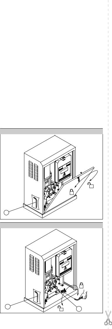
•Open the front actuator door using the key provided (fig.1).
•At the time of opening, a safety microswitch stops the actuator from operating electrically.
•Take out the release key (fig.2 ref. “C”) located inside the box and insert it in the release screw (fig.2 ref. “V”) .
•Turn the key (fig.2 ref. “C”) anticlockwise until the pinion drive system becomes completely loosen.
•This way, the pinion is released and the gate can be operated manually.
WARNING - Considering the leaf weight, it is recommended to guide the leaf manually along the entire run, and absolutely avoid to push it in an uncontrolled way.
3.2) Re-activation
•Open the actuator door with the appropriate key.
•Insert the release key (fig.2 ref. “C”) in the release screw (fig.2 ref. “V”) and turn it clockwise until it is completely tightened.
•Put release key “C” back in its place, close the actuator door and check that the automation operates electrically.
•Put the actuator door key away in a safe place known to the operators.
4) MAINTENANCE AND DEMOLITION
The maintenance of the system should only be carried out by qualified personnel regularly. The materials making up the set and its packing must be disposed of according to the regulations in force.
Batteries must be properly disposed of.
WARNINGS
Correct controller operation is only ensured when the data contained in the present manual are observed. The company is not to be held responsible for any damage resulting from failure to observe the installation standards and the instructions contained in the present manual.
The descriptions and illustrations contained in the present manual are not binding. The Company reserves the right to make any alterations deemed appropriate for the technical, manufacturing and commercial improvement of the product, while leaving the essential product features unchanged, at any time and without undertaking to update the present publication.
Fig. 1 |
C |
Fig. 2
C
v
D811229_05
- SP4000 - SP4000 FAST - Ver. 05
ENGLISH |
INSTALLATION MANUAL |
Thank you for buying this product, our company is sure that you will be more than satisfied with the product’s performance. The product is supplied with a “Warnings” leaflet and an “Instruction booklet”. These should both be read carefully as they provide important information about safety, installation, operation and maintenance.This product complies with the recognised technical standards and safety regulations. We declare that this product is in conformity with the following European Directives: 89/336/EEC and 73/23/EEC, 98/37/EEC (and subsequent amendments).
1) General safety
WARNING! An incorrect installation or improper use of the product can cause damage to persons, animals or things.
•The “Warnings” leaflet and all “Instruction booklets” supplied with this product should be read carefully as they provide important information about safety, installation, operation and maintenance.
•Scrap packing materials (plastic, cardboard, polystyrene etc) according to the provisions set out by current standards. Keep nylon or polystyrene bags out of children’s reach.
•Keep the instructions together with the technical brochure for future reference.
•This product was exclusively designed and manufactured for the use specified in the present documentation. Uses not specified in this documentation could damage the product and be dangerous.
•The Company declines all responsibility for any consequences resulting from improper use of the product, or use which is different from that expected and specified in the present documentation.
•Do not install the product in explosive atmosphere.
•The construction elements must comply with the Current Standards. The Company declines all responsibility for any consequences resulting from failure to observe good technical practice when constructing closing structures (door, gates etc.), as well as from any deformation which might occur during use.
•The installation must comply with the provisions set out by the Current Standards and always respect good technical practice.
•Disconnect the electrical power supply before carrying out any operations on the installation.Also disconnect any buffer batteries, if fitted.
•Fit an omnipolar circuit breaker or thermal magnetic circuit breaker on the mains power supply, having a contact opening distance equal to or greater than 3 mm.
•Check that a differential switch with a 0.03A threshold is fitted just before the power supply mains.
•Check that earthing is carried out correctly: connect all metal parts for closure (doors, gates etc.) and all system components provided with an earth terminal.
•Fit all the safety devices (photocells, electric edges etc.) which are needed to protect the area from any danger caused by squashing, conveying and shearing.
•Place at least one light signal device (blinker), and fix a Warning sign to the structure where it can be easily seen.
•The Company declines all responsibility with respect to the automation safety and correct operation when other manufacturers’ components are used.
•Only use original parts for any maintenance or repair operation.
•Do not modify the automation components, unless explicitly authorised by the company.
•Instruct the product user about the control systems provided and the manual opening operation in case of emergency.
•Do not allow persons or children to remain in the automation operation area.
•Keep radio control or other control devices out of children’s reach, in order to avoid unintentional automation activation.
•The user must avoid any attempt to carry out work or repair on the automation system, and always request the assistance of qualified personnel.
•Anything which is not expressly provided for in the present instructions, is not allowed.
•Installation must be carried out using the safety devices and controls prescribed by the EN 12978 Standard.
2) General outline
The SP4000 - SP4000 FAST controller consists of a strong gearmotor.The motor/reduction gear is an hydrodynamic coupling tipe that allows the gate leaf to start and stop smoothly, in order to avoid high structural stress. The self-braking motor allows the leaf to stop rapidly avoiding uncontrollable inertial sliding movements.
The gearmotor is joined to the gate by means of a rack. The control panel is incorporated and comprises: protection fuses, three-phase overload cutout and control unit.
14 - SP4000 - SP4000 FAST - Ver. 05
The function logic allows various configurations to be set in order to better adapt the automation to the customer’s needs (e.g.: automatic closing, photocells activated on closing, etc.). To change any settings, contact a qualified technician (installer).
The irreversible type gearmotor keeps the leaf locked on closing. This way it does not need an electric lock.
A manual release system allows the leaf to be opened manually in case of power supply disconnection or inefficiency.
The installation must be provided with all the devices needed to guarantee safety of persons, animals and things, according to the provisions set out
by the current standards. |
|
The gearmotor (fig.1) comprises : |
|
MF) |
Motor with electric brake |
G) |
Hydrodynamic motor/reduction gear coupling |
R) |
Reduction gear in oil bath with worm screw/wheel |
MS) |
Opening door safety microswitch |
S) |
Electromechanical end-of-stroke unit |
P) |
Pinion |
Q) |
Control panel |
SB) |
Emergency release |
C) |
Box with lockable door. |
3) Technical specifications |
|
|
|
3.1) SP4000 - SP4000 FAST |
|
|
|
Power supply....... |
: three-phase+N 400V three-phase 230V ±10% 50Hz (*) |
||
Motor revolutions.................................................... |
|
|
....: 1400min-1 (SP 4000) |
......................................................................... |
|
|
2800 min-1 (SP 4000 FAST) |
Absorbed power.............................................................................. |
|
|
: 1500W |
Max absorbed power........................................ |
|
: 2.6A (400V); 4.84A (230V) |
|
Protection.............................................. |
|
|
: overload cutout wired in the panel |
Insulation class......................................................................................... |
|
|
: F |
Reduction ratio..................................................................................... |
|
|
: 1/46 |
Output revolutions.......................................................... |
|
: 30min-1 (SP 4000) |
|
............................................................................. |
|
|
60 min-1 (SP 4000 FAST) |
Pinion pitch.................................................................. |
|
|
: m=6mm z=18 teeth |
Max leaf weight............................................ |
|
|
: 40000N (~4000kg) (SP 4000) |
.......................................................... |
|
: 10000N (≈1000kg) (SP 4000 FAST) |
|
Leaf speed................................................................ |
|
|
: 10.1m/min (SP 4000) |
...................................................................... |
|
|
: 20.2 m/min (SP 4000 FAST) |
Impact reaction...................................................... |
|
|
: stop (with electric edge) |
Reduction gear lubrication...................................................................... |
|
: oil |
|
Manual manoeuvre............................... |
|
: multi-disk mechanical key release |
|
No. manoeuvres in 24 hours......................................... |
|
: continuous service |
|
Control unit.......................................................... |
|
|
: SIRIO TEL with interface |
Environmental conditions........................................... |
|
: from -15°C to +50°C |
|
Degree of protection............................ |
: IP X4(Electrical components:IP 54) |
||
Dimensions.................................................................................. |
|
|
: See fig. 2 |
Controller weight................................................................... |
|
|
: 850N (~86kg) |
(*) 230V three-phase power supply available |
|||
3.2) SIRIO TEL |
|
|
|
Power supply (*):.................... |
400 vac three-phase + /230 vac three-phase |
||
Mains - low voltage insulation:........................................ |
|
> 2MOhm 500Vdc |
|
Mains - low voltage dielectric strength:....................................... |
3750Vac 1' |
||
Power supply to accessories:..................................................... |
|
24Vac/0,5A |
|
Gate-open warning light:.................................................................... |
|
24/3W |
|
Blinker:......................................................................................... |
|
|
230V/40W |
4) Preliminary checks
Check that the gate structure is conform to whatever is prescribed by the current standards, and in particular that:
•the gate sliding track is linear and horizontal, and the wheels are suitable for supporting the gate weight;
•the gate manual operation can be carried out smoothly along its entire run, and there is no excessive side slipping;
•a correct play is provided between the upper guide and the gate to ensure regular noiseless movement;
•the gate stops on opening and closing are or can be positioned;
•the established position for gearmotor fixing allows the emergency
manoeuvre to be carried out smoothly and safely.
Inthecasewheretheelementscheckeddonotmeettheaboverequirements, proceed to carrying out the necessary corrective actions or replacements.
WARNING: Remember that control devices are intended to facilitate gate use, but can not solve problems due to any defects or deficiency resulting from failure to carry out gate maintenance.
Take the product out of its packing and inspect it for damage. Should it be damaged, contact your dealer.Remember to dispose of its components (cardboard, polystyrene, nylon, etc.) according to the current prescriptions.
D811229_05
D811229_05
INSTALLATION MANUAL |
ENGLISH |
5) Base plate anchoring
1)Identify a suitable position, and check that there are no underground cables or pipes.
2)Arrange for a pit or column near the fixing plate for the various connections, in order to have a single raceway with a 60-80mm diameter reaching the actuator.
3)The anchoring base, which is already assembled (fig. 3), must be positioned with the gear label facing the gate.
4)Dig a hole having the size specified in fig. 3, where to cement the base plate log bolts to fix the actuator with. If the sliding track is already there, digging must be partly carried out in the track foundation casting. This way, should the track sag, the gearmotor base would also lower, thus maintaining the play between pinion and rack (approximately 4-5mm). In order to keep the base plate correct position during installation, it may be useful to weld two iron rods under the track, and then weld the log bolts onto them (fig. 3).
5)Position the base plate according to the mesurement specified in fig. 4. The pinion symbol printed on the base plate must be visible and directed towards the gate. This also ensures the correct positioning of the pipe or the cable channel for electrical connections.
6)Let the single pipe or cable channel provided for electric cables protrude from the base plate.
7)Proceed to casting the concrete.
8)Accurately check that:
-The positioning dimensions (fig. 4) are correct,
-The base plate to be levelled in both directions,
-The 4 stud threads and the base are free from cement.
-Let the casting harden.
Note: The actuator must be fixed to the foundation base which comprises a steel plate treated against corrosion and the log bolts to anchor the plate to the ground.
WARNING: Do not loosen the nuts securing the log bolts. After cementing, use a dynamometric wrench to check that these are tightened with a 70Nm torque.
Fig. 5 shows dimensions and holes to be drilled in the actuator base.
6) Gearmotor fixing
When the casting has hardened, make all the mains and accessory connection cables go through, letting them protrude from the foundation plate by approximately 1 metre.
Observe fig. 6 and proceed as follows:
1)Open the door and unscrew the 4 screws which fix the protective cover to the base (fig. 1 ref. ”C”) using a suitable key.
2)Position the actuator over the plate, and insert all the cables or pipes in the appropriate hole (fig. 6), and the tie rods in the fixing slots.
3)Thread a flat spacer washer, a spring washer and an M12 nut on each one of the four base tie rods. Leave the nuts loose for correct positioning.
4)Fit the four levelling dowels (fig. 7 ref. “G”) and adjust them so as to level (fig. 7 ref. “L”) the actuator, which should be raised by approximately 8- 10mm with respect to the foundation base.
5)Slide the actuator in the appropriate slots, find its final position respect-
ing the measurements specified in fig. 4, and fix the four nuts (fig. 7 ref. “T”) which secure the actuator to the foundation plate and the levelling dowel lock nuts.
Note: the rack teeth should mesh with the pinion along their entire width.
7) Arrangement for rack fitting
A steel rack having a pitch of m=6mm teeth and cross section of at least 30x30mm must be fixed to the gate. It is usually supplied in 2-metre elements.
As far as length is concerned, this must take into account the passage space, the pinion meshing section and also the space for fixing the runners controlling the end-of-stroke.
Rack fixing must be suitable for the type of gate used. As an example, this paragraph describes the rack fixing method by means of welded angle bars (fig. 8).
WARNING – Welding is to be carried out by a skilled operator wearing all personal protective equipment prescribed by the current safety standards. During welding operations, use suitable screens to protect the actuator from any welding spits.
7.1) Fitting
1)Prepare some rack fixing angle bars using adequately-sized “L” shaped sections. They must be fixed or welded at a distance of approximately 80-100cm.
2)Bring the gate to a fully closed position (or open, if more practical) by hand.
3)Activate the emergency release (See paragraph on “EMERGENCY MANOEUVRE”).
4)Rest the end of one rack element on the control pinion, keeping it levelled (parallel to the track).
5)Rest one angle bar on the rack and secure it with a suitable clamp; while keeping the rack level and lined up with the pinion profile, spot weld the angle bar to the gate and then the rack to the angle bar (fig. 8).
6)Push the leaf by hand as far as the other end of the rack, centre the rack into the pinion teeth, rest one angle bar on the rack, secure it with a suitable clamp, spot weld it to the gate and then weld the rack to the angle bar.
7)While sliding the leaf by hand, position and lightly spot weld the intermediate angle bars (one every 80-100cm).
8)Slide the rack element out of the pinion, and strongly weld the angle bars and the rack.
WARNING: Do not weld the joints of the rack elements together.
9)Position another rack element next to the one welded previously. Couple the joints of the two elements by opposing a piece of rack (fig. 9) to keep the correct pitch, and secure everything using suitable clamps.
10)Proceed to welding and positioning all the elements by repeating the
procedure described above. 8) Pinion adjustment
Having finished fixing the rack, the rack-pinion play must be adjusted as follows, with reference to fig. 10.
1)Slacken the four “G” dowels at the base of the actuator by approximately 4 mm.
2)Check levelling by means of a level.
3)Check that the rack meshes with the pinion all along its width and the leaf stroke.
4)Fix the 4 log-bolts nuts (fig. 10 ref. “T”) which fasten the actuator to the ground.
5)Fix the 4 levelling dowel lock nuts (fig. 10 ref. “G”).
6)Check the slack between pinion and rack along the whole rack length; if necessary, adjust the play between pinion and rack.
WARNING – Remember that the life of the rack and pinion largely depends on the mesh.
9) Fitting of end-of-stroke runners
These are used to control the opening/closing limit microswitches.They can be directly welded on the rack or fixed by means of screws.
When fixed by screws, the runner position can be re-adjusted later.
WARNING - The automation must not be electrically operated without the end-of-stroke runners.
This operation is to be carried out with the emergency release activated and mains power supply disconnected.
1)If the mains power is already connected, ensure that the automation switch is down.
2)Activate the emergency release as described in the respective paragraph.
3)Push the leaf fully open by hand, and stop it approximately 4-5cm before the required stop point.
4)Connect an ohmmeter to the control unit terminals related to the opening limit switch (SWO) by consulting the paragraph on “Terminal connections”.Check the instrument reading by pushing the end-of-stroke control lever by hand towards the opening direction (the instrument must show interruption of continuity).
5)Position the end-of-stroke runner on the rack and push it against the end- of-stroke lever (fig. 11 ref. “P”) until the instrument signals microswitch intervention.
6)After identifying the runner position, fix it by spot welding. In the case of screw fixing, mark the identified position and proceed accordingly.
7)Connect the instrument to the control unit terminals related to the closing limit switch (SWC). Check the instrument reading by pushing the end-of-stroke control lever by hand towards the opening direction (the instrument must show interruption of continuity).
8)Push the leaf fully closed by hand. Stop the leaf by approximately 4- 5cm from the required closing point. If necessary, take into account any clearance (fig.12) or impact device (fig.13 - ref.“CS”) needed, according to the provisions set out by current national standards.
9)Position the end-of-stroke runner on the rack and push it against the end- of-stroke lever until the instrument signals microswitch intervention.
10)After identifying the runner position, fix it by spot welding. In the case of screw fixing, mark the position and proceed accordingly.
11)Disconnect the instrument, restore motorised operation (see paragraph on “Emergency release”). Correct electrical limit switch intervention is to be checked after carrying out electrical connections and checking the “DIRECTION OF ROTATION” (see relevant paragraph). If the position is correct, secure the welded runners with sturdy welding, or check that the fixing screws to be well tightened (depending on the chosen fixing way).
SP4000 - SP4000 FAST - Ver. 05 - 15

ENGLISH |
INSTALLATION MANUAL |
IMPORTANT:In the case where the leaf keeps sliding after the stop command, the moulded end section of the runner (fig. 11 ref. “A”) can be lengthened so as to stop the runner from going past the end-of-stroke point.
WARNING!To avoid inefficiency, or damage to the automation, keep always a space of 4-5cm before the required opening/closing end positions (fig. 12).
10) Gate backstops
DANGER - The gate must be provided with mechanical backstops both on closing and opening (fig. 12 ref. “F”) in order prevent it from coming out of the upper guide.
The mechanical stops must be sturdily secured to the ground, a few centimetres beyond the electric stop point.
11) Electrical installation set-up
Lay out the electrical installation as shown in fig.13, with reference to the CEI 64-8 and IEC 364 provisions complying with the HD 384 and other national standards in force for electrical installation.
WARNING – Check the actuator rating.
For the 400V three-phase version, connect the mains using a multipolar R-S-T-N+EARTH cable having a minimum cross section of 2.5 sq mm and complying with the current national standards (e.g.: H07RN-F type).
For the 230V three-phase version, connect the mains using a multipolar R-S-T+EARTH cable having a minimum cross section of 2.5 sq mm and complying with the current national standards (e.g.: H07RN-F type).
Connect the control and safety devices in compliance with the previously mentioned technical installation standards.
The mains power supply connections must be kept totally separate from the auxiliary connections.
Fig.13 shows the number of connections and the cross section for approximate lengths of 100 metres; in case of greater lengths, calculate the cross section for the true automation load:
The main automation components are (fig. 13):
IType-approved omnipolar circuit breaker with adequate capacity and at least 3 mm contact opening, provided with protection against overloads and short circuits, suitable for cutting out automation from the mains.If not already installed, place a type-approved differential
|
switch with a 0.03A threshold before the automation system |
QR |
Control panel and incorporated receiver |
S |
Key selector |
AL |
Blinker with tuned antenna |
M |
Actuator |
E |
Electric lock |
P |
Control buttons |
CS |
Electric edge |
CC |
Edge control |
Fte, Fre |
Pair of external photocells |
Fti, Fri |
Pair of internal photocells |
CF |
Posts |
T |
1-2-4 channel transmitter. |
WARNING! Operator without torque limiter: install the actuator with appropriate safety systems (eg. device type E item 5.5.1 of
EN12453:2000 standard)
12) Control panel connections
After the appropriate electric cables have been passed through the raceways and fixed to the various automation components in the chosen points, these must be connected according to the indications and diagrams shown in the relevant instruction manuals.
Connect the phase, neutral (230V three-phase excluded), and earth (compulsory)cables.Theprotection(earth)wire,havingayellow/greeninsulatingsheath, must be connected to the appropriately marked terminals provided  .
.
The automation device is to be operated after all the safety devices have been connected and checked.
Fig. 14-15 shows the wiring diagram of the panel fitted to the actuator. Here follows a description of the terminals to be connected to the control panel (fig.14-15) including the SIRIO TEL mod. unit (fig. 16).
Panel
N-R-S-T+ EARTH 400Vac ±10%, 50Hz, three-phase panel power supply R-S-T+ EARTH 230Vac ±10%, 50Hz, three-phase panel power supply
SIRIO TEL control unit terminal board (fig.16) N.B.:
The board is supplied with a series of previously bridged terminals.
The jumpers refer to the following terminals: 26-29, 26-30, 26-31, 26-35. If these terminals are not used, leave them bridged.
JP1 - THREE-PHASE 400V
1-2-3-4 Three-phase power supply+neutral 400V (1N - 2R - 3S - 4T). 8-9 230Vac output for blinker 40W max.
16 - SP4000 - SP4000 FAST - Ver. 05
JP1 - THREE-PHASE 230V
2-3-4 Three-phase power supply 230V (2R - 3S - 4T). 8-9 230Vac output for blinker 40W max.
JP2
10-11 24Vac (3W) output for gate-open warning light.
11-12 24Vac power supply to accessories and safety devices which are not checked.
12-13 24VTx power supply only for safety device transmitters which are checked.
14LOOP1 input for safety device check ring (see fig.5).
15LOOP2 input for safety device check ring (see fig.5).
16-17 Second radio channel output for two-channel receiver board (n.o.).
18-19 Antenna input for radio receiver board (18 signal, 19 braid).
JP7
20-21-22
23-24-25 Outputs for the connection of safety devices which are to be checked (see fig.5).
JP4
26-27 START button (n.o.).
26-28 Block button (n.c.). Additional buttons to be connected in series with one another.
26-29 Photocell contact input (n.c.). If not used, leave on. If used while checking, observe wiring diagram in fig.5.
26-30 Opening limit switch (n.c.). If not used, leave bridged. 26-31 Closing limit switch (n.c.). If not used, leave bridged. 26-32 Pedestrian access button (n.o.).
26-33 Open button (n.o.).
26-34 Close button (n.o.).
26-35 IR edge contact input (n.c.). If not used, leave bridged. JP6 1-2 channel radio receiver board connector.
12.1) Check of direction
WARNING! Before supplying the system with power, it is compulsory to check the “DIRECTION OF ROTATION” as described below.
1)Activate the release as described in the paragraph on “EMERGENCY MANOEUVRE”.
2)Bring the leaf to the fully closed position by hand (limit microswitch pressed).
3)When the system is supplied with power (control unit door and box open), the SWC LED must be off.
If the LED are on, the SWO and SWO limit switch connections must be reversed in the control unit.
4)Bring the leaf to the half-way position by hand.
5)Restore motorised operation (“EMERGENCY MANOEUVRE”) and reposition the box door to close the respective safety contact.
6)Disconnect the mains power supply temporarily to reset the control unit.
7)At the first start command, the control unit always carries out the opening manoeuvre; check the following:
a)if the gate moves along the opening direction, the direction of rotation of the actuator is correct;
b)if the gate moves along the closing direction, disconnect the mains power supply and invert two phases in the control unit power supply terminal board.
8)Connect the mains power supply and carry out a complete checking cycle.
13) CONNECTION TO SAFETY DEVICES
•In case of standard devices with 4 terminals and without self-diagnostic function, the connection can be carried out without verification as indicated in point 13.1.
•In case of devices featuring internal self-diagnostic function, refer to point 13.2.
•Thestandarddeviceswith5terminalsandwithoutself-diagnosticfunctioncan be included in the control and self-diagnostic cycle observing the instructions given in point 13.3.
13.1) Safety devices WITHOUT SELF-DIAGNOSIS
Connections must be carried out as shown in fig. 18. Keep the Dip-switches 9 and 10 in the ON position (standard setting). The tripping contacts of a group of devices of the same type, must be connected in series with one another.
13.2) Safety devices WITH INTERNAL SELF-DIAGNOSIS
Connections must be carried out as shown in fig.18. Keep the Dip-switches 9 and 10 in the ON position (standard setting).The tripping contacts of several devices of the same type, must be connected in series.
D811229_05
 Loading...