


D811492_02 20-02-07
|
AUTOMAZIONI PER PORTE BASCULANTI E SEZIONALI |
|
|
|
|
|
|
|
|
|
|
|
|
|
|
|
|
|
|
|
|
I |
|
|
|
|
|
|
|
|
|
|
|
|
|
|
|
|
|
|
|
|
|
|
|
|
|
|
|
|
|
|
|
|
|
|
|
|
|
|
|
|
|
|
|
GB |
AUTOMATION FOR OVERHEAD AND SECTIONAL GARAGE DOORS |
|
|
|
|
|
|
|
|
|
|
|
|
|
|
|
|
|
|
|
|
|
AUTOMATION POUR PORTES BASCULANTES ET SECTIONALES |
8 |
|
|
|
|
|
|
|
|
|
|
|
|
|
|
|
|
|
|
|
F |
027908 |
|
288127 |
||||||||||||||||||
|
|
|
|
|
|
|
|
|
|
|
|
|
|
|
|
|
|
|
|
|
|
DGARAGENTORANTRIEB FÜR SCHWING UND SEKTIONALTORE
EAUTOMATIZACIONES PARA PUERTAS BASCULANTE Y SECCIONALES
P AUTOMATIZAÇÕES PARA PORTAS BASCULANTES DE MOLAS E SECCIONAIS
BOTTICELLI
VENERE
ISTRUZIONI D'USO E DI INSTALLAZIONE
INSTALLATION AND USER'S MANUAL
INSTRUCTIONS D'UTILISATION ET D'INSTALLATION
MONTAGEund BEDIENUNGSANLEITUNG
INSTRUCCIONES DE USO Y DE INSTALACION
INSTRUÇÕES DE USO E DE INSTALAÇÃO
Via Lago di Vico, 44 36015 Schio (VI) Tel.naz. 0445 696511 Tel.int. +39 0445 696533 Fax 0445 696522 Internet: www.bft.it E-mail: sales@bft.it

D811492_02
- BOTTICELLI VENERE
ENGLISH |
|
|
|
|
|
|
|
|
USER’S MANUAL |
|
02 |
|||||||||||
Thank you for buying this product, our company is sure that you will be more |
|
not been released by pulling the appropriate wire connected to the carriage |
||||||||||||||||||||
than satisfied with the product’s performance. The product is supplied with |
|
(fig.1), or the external lock (SM1 or SET/S fig.2-fig.3) activated. |
|
D811492 |
||||||||||||||||||
|
|
|
||||||||||||||||||||
a “Warning” leaflet and an “ Instruction booklet ”. These should both be |
• Do not modify the automation components. |
|
|
|||||||||||||||||||
read carefully as they provide important information about safety, installa- |
• |
In case of malfunction, disconnect the power supply, activate the emer- |
||||||||||||||||||||
tion, operation and maintenance. This product complies with the recognised |
|
gency release to gain access to the automation device and request the |
||||||||||||||||||||
technical standards and safety regulations. We declare that this product is in |
|
assistance of a qualified technician (installer). |
|
|
||||||||||||||||||
conformity with the following European Directives: 89/336/EEC, 73/23/EEC, |
• |
Before proceeding to any external cleaning operation, disconnect |
the |
|||||||||||||||||||
98/37/EEC, 99/05/EEC (and subsequent amendments). |
|
|
mains powers supply. |
|
|
|||||||||||||||||
1)GENERAL OUTLINE |
|
• Keep the photocell optical components and luminous signal indication de- |
||||||||||||||||||||
|
|
vices clean. Check that the safety devices (photocells) are not obscured by |
||||||||||||||||||||
The BOTTICELLI system is compatible with the EElink protocol for fast in- |
|
branches or shrubs. |
|
|
||||||||||||||||||
stallation and maintenance. It is suitable for motorising sectional doors, pro- |
• For any direct assistance to the automation system, request the assistance |
|||||||||||||||||||||
truding fully retracting spring operated overhead doors and counterweight |
|
of a qualified technician (installer). |
|
|
||||||||||||||||||
overhead doors provided with an appropriate towing arm. The overhead door |
• Have qualified personnel check the automation system once a year. |
|
|
|||||||||||||||||||
must not be higher than 3 metres. It is easy to install and fast to fit and does |
• Check the installation frequently, in particular cables, springs and supports |
|||||||||||||||||||||
not need the door to be modified. The irreversible gearmotor keeps the door |
|
to find out any unbalance, sign of wear or damage. Do not use the operator |
||||||||||||||||||||
locked in the closing position. The control unit is builtin. It controls the opera- |
|
in the case where any repairs or adjustments are required, given that an |
||||||||||||||||||||
tion relays and the safety devices (photocell, rubber skirt) before performing |
|
installation malfunction or an incorrectly balanced door could cause inju- |
||||||||||||||||||||
every manoeuvre. |
|
|
ries. |
|
|
|||||||||||||||||
This product was designed to motorise the types of door mentioned |
• Once a month, check that the motor reverses when encountering on obstacle |
|||||||||||||||||||||
above. Any other use is considered contrary to that intended by the |
|
50 mm away from the floor. Should operation show to be incorrect, request |
||||||||||||||||||||
manufacturer who,therefore,cannot be held responsible for any injuries |
|
the assistance of a qualified technician, given that an incorrect adjustment |
||||||||||||||||||||
to persons or animals,or damage to things which might derive from |
|
could be dangerous. |
|
|
||||||||||||||||||
misuse. |
|
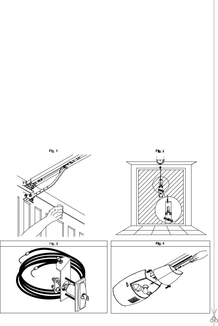
3) EMERGENCY MANOEUVRE |
|
|
||||||||||||||||||
2)SAFETY |
|
|
|
|||||||||||||||||||
|
In case of electric power failure or system malfunction, the manoeuvre must |
|||||||||||||||||||||
If correctly installed and used, this automation device satisfies the required |
be carried out manually by pulling the wire connected to the carriage, as in |
|||||||||||||||||||||
safety level standards. However, it is advisable to observe some practical rules |
fig.1. For garages which are not provided with a second exit, it is compulsory |
|||||||||||||||||||||
in order to avoid accidental problems. Before using the automation device, |
to fit an external key release device like Mod. SM1 (fig.2) or Mod. SET/S |
|||||||||||||||||||||
carefully read the operation instructions and keep them for future reference. |
(fig.3). |
|
|
|||||||||||||||||||
• Keep children, persons and things outside the automation working area, |
WARNING: If the door is not correctly balanced, activation of the carriage |
|||||||||||||||||||||
particularly during operation. |
|
manual release could provoke an uncontrolled door movement. |
|
|
||||||||||||||||||
• Keep radio control or other control devices out of children’s reach, in order |
4) BULB REPLACEMENT |
|
|
|||||||||||||||||||
to avoid any unintentional automation activation. |
|
|
|
|||||||||||||||||||
• Do not intentionally oppose the leaf movement. |
|
To replace the courtesy light bulb, remove its transparent cover (fig.4). |
|
|
||||||||||||||||||
• Do not attempt to open the door manually, if the internal locking system has |
WARNING: Only 24V 25W max E14 bulbs must be used. |
|
|
|||||||||||||||||||
|
|
|
|
|
|
|
|
|
|
|
|
|
|
|
|
|
|
|
|
|
|
|
|
|
|
|
|
|
|
|
|
|
|
|
|
|
|
|
|
|
|
|
|
|
|
|
|
|
|
|
|
|
|
|
|
|
|
|
|
|
|
|
|
|
|
|
|
|
|
|
|
|
|
|
|
|
|
|
|
|
|
|
|
|
|
|
|
|
|
|
|
|
|
|
|
|
|
|
|
|
|
|
|
|
|
|
|
|
|
|
|
|
|
|
|
|
|
|
|
|
|
|
|
|
|
|
|
|
|
|
|
|
|
|
|
|
|
|
|
|
|
|
|
|
|
|
|
|
|
|
|
|
|
|
|
|
|
|
|
|
|
|
|
|
|
|
|
|
|
|
|
|
|
|
|
|
|
|
|
|
|
|
|
|
|
|
|
|
|
|
|
|
|
|
|
|
|
|
|
|
|
|
|
|
|
|
|
|
|
|
|
|
|
|
|
|
|
|
|
|
|
|
|
|
|
|
|
|
|
|
|
|
|
|
|
|
|
|
|
|
|
|
|
|
|
|
|
|
|
|
|
|
|
|
|
|
|
|
|
|
|
|
|
|
|
|
|
|
|
|
|
|
|
|
|
|
|
|
|
|
|
|
|
|
|
|
|
|
|
|
|
|
|
|
|
|
|
|
|
|
|
|
|
|
|
|
|
|
|
|
|
|
|
|
|
|
|
|
|
|
|
|
|
|
|
|
|
|
|
|
|
|
|
|
|
|
|
|
|
|
|
|
|
|
|
|
|
|
|
|
|
|
|
|
|
|
|
|
|
|
|
|
|
|
|
|
|
|
|
|
|
|
|
|
|
|
|
|
|
|
|
|
|
|
|
|
|
|
|
|
|
|
|
|
|
|
|
|
|
|
|
|
|
|
|
|
|
|
|
|
|
|
|
|
|
|
|
|
|
|
|
|
|
|
|
|
|
|
|
|
|
|
|
|
|
|
|
|
|
|
|
|
|
|
|
|
|
|
|
|
|
|
|
|
|
|
|
|
|
|
|
|
|
|
|
|
|
|
|
|
|
|
|
|
|
|
|
|
|
|
|
|
|
|
|
|
|
|
|
|
|
|
|
|
|
|
|
|
|
|
|
|
|
|
|
|
|
|
|
|
|
|
|
|
|
|
|
|
|
|
|
|
|
|
|
|
|
|
|
|
|
|
|
|
|
|
|
|
|
|
|
|
|
|
|
|
|
|
|
|
|
|
|
|
|
|
|
|
|
|
|
|
|
|
|
|
|
|
|
|
|
|
|
|
|
|
|
|
|
|
|
|
|
|
|
|
|
|
|
|
|
|
|
|
|
|
|
 E14 24V
  25W max
- BOTTICELLI VENERE

ENGLISH |
|
INSTALLATION MANUAL |
|
|
02 |
||
Thank you for buying this product, our company is sure that you will be more |
2) GENERAL OUTLINE |
|
D811492 |
||||
than satisfied with the product’s performance.The product is supplied with a |
|
|
|
||||
The BOTTICELLI system is suitable for motorising sectional doors (fig. 3), |
|||||||
“Warnings” leaflet and an “Instruction booklet”. These should both be read |
protruding fully retracting spring-operated overhead doors (fig. 2) and coun- |
||||||
carefully as they provide important information about safety, installation, |
terweight overhead doors provided with an appropriate towing arm (fig. 4). |
||||||
operation and maintenance. This product complies with the recognised |
The overhead door must not be higher than 3 metres. Its easy installation |
||||||
technical standards and safety regulations.We declare that this product is in |
allows fast fitting without needing the door to be modified. The irreversible |
||||||
conformity with the following European Directives: 89/336/EEC, 73/23/EEC, |
gearmotor keeps the door locked in the closing position. |
|
|
||||
98/37/EEC, 99/05/EEC (and subsequent amendments). |
|
|
|
|
|
|
|
1) GENERAL SAFETY |
|
3) TECHNICAL SPECIFICATIONS |
|
|
|||
|
3.1) Actuator |
|
|
|
|||
WARNING! An incorrect installation or improper use of the product can cause |
Power supply:.................................. |
230V~±10%, 50/60Hz single-phase (*) |
|||||
damage to persons, animals or things. |
|
Motor voltage:........................................................................................ |
|
24V |
|||
• The “Warnings” leaflet and “Instruction booklet” supplied with this product |
Max. power absorbed from mains:...................................................... |
236W |
|||||
should be read carefully as they provide important information about |
Lubrication:...................................................................... |
permanent grease |
|||||
safety, installation, use and maintenance. |
|
Towing and pushing force:................................................................... |
|
600N |
|||
• Scrap packing materials (plastic, cardboard, polystyrene etc) according |
Working stroke:.................... |
TRACK L.=2900 working stroke=2400 mm(**) |
|||||
to the provisions set out by current standards. Keep nylon or polystyrene |
............................................ |
|
TRACK L.=3500 working stroke=3000 mm(***) |
||||
bags out of children’s reach. |
|
Average speed:................................................................................ |
|
5 m/min |
|||
• Keep the instructions together with the technical brochure for future |
Impact reaction:............................ |
integrated torque limiter on control panel |
|||||
reference. |
|
Manoeuvres in 24 hours:.......................................................................... |
|
20 |
|
||
• This product was exclusively designed and manufactured for the use |
Limit switch:........................................................ |
Electronic with ENCODER |
|||||
specified in the present documentation. Any other use not specified in |
Courtesy light:...................................................... |
24V~ 25W max, E14 bulb |
|||||
this documentation could damage the product and be dangerous. |
Working temperature:............................................................. |
|
-15°C / +60°C |
||||
• The Company declines all responsibility for any consequences result- |
Degree of protection:............................................................................ |
|
IPX0 |
||||
ing from improper use of the product, or use which is different from that |
Motor head weight:................................................................................. |
|
5kg |
||||
expected and specified in the present documentation. |
Noise level:.................................................................................... |
|
<70dB(A) |
||||
• Do not install the product in explosive atmosphere. |
|
Dimensions:.................................................................................... |
|
see fig.1 |
|||
• Theconstructioncomponentsofthisproductmustcomplywiththefollowing |
(*) Available in all mains voltages. |
|
|
||||
European Directives: 89/336/CEE, 73/23/EEC, 98/37/EEC and subse- |
(**)By turning the motor head by 90° (Fig.11) the useful stroke will be 2580 mm. |
||||||
quent amendments. As for all non EEC countries, the abovementioned |
(***) By turning the motor head by 90° (Fig.11) the useful stroke will be 3180 mm. |
||||||
standards as well as the current national standards should be respected |
|
|
|
|
|
||
in order to achieve a good safety level. |
|
4) ACTUATOR INSTALLATION |
|
|
|||
• The Company declines all responsibility for any consequences resulting |
4.1) Preliminary checks |
|
|
|
|||
from failure to observe Good Technical Practice when constructing clos- |
• Check that the door is balanced. |
|
|
||||
ing structures (door, gates etc.), as well as from any deformationwhich |
• Check that the door slides smoothly along its entire travel. |
||||||
might occur during use. |
|
• If the door has not been newly installed, check the wear condition of all |
|||||
• The installation must comply with the provisions set out by the followingEu- |
|
its components. |
|
|
|
||
ropean Directives: 89/336/CEE, 73/23/EEC, 98/37/EEC and subsequent |
• Repair or replace faulty or worn parts. |
|
|
||||
amendments. |
|
• The automation reliability and safety are directly influenced by the state |
|||||
• Disconnect the electrical power supply before carrying out any work on |
|
of the door structure. |
|
|
|
||
the installation. Also disconnect any buffer batteries, if fitted. |
• Before fitting the motor, remove any superfluous ropes or chains and |
||||||
• Fit an omnipolar or magnetothermal switch on the mains power supply, |
|
disable any unnecessary appliances. |
|
|
|||
having a contact opening distance equal to or greater than 3,5 mm. |
|
|
|
|
|
||
• Check that a differential switch with a 0.03A threshold is fitted just before |
4.2) FITTING |
|
|
|
|||
the power supply mains. |
|
After unpacking, dispose of the parts which make up the package properly, |
|||||
• Check that earthing is carried out correctly: connect all metal parts for |
by separating the different type of materials (cardboard, polystyrene, PVC, |
||||||
closure (doors, gates etc.) and all system components provided with an |
etc.) according to the national rules in force. |
|
|
||||
earth terminal. |
|
1) |
Remove the existing locking bolt from the cremone bolt of the door. |
||||
• Fit all the safety devices (photocells, electric edges etc.) which are needed |
2) |
In order to fix the track correctly, mark the mid-point of the door, posi- |
|||||
to protect the area from any danger caused by squashing, conveying and |
|
tion the BIN on the ceiling and mark the holes (Fig. 6). |
|
|
|||
shearing. |
|
3) |
Drill the ceiling with a 10-dia. drill bit following the previously made |
||||
• Position at least one luminous signal indication device (blinker) where it |
|
marks, and insert the Fischer plugs. |
|
|
|||
can be easily seen, and fix a Warning sign to the structure. |
4) |
Secure the track at the base, fig.7 (ref.1-2) and fig.8 (ref.3-4-5). |
|||||
• TheCompanydeclinesallresponsibilitywithrespecttotheautomationsafety |
5) |
With the help of an adequate support, lift the entire motor, screw the |
|||||
and correct operation when other manufacturers’ components are used. |
|
screws onto the track-holding bracket without fixing them to the door |
|||||
• Only use original parts for any maintenance or repair operation. |
|
frame (Fig.9A) or, if the height allows it, fit the bracket |
to the masonry |
||||
• Do not modify the automation components, unless explicitly authorised |
|
lintel by means of plugs (Fig.9B). |
|
|
|||
by the company. |
|
6) |
Lift the motor-driven head until everything rests against the ceiling, and |
||||
• Instruct the product user about the control systems provided and the |
|
insert the fixing screws which lock the track (including the anchoring |
|||||
manual opening operation in case of emergency. |
|
|
bracket screws). |
|
|
|
|
• Do not allow persons or children to remain in the automation operation |
7) |
If the motor head and the track are not fixed directly to the ceiling, see |
|||||
area. |
|
|
Fig.10 (always check that the track is level and perpendicular to the cei- |
||||
• Keep radio control or other control devices out of children’s reach, in |
|
ling). |
|
|
|
||
order to avoid unintentional automation activation. |
|
8) |
In the case where the track is turned by 90° with respect to the motor |
||||
• The user must avoid any attempt to carry out work or repair on the automa- |
|
head, use the reference template in Fig. 11A to cut out the guard, keep- |
|||||
tion system, and always request the assistance of qualified personnel. |
|
ing to the measurements indicated. For fixing the BIN to the ceiling, see |
|||||
• Anything which is not expressly provided for in the present instructions, |
|
Fig.6 and in case the track is not fixed directly to the ceiling, see Fig.12. |
|||||
is not allowed. |
|
9) |
In the case where the track is made in two halves, see Fig.13; for the |
||||
• Installation must be carried out using the safety devices and controls |
|
different types of fixing methods, see the previous figures. |
|||||
prescribed by the EN 12978 Standard. |
|
10) |
Release the carriage and fix the anchoring brackets to the door panel |
||||
• Fit any fixed control within sight of the door but away from moving parts, |
|
(Fig.14). The distance allowed between track and sectional door is 108 |
|||||
higher than 1.5 m. |
|
|
to 166 mm. In case of greater distance, it is necessary to use the brac- |
||||
• Add a label bearing the following notices: |
|
|
kets and lower the motor; in case of shorter distance, it is necessary to |
||||
“Keep children away from the moving door”. |
|
|
shorten the towing plate. |
|
|
||
“WARNING: risk of squashing”. |
|
11) |
Stick the adhesive labels supplied next to the dangerous points (Fig. 5). |
||||
Regularly check that the door reverses its movement when colliding with an |
|
|
|
|
|
||
obstacle 50 mm away from the floor and, if necessary, set it correctly. |
5) CHAIN TIGHTENER ADJUSTMENT (BOTTICELLI) |
|
|
||||
|
|
|
The operator supplied is already calibrated and inspected. Should the chain |
||||
|
|
|
tension need to be adjusted, proceed as shown in fig. 15. |
|
|
||
12 - BOTTICELLI VENERE

D811492_02
INSTALLATION MANUAL |
ENGLISH |
WARNING: the anti-tear rubber element must never be completely compressed. Scrupulously check that the rubber does not become totally compressed during operation.
6) ELECTRICAL INSTALLATION SET-UP (Fig.16)
M)Actuator
Ft) Transmitter photocell
Fr) Receiver photocells
T)1-2-4 channel transmitter.
Arrange for the connections of accessories and safety and control devices to reach the motor unit, keeping the mains voltage connections clearly separate from the extra low safety voltage connections (24V) by means of the appropriate cable holder (fig. 8 ref. 5P1).
Proceed to connection following the indications given in the wiring diagram. The cables for connecting the accessories must be protected by a raceway (fig. 8 ref. 5C1).
7) VENERE Control panel (Fig.17) |
|
|
Supply to accessories: .................................................. |
|
24V~ (180mA max) |
............................................................. |
24V~ Vsafe VENERE (180mA max) |
|
Torque limiter setting:.............................................. |
|
on closing and opening |
Automatic closing time:......................................................... |
|
from 3 to 120s |
Blinker connection:.............................................................. |
|
24V~ max 25W |
Service light switching-on time:.............................................................. |
90s |
|
Incorporated rolling-code radio receiver:.................. |
frequency 433.92 MHz |
|
Coding:....................................................................... |
|
rolling-code algorithm |
No. combinations:........................................................................... |
|
4 milliard |
Antenna impedance:............................................................ |
|
50Ohm (RG58) |
Max no. radio controls to be memorised:.................................................. |
10 |
|
Slow-down distance:................ |
closing: ~24 cm ............... |
opening: ~24 cm |
Fuses:...................................................................................... |
|
see figure 17 |
7.1) Terminal board connections (Fig.17)
WARNINGS - For wiring and installation operations, refer to the current standards and good technical principles.
The wires supplied with extra low safety voltage (24V) must be kept physically separate from the low voltage wires, or else they must be provided with adequate additional insulation of at least 1mm.
The wires must be clamped by an extra fastener near the terminals, for example by bands.
TERMINAL |
DESCRIPTION |
|
|
JP6 |
transformer wiring |
|
|
JP7 |
motor wiring |
|
|
1-2 |
Antenna input for integrated radio-receiver board |
|
(1: BRAID. 2: SIGNAL) |
|
|
3-4 |
START input (N.O.) |
|
|
3-5 |
STOP input (N.C.) If not used, leave the jumper inserted. |
|
|
3-6 |
PHOTOCELL input (N.C.) If not used, leave the jumper |
|
inserted. |
|
|
3-7 |
FAULT input (N.O.) |
|
Input for photocells provided with checking N.O. contact |
|
|
8-9 |
24 V~ output for blinking light (25 W max) |
|
|
10-11 |
24V~ 180mA max output – power supply for photocells |
|
or other devices |
|
|
12-13 |
24V~Vsafe 180mA max output – power supply for checking |
|
photocell transmitters. |
|
|
7.2) LED (Fig.17)
The led functions are as follows: “RADIO”:Incorporated radio-receiver led. “SET”: Limit device setting led - power ON.
7.3) DIP-SWITCH SELECTION (Fig.17) DIP1) IBL – Locks impulses.
ON: During the opening phase, does not accept START commands. OFF: During the opening phase, accepts START commands.
DIP2) TEST PHOT
ON: Enables photocell checking (5-connector photocells must be used - see Fig.17A-).
OFF: Disables photocell checking.
7.4) TRIMMER SETTING (Fig.17) TCA
Sets the automatic closing time, after which the gate closes automatically (can be set from 3 to 120 sec). If the trimmer is turned all the way, the TCA
is disabled.
OPENING TORQUE
Sets the ampere-stop sensitivity on opening.
CLOSING TORQUE
Sets the ampere-stop sensitivity on closing.
NOTE: In case of obstacle detection, the Ampere-stop function halts the leaf movement, reverses the motion for 1 sec. and stays in the STOP state.
WARNING: check that the impact force value measured at the points established by the EN 12445 standard is lower than that
specified in the EN 12453 standard.
Incorrect sensitivity setting can cause injuries to persons or animals, or damage to things.
7.5) BUTTONS
“UP”: limit device setting and opening command. An autoset operation of the torque will be performed by keeping this button pressed for 5 seconds (Fig.19).
“DOWN”: limit device setting and closing command. “OK”: radio programming.
8) LIMIT DEVICE SETTING (Fig.18)
1)Simultaneously press the “UP” and “DOWN” keys for 5 seconds. The “SET” led blinks to indicate that the limit device setting is activated.
2)Bring the leaf to the required closing position, using the “UP” and “DOWN” buttons on the control unit, and keeping in mind that the “DOWN” button closes the leaf, while the “UP” button opens the leaf.
3)As soon as the leaf reaches the required closing position, press the “OK” button in order to memorise the limit device closing position. The “SET” led confirms data storage by blinking for 1 second.
4)Bring the leaf to the required opening position, using the“UP”and“DOWN” buttons on the control unit, and keeping in mind that the “DOWN” button closes the leaf, while the “UP” button opens the leaf.
5)As soon as the leaf reaches the required opening position, press the “OK” button in order to memorise the limit device opening position. The “SET” led confirms data storage by blinking for 1 second and then lits up again.
6)Correctly position the “carriage lock” against the carriage (fig.18 ref.6 A-B). NOTE 1:These manoeuvres are carried out in “hold-to-run” mode at reduced speed and with no safety devices activated.
NOTE 2: In case of errors, the “SET” led remains off on for 5 seconds.
9) OPENING / CLOSING TORQUE AUTOSETTING (Fig.19)
1)After reaching the closing end-of-stroke position, press the “UP” button for 5 seconds.
2)The “SET” led blinks rapidly and the leaf starts to open until it reaches the opening end-of-stroke.
3)3 second down time.
4)The “SET” led blinks rapidly and the leaf starts to close until it reaches the closing end-of-stroke
5)After completing the autoset adjust the opening/closing torque trimmers
so as to obtain the desired sensitivity to the obstacle.
Anyinputactivation(START,RADIOTRANSMITTER,STOP,PHOTOCELL) during autosetting will annul the autoset in progress.
10) INTEGRATED RECEIVER
Transmitter versions which can be used:
all Rolling Code transmitters compatible with  .
.
10.1)ANTENNA INSTALLATION Use an antenna tuned to 433MHz.
For Antenna-Receiver connection, use RG8 coaxial cable.
The presence of metallic masses next to the antenna can interfere with radio reception. In case of insufficient transmitter range, move the antenna to a more suitable position.
10.2) MANUAL TRANSMITTER PROGRAMMING (Fig.20)
1)Press the “OK” button on the control unit.
2)When the “RADIO” LED blinks, press the transmitter P1 hidden key, and the “RADIO” LED will stay on permanently.
3)Press the key to be memorised on the transmitter, LED “RADIO” will start blinking again.
4)To memorise another transmitter, repeat steps 2) and 3).
5)To exit the storage mode, wait until the LED is switched off completely.
BOTTICELLI VENERE - 13
 Loading...