


Mizar 6
CONTROL UNIT
MIZAR 6
D811029
30-10-00 Vers. 03

341
D811029_03
CONTROL UNITS
CONTROL UNITS
MIZAR
MIZAR
Thank you for buying this product, our company is sure that you will be more
than satisfied with the product’s performance. The product is supplied with
a “Warnings” leaflet and an “Instruction booklet”. These should both be
read carefully as they provide important information about safety, installation,
operation and maintenance. This product complies with the recognised
technical standards and safety regulations. We declare that this product is
in conformity with the following European Directives: 89/336/EEC and 73/
23/EEC (and subsequent amendments).
1) GENERAL OUTLINE
MIZAR 6 mod. control unit has been designed to control one single
operator.
2) GENERAL SAFETY
WARNING! An incorrect installation or improper use of the product
can cause damage to persons, animals or things.
• The “Warnings” leaflet and “Instruction booklet” supplied with this
product should be read carefully as they provide important information
about safety, installation, use and maintenance.
• Scrap packing materials (plastic, cardboard, polystyrene etc) according
to the provisions set out by current standards. Keep nylon or polystyrene
bags out of children’s reach.
• Keep the instructions together with the technical brochure for future
reference.
• This product was exclusively designed and manufactured for the use
specified in the present documentation. Any other use not specified in
this documentation could damage the product and be dangerous.
• The Company declines all responsibility for any consequences resulting
from improper use of the product, or use which is different from that
expected and specified in the present documentation.
• Do not install the product in explosive atmosphere.
• The Company declines all responsibility for any consequences resulting
from failure to observe Good Technical Practice when constructing
closing structures (door, gates etc.), as well as from any deformation
which might occur during use.
• The installation must comply with the provisions set out by the following
Eur opean Direct ives: 89/336/EEC, 73/23/EE C and subseq uent
amendments.
• Disconnect the electrical power supply before carrying out any work on
the installation. Also disconnect any buffer batteries, if fitted.
• Fit an omnipolar or magnetothermal switch on the mains power supply,
having a contact opening distance equal to or greater than 3mm.
• Check that a differential switch with a 0.03A threshold is fitted just
before the power supply mains.
• Check that earthing is carried out correctly: connect all metal parts for
closure (doors, gates etc.) and all system components provided with an
earth terminal.
• The Company declines all responsibility with respect to the automation
safety and correct operation when other manufacturers’ components
are used.
• Only use original parts for any maintenance or repair operation.
• Do not modify the automation components, unless explicitly authorised
by the company.
• Instruct the product user about the control systems provided and the
manual opening operation in case of emergency.
• Do not allow persons or ch ildren to rem ain in the automation
ope ration area.
• Keep radio control or other control devices out of children’s reach, in
order to avoid unintentional automation activation.
• The user must avoid any attempt to carry out work or repair on the
automation system, and always request the assistance of qualified
personnel.
• Anything which is not expressly provided for in the present instructions,
is not allowed.
3) TECHNICAL SPECIFICATIONS
Power supply: .......................................................... 230V ± 10% 50Hz. (*)
Loadless absorption: .................................................................... 100 mA
Accessory output power: ............................................ 24Vac 200 mA max
Max. motor power absorbed: ........................................................... 500W
Limits switch: ....................................................................... electric switch
Working time: ....................................................... adjustable from 1 to 90s
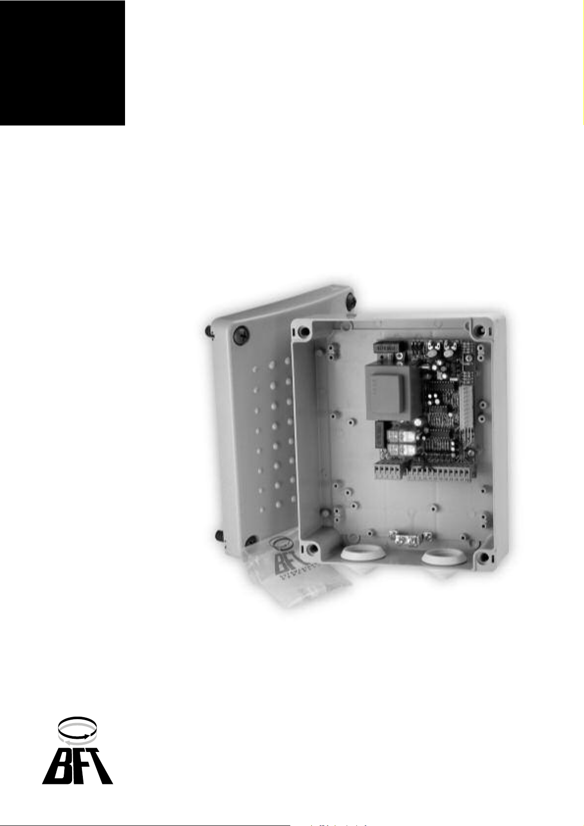
Control panel dimensions: ........................................................... See fig.1
Case protection: ................................................................................ IP54
Working temperature: ............................................................... -20 +55 °C
(*) Special voltages on request.
4) TERMINAL BOARD CONNECTIONS (Fig.2)
Keep the low voltage connections definitely separated from the power
supply connections.
M1A
1-2 Power supply 230V +/- 10% 50/60 Hz (Neutral wire to terminal 1).
3-4-5 M motor connection (terminal 4 common wire, terminals 3-5 motor
and capacitor operation).
1-4 Blinker connection 230V and Electric lock 230V mod. EBP.
M1B
7-8 Open-close push button and key selector (N.O.).
7-9 Stop button (N.O.). If not used, leave jumped.
7-10 Photocell or pneumatic edge input (N.C.). If not used, leave bridged.
7-11 Opening limit switch (N.C.). If not used, leave jumped.
7-12 Closing limit switch (N.C.). If not used, leave jumped.
13-14 24 Vac power supply output for photocell and additional devices.
15-16 Second radio channel output of the double-channel receiver board (N.O.)
17-18 Antenna input for radio-receiver board (18 braid - 17 signal).
CON1Radio-receiver board connector, 1-2 channels.
Fig.7 shows a general wiring diagram.
5) LED (Fig.3)
The MIZAR 6 control unit is provided with a series of self-diagnosis leds
which control all the functions.
The functions of the LEDs are the following:
(LD1 on - LD2 off) - Gate opening.
(LD1 off - LD2 off) - Gate stop.
(LD1 on - LD2 on) - Gate closing.
LD3 Start - goes on when a start command is given.
LD4 Closing limit switch - goes off when the closing limit switch is operated.
LD5 Opening limit switch - goes off when the opening limit switch is
operated.
LD6 Photocell - goes off when the photocells are not aligned or in the
presence of obstacles.
LD7 Stop - goes off when a stop command is given.
6) FUNCTIONING LOGIC
6.1) 4-step logic: (Dip-Fix IBL ON)
The following actions take place after a start command:
closed gate: ..................................................................................... opens
opening: ......................... stops and operates the TCA (Dip-Fix TCA ON)
open gate: ........................................................................................ closes
closing: ................................ stops (stops and does not operate the TCA)
after the stop: ................................................................................... opens
With Dip-Fix IBL ON, any start command given during opening has no effect.
6.2) 2-step logic: (on request)
The following actions take place after a start command:
closed gate: ...................................................................................... opens
opening: .......................... stops and operated the TCA (Dip-Fix TCA ON)
open gate: ......................................................................................... closes
closing: .............................................................................................. opens
after the stop: .................................................................................... opens
7) DIP-FIX SELECTION (Fig.3)
TCA Automatic closing time TCA.
ON: Automatic closing on.
OFF: Automatic closing off.
IBL Blocks impulses.
ON: START commands are not accepted during the opening phase.
OFF: START commands are accepted during the opening phase.
FCH Photocells.
ON: Photocells are only active in the closing phase. If an object is detected
by the photocells during the closing phase, the gate reverses the current
movement.
OFF: Photocells are active both in the closing and opening phase. If an
object is detected by the photocells on closing or opening, the gate stops;
once the object has been removed, the gate opens.
8) TRIMMER ADJUSTMENT (Fig.3)
TCA (Dip-Fix TCA ON)
It is used to set the automatic closing time, after which the gate closes
 Loading...