


Funlock 004D

Retyped by Mastersewusa.co
m
Important
Dear customer
Congratulations on your choice!
Your Bernette Funlock 004D/004 is made to the highest standards. It will cut, sew and neaten for you in one smooth
operation giving a professional look to anything you make.
The 4 thread Bernette Funlock is particularly suited to sewing stretch fabrics. Let your wardrobe and home benefit
from the Bernette’s superb sewing qualities. Our comprehensive Instruction Manual introduces you step by step to
the joys of overlocking and also gives you some useful sewing tips.
We wish you many happy hours of overlocking pleasure.
Safety Regulations
The following safety regulations must be observed without fail: It is important to pay attention to the needle and knife
while sewing as these are potential sources of injury to fingers. Movements within the area of the needle, knife or
looper such as threading, changing needles or presser feet, or raising the knife, may only be done with the machine
switched off (power switch at “O”). When cleaning or lubricating the machine replacing the bulb or when sewing is
finished, machine should be disconnected from the electricity supply. All repair work, especially electrical repairs
(e.g. renewing the cable connection out by one of our authorized service agencies.
Please note:
Funlock 004 is not equipped with differential feed. All points relating exclusively to Funlock 004D are marked with
the symbol. ✱
1

Retyped by Mastersewusa.co
m
Contents
Safety regulations 1
Contents 2
Details of the machine 3
● Accessories 4
Preparing the machine 5
● Foot control 5
● Assembling the thread stand 5
● Thread, cones, spools 6
Using the machine 7
● Main switch 7
● Handwheel 7
● Looper cover, cloth plate 7
● Presser foot lifter 8
● Changing the presser foot 8
● Inserting the needles 9
● Raising the upper knife 9
Threading 10
● Preparations 10
● Upper and lower looper 11/12
● Right-hand and left-hand needle 13/14
Threading/trial sewing 15
● 3 thread Overlock 15
● Sewing test/tension 15/16
● Adjusting tension 17
Adjustments and settings 18
● Stitch length 18
● Cutting width 18
● Differential feed ✱ 19/20
● Gathering ✻ 20
Setting/Practical sewing 21
● Presser foot pressure 21
● Roll hemming 22
● Sewing in tape 23
● Thread breakage, unpicking seams 23
Maintenance 24
● Changing knifes and light bulb 24
● Cleaning and lubricating 24
Trouble shooting guide 25
Technical data 26
2
Retyped by Mastersewusa.co
m
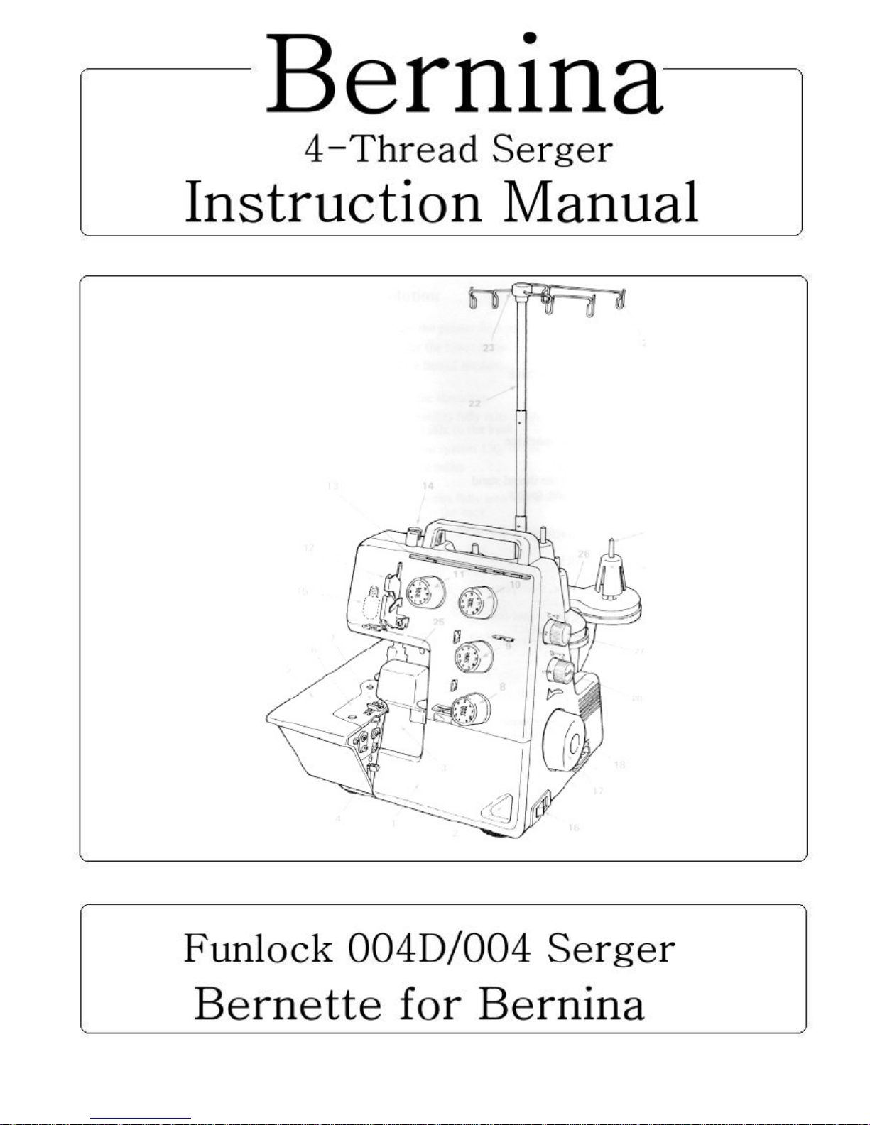
Details of the machine
Details of the machine
1. Looper cover
2. Looper cover opening indent
3. Knife guard
4. Cloth plate opening lever
5. Cloth plate
6. Stitch plate
7. Presser foot
8. Lower looper thread tension dial
9. Upper looper thread tension dial
10. Right needle thread tension dial
11. Left needle thread tension dial
12. Thread take-up cover
13. Thread guide plate
14. Presser foot adjusting screw
15. Sewing light
16. Power/light switch
17. Handwheel
18. Machine socket
19. Thread stand
20. Anti-vibration cone
21. Spool holder pin
22. Retractable support rod
23. Thread guide
24. Open thread guide
25. Presser foot lifter
26. Foam pad
27. Stitch length adjustment knob
28. Differential feed adjustment knob
3
21
20
19
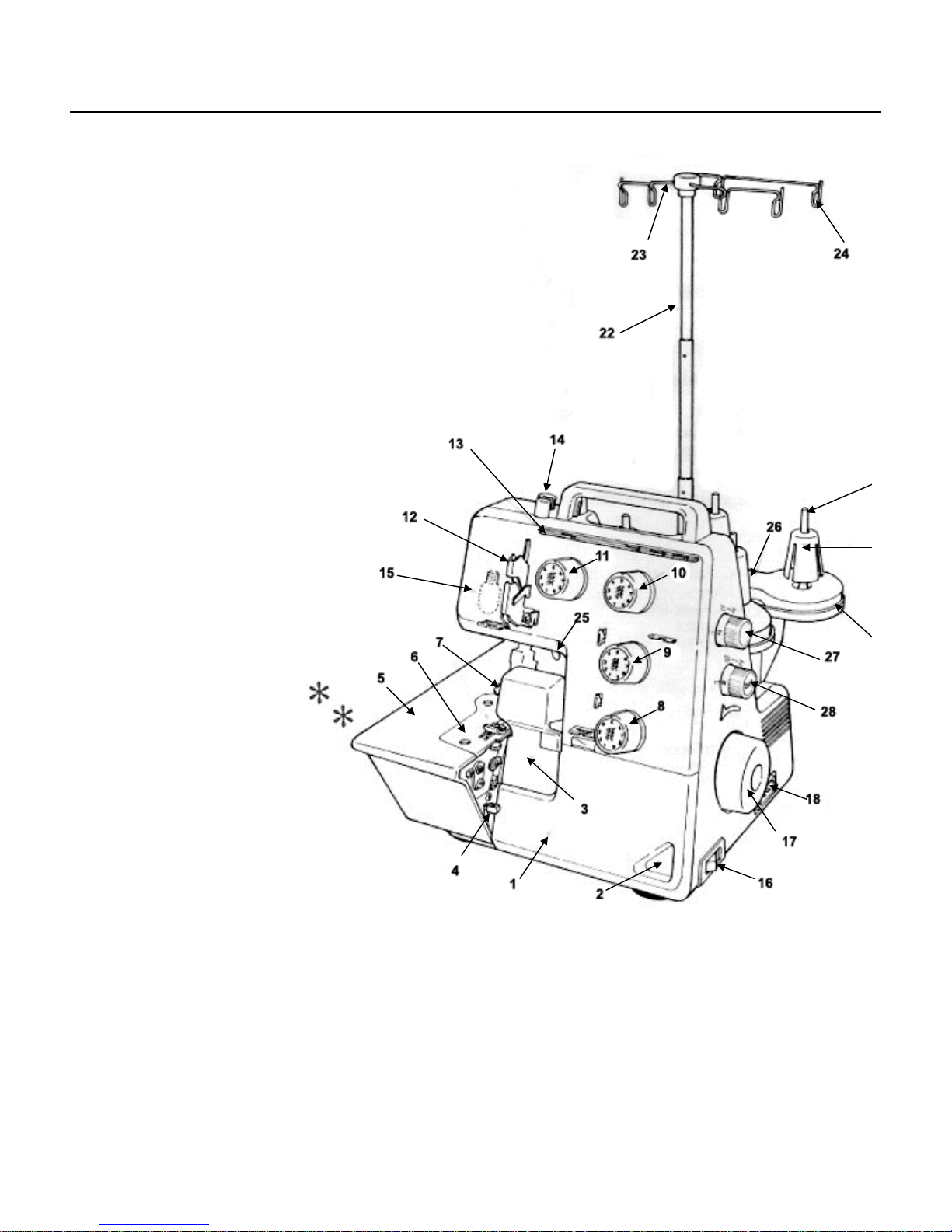
Details of the machine
View with looper cover open
1. Upper looper
2. Upper knife
3. Lower knife
4. Selection lever for overlocking or roll hemming
5. Lower looper
6. Lower knife setscrew
View with cloth plate open
1. Cutting with adjustment knob
2. Stitch length adjustment knob (004)
Accessories
1. Electronic foot control
2. Lower knife
3. Net
4. Spool caps
5. Tweezers
6. Cleaning brush
7. Looper threader
8. Needle threader
9. Set of household needles
10. Small screwdriver
11. Large screwdriver
12. Oiler
13. Accessory bag
14. Dust cover
4
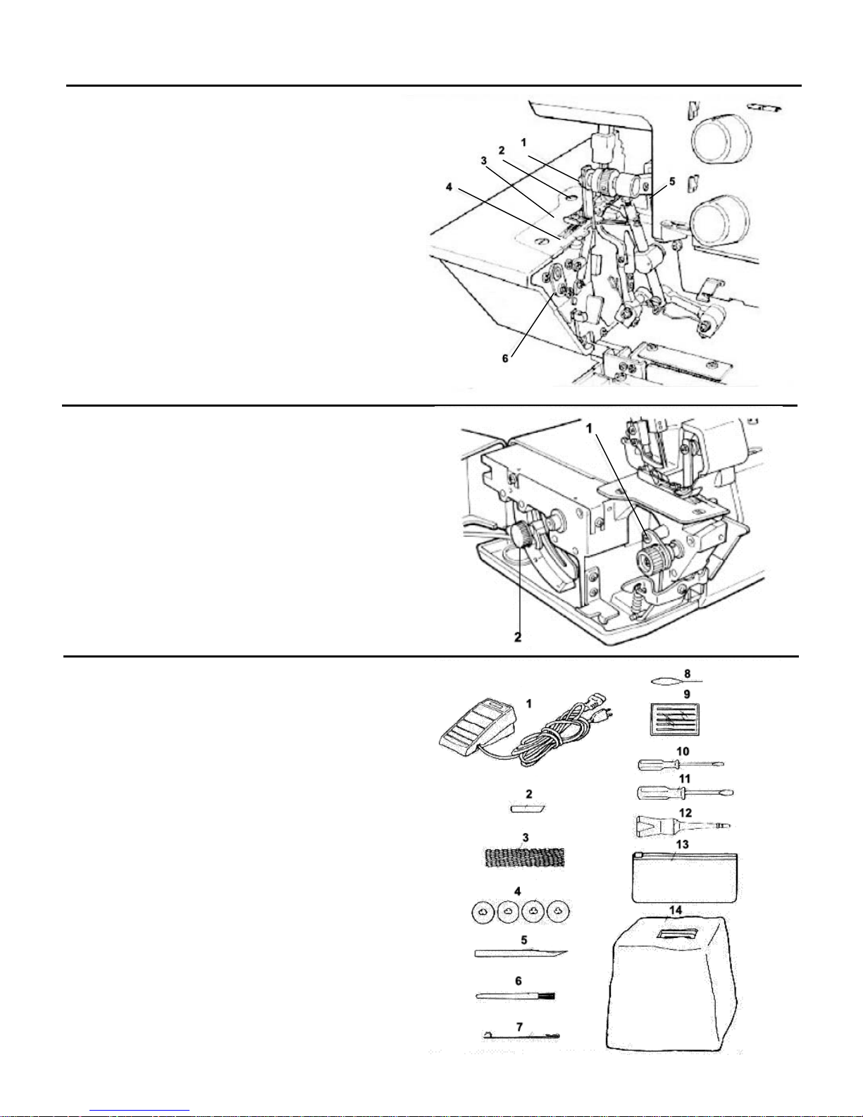
Preparing the machine
Attaching the foot control
Plug foot control into machine socket (A) and then into main
socket (B). The foot control regulates the sewing speed. The
sewing speed can be adjusted by increasing or decreasing the
pressure on the foot control.
Thread guide
Raise, the support rod fully, turning slightly until the
positioning catches engage (C). Position the thread guide on
the thread stand so that the arrow is to the front (D).
Thread Stand
Attach the separately packed spool holder to the fixed spool
holder.
5
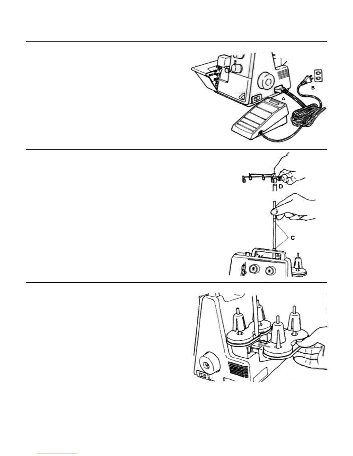
Preparing the machine
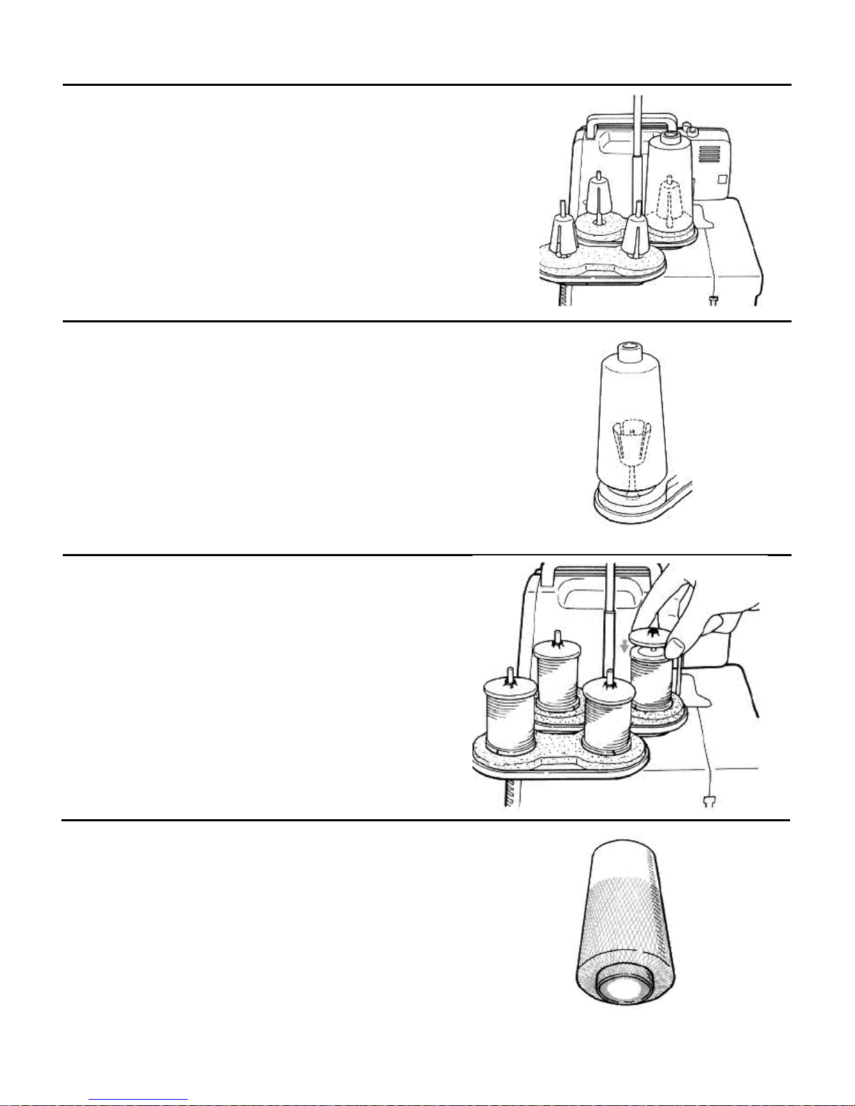
Thread cones/spools
The anti-vibration cone should be used with the wider edge
at the bottom on the spool holder pin when sewing with
cones.
Large spools
If large industrial spools are used, position the anti-vibration
cone upside down on the spool holder pin, i.e. with the wider
edge at the top.
Household spools
Remove the anti-vibration cones. Place spools on spool
holder pins and push the spool capon with the rounded side
downwards.
Thread net
If threading slip and get twisted, cover the spools of upper
and lower looper with the nets supplies in the accessory bag.
6
Using the machine
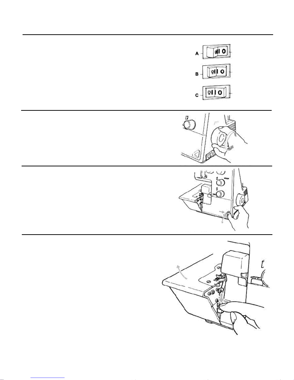
Power/light switch
The power/light switch is conveniently placed on the handwheel side of the machine in front of the socket.
• Off (A)
• On without light (B)
• On with light (C)
Handwheel
The handwheel turns forward, i.e. in the same direction as on
a household sewing machine.
Looper cover
To open press to the right with your thumb in the indent
provided and tilt the cover towards you. To close, push it up
and press lightly to the right. The cover engages
automatically.
Cloth plate
The cloth plate opens automatically by pushing the lever
downwards. To close the cloth plate, push it towards the
machine and press gently until the cover engages.
7
Using the machine
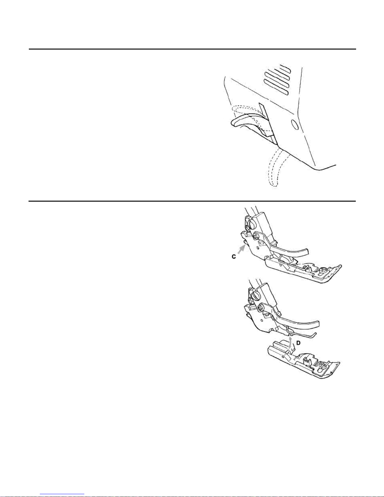
Two-step presser foot lifter
To raise the presser foot, raise the presser foot lever on the
rear of the machine, until it engages (A). It can be raised
again to maximum height and held in this position to provide
more space between presser foot and stitch plate (B).
Changing the presser foot
• Turn power switch to “O”
• Raise the presser foot
• Turn handwheel towards you until needles are fully
raised.
Press the catch (C) to release the presser foot from the
clamp. Raise the presser foot to the highest position (B)
and remove the presser foot to the left. To attach the
presser foot, place it under the shaft. The groove in the
shaft should line up exactly with the presser foot pin
(D). Lower the shank and the presser foot will engage
automatically.
8
 Loading...