


ACTIVA 135 S

See appendix for differences in the
030529.52.04_0303_a135 a145_EN
activa 135 S Patchwork Edition

In choosing BERNINA, you are assured of years of rewarding sewing. For over 100 years my family
030529.52.04_0303_a135 a145_EN
has concentrated on providing complete satisfaction to our customers. And it is my personal wish to
continue this tradition of offering you Swiss precision engineering combined with state of the art
”Welcome to
the BERNINA
family”
H.P. Ueltschi
Owner BERNINA
Sewing Machine Company
technology and an after sales service second to none.
The new BERNINA activa 135 S and 145 S are characterized by a youthful appeal which is combined
with a range of added value features to give you, dear Customer, more sewing pleasure than ever
before.
Enjoy modern, creative sewing with BERNINA: our wide range of accessories as well as
our sewing publications brimming with imaginative ideas and practical tips all add to the joy of
sewing BERNINA style.
Any questions you have will be dealt with courteously and efficiently by our highly
trained BERNINA dealers, who will also be glad to service your sewing computer for you.
•
Fritz Gegauf Ltd.
BERNINA Sewing Machines •CH-8266 Steckborn/Switzerland
2
030529.52.04_0303_a135 a145_EN
IMPORTANT SAFETY INSTRUCTIONS
When using an electrical machine, basic safety precautions should
always be followed, including the following.
Read all instructions before using this sewing computer.
When the sewing computer is not in use, it should be
disconnected from the electricity supply by removing the plug
from the outlet.
DANGER
To reduce the risk of electric shock:
1. A sewing computer should never be left unattended when
plugged in.
2. Always unplug the sewing computer from the electric outlet
immediately after using and before cleaning.
3. Always unplug before replacing light bulb. Replace the bulb
with the same type rated 12 volts/5 watts.
WARNING
To reduce the risk of burns, fire, electric shock or injury
to persons:
1. Do not allow to be used as a toy.
Close attention is necessary when the sewing computer is
used by or near children and infirm persons.
2. Use this sewing computer only for its intended use as
described in this manual. Use only attachments recommended
by the manufacturer as contained in this manual.
3. Never operate this sewing computer if
•
it has a damaged cord or plug
•
it is not working properly
•
it has been dropped or damaged
•
it has fallen into water
Return the sewing computer to the nearest authorized
BERNINA dealer or service center for examination, repair,
electrical or mechanical adjustment.
4. Never operate the computer with any air openings blocked.
Keep ventilation openings of the sewing computer and foot
control free from accumulation of lint, dust and loose cloth.
5. Keep fingers away from all moving parts. Special care is
required around the sewing needle.

3Safety instructions
030529.52.04_0303_a135 a145_EN
6. Always use the BERNINA original needle plate. The wrong plate
can cause the needle to break.
7. Do not use bent needles.
8. Do not pull or push fabric while stitching. It may deflect the
needle causing it to break.
9. Turn power switch to «0» when making any adjustments
in the needle area, such as threading or changing the needle,
threading the bobbin or changing the presser foot.
10. Always unplug the sewing computer from the electrical outlet
when removing covers, lubricating or when making any other
user servicing adjustments mentioned in this instruction manual.
11. Never drop or insert any object into any opening.
12. Do not use outdoors.
13. Do not operate where aerosol (spray) products are being used or
where oxygen is being administered.
14. Before disconnecting, turn all controls to the off («0») position
then remove the plug from the outlet.
15. Do not unplug by pulling on the cord but grasp the plug.
16. No responsibility will be taken for any possible damage as the
result of misuse of the sewing computer.
17. This sewing computer is provided with double insulation.
Use only identical replacement parts. See instructions for
Servicing of double-insulated machines.
SERVICING DOUBLEINSULATED PRODUCTS
In a double-insulated product, two systems of insulation are provided instead of grounding. No grounding means is provided on a
double-insulated product nor should a means for grounding be
added to the product. Servicing a double-insulated product requires extreme care and knowledge of the system and should only be
done by qualified service personnel. Replacement parts for a
double-insulated product must be identical to those parts in the
product. A double insulated product is marked with the words
«DOUBLE INSULATION» or «DOUBLE INSULATED».
The symbol may also be marked on the product.
This sewing computer is intended for household use only.
SAVE THESE INSTRUCTIONS!
Details4
030529.52.04_0303_a135 a145_EN
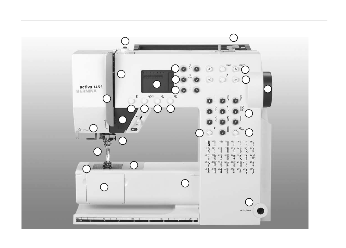
Details of the sewing computer
11
14
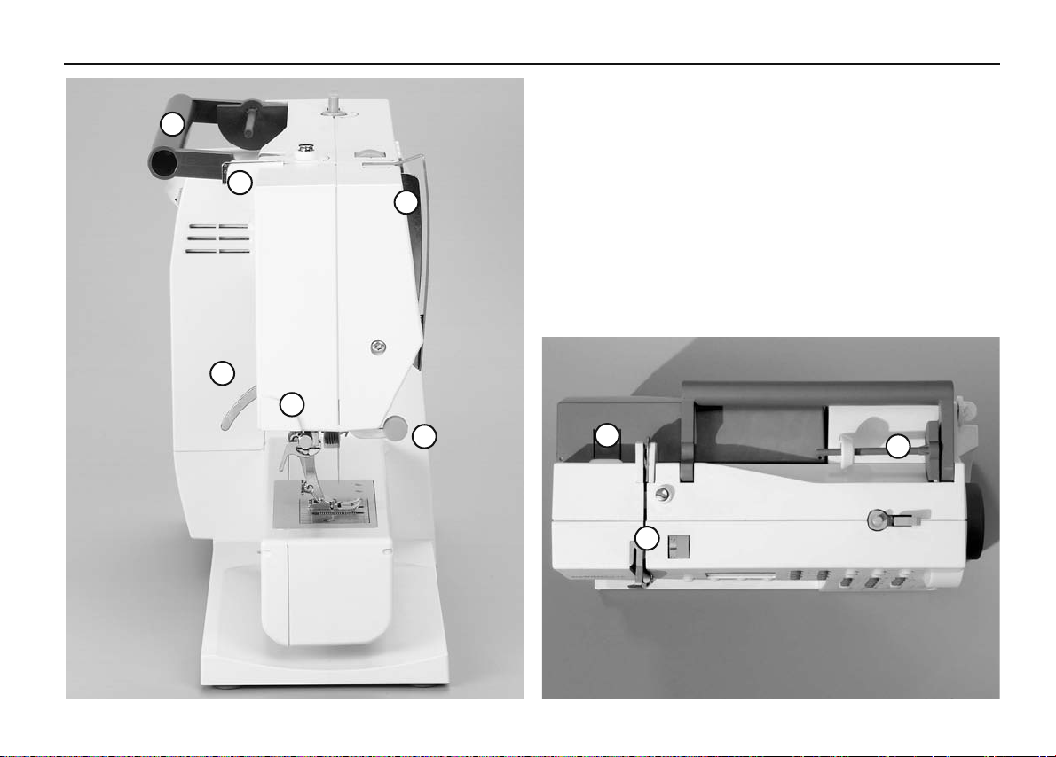
Front view
9
13
8
19 20 21
18
12
7
6
5
2
1
3
15
16
17
25
4
22
23
27
24
26
28
11
030529.52.04_0303_a135 a145_EN
Details
5
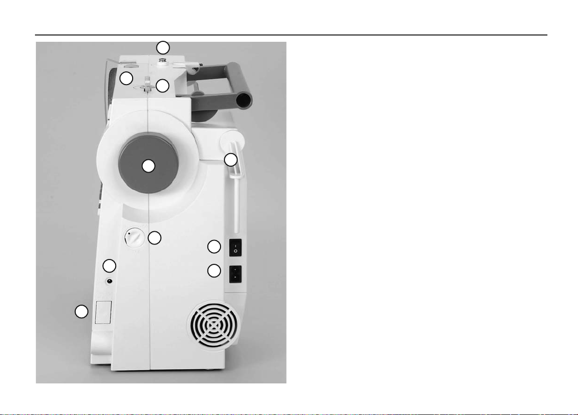
Right end
32
33
10
27
29
14
30
31
34
1 Bobbin cover
2 Stitch plate
3 Attachment base for
special accessories
4 Sewing table socket
5 Presser foot
6 Needle clamp with
fixation screw
7 Thread guide
8 Thread take up cover
9 Thread path
10 Thread tension
adjustment
11 Bobbin pre-tension
12 Reverse button/quick and
continuous
13 Screen
14 Bobbin winder with
on/off switch and thread
cutter
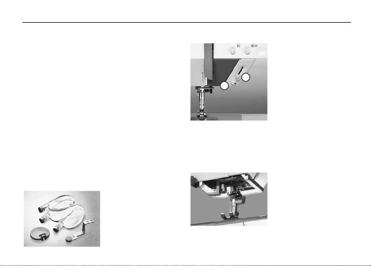
15 Stitch width button
16 Needle position button
17 Stitch length button
18 Needle stop up/down
19 1/2 speed
20 Pattern end
21 Mirror image
22 mem (memory) button
23 Alphabet buttons
24 Stitch selection buttons
25 #-button
26 clr/del-button
27 Handwheel
28 FHS connection
29 Balance adjustment knob
30 Power switch on/off
31 Power plug socket
32 Drop feed-dog
33 Foot control socket
34 Spool pin (vertical,
collapsible)
Details6
030529.52.04_0303_a135 a145_EN
43
42
40
36
45
37
3
39
2
4
Back view
Details
030529.52.04_0303_a135 a145_EN
7
35
36
42
37
38
46
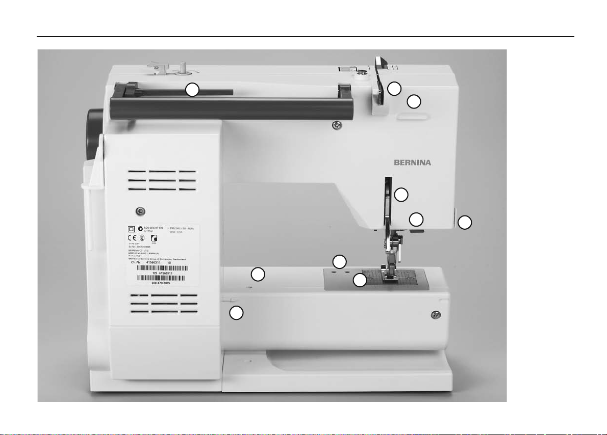
35 Carrying handle
36 Presser foot lifter
(manual)
37 Thread cutter
38 Thread take up
39 Darning ring connection
40 Accessory box connection
41 Thread tension disc
42 Rear thread guide
43 Horizontal spool pin
44 Accessory box catch
44
41
45 Needle Threader
46 Lens holder
43
Left end
Sewing computer with Accessory box
Accessory box
8 Setting up the sewing computer
030529.52.04_0303_a135 a145_EN
Accessories
•
foot control
•
instruction manual
•
power cable
•
warranty card
•
Accessory box
•
presser foot lifter
Standard accessories*:
4 bobbins (+ 1 in the capsule
in the sewing computer)
Selection of 130/705H needles
Seam ripper
Screwdriver
Angle key Torx
Screwdriver Torx
Lint brush
Seam guide
Compensating plate
3 spool discs
Foam pad
Oiler
Fabric cover
•
protects from dust and dirt
•
compartment for accessories
Lens Set: **
We recommend the use of the
BERNINA Lens Set for more
comfort when sewing.
Caution!
To avoid injury always attach
the protective cover of the
magnifying glass holder
when the magnifying glass is
not in use.
Start-stop-unit**
B
A
* can vary from country to country;
see presser foot selection p. 33
** available as a special accessory
Please refer to the safety
instructions!
With the Start-stop-unit (SSU)
the start-stop-function can be
controlled by hand.
•
press start-stop-button A =
stitching starts
•
with the speed regulator B
the sewing speed can be
regulated by hand
•
to interrupt or stop sewing =
press start-stop-button A
again
Note:
If the foot control is connected with the sewing machine,
the Start-stop-unit is out
functions.
CFL **
Contrary to an ordinary bulb, the CFL
sewing light has a better illumination
and a longer life.
Caution:
Please note that a defective CFL
sewing light must ONLY be replaced
by an authorized technician. The
sewing computer must be brought
to an authorized BERNINA dealer!
Accessory box
030529.52.04_0303_a135 a145_EN
Setting up the sewing computer 9
D
F
G
A
H
E
B
C
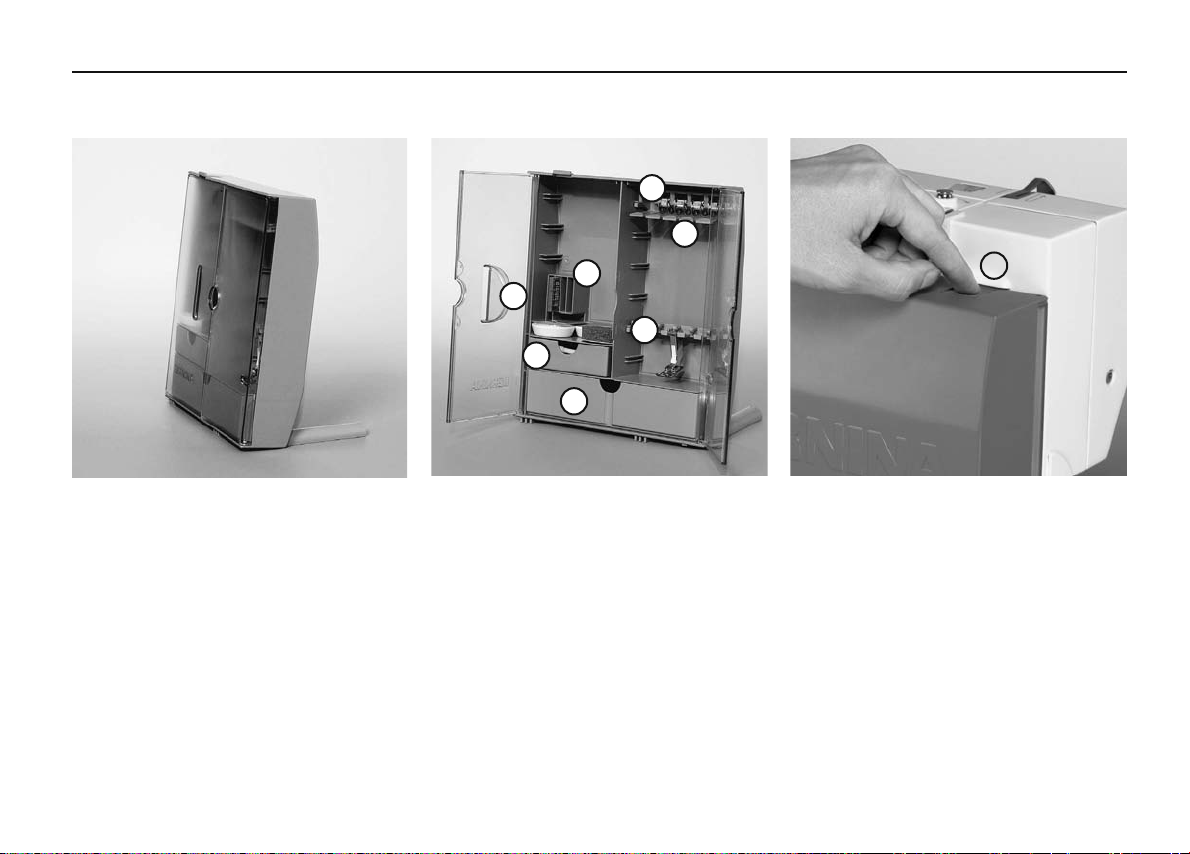
Free standing accessory box
•
pull both feet out until they click into
place
•
stand box in chosen position
Storing accessories
Standard accessories are supplied in a
plastic bag.
The box is equipped with one small and
one large drawer (B and C) as well as compartments for bobbin holders D and presser
feet E. (Additional compartments and
drawers are available as optional extras.)
•
push the bobbins into the compartments
provided
•
to remove a bobbin, press the compartment holder F lightly
•
insert the presser feet into the slot E
•
the needle selection box can be stored in
compartment G
Attaching the accessory box to the
sewing computer
•
close the doors
•
push feet back into position
•
attach the box to the sewing computer
(catch A must engage); inserting
the presser foot lifter into the opening H
Note: first lower the presser foot lifter!
Removing the accessory box
•
press catch A on the top of the box
•
remove box to the rear
Available as a special accessory
Setting up the sewing computer10
030529.52.04_0303_a135 a145_EN
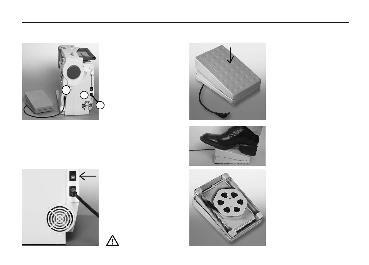
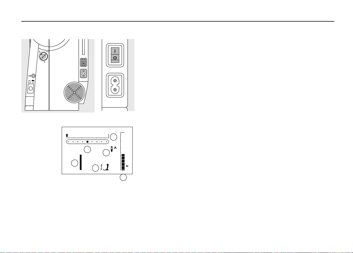
Power cable
C
Power switch
Foot control
The power cable
•
plug A into sewing computer
•
plug B into wall socket
Foot control cable
•
plug C into sewing computer
Important! (USA/Canada only)
A
This sewing computer has a
polarized plug (one blade
B
wider than the other). To reduce the risk of electric shock,
this plug is intended to fit in a
polarized outlet only one way.
If the plug does not fit fully in
the outlet, reverse the plug.
If it still does not fit, contact a
qualified electrican to install
the proper outlet. Do not
modify the plug in any way.
The switch is on the handwheel
side of the computer
1 the computer is switched on
0 the computer is switched off
The sewing light is switched on
and off with the power switch.
The foot control regulates the
sewing speed
Sewing speed is adjusted by
applying more or less pressure
to the foot control.
Important! (USA/Canada only)
Use only foot controller type
SR-1 with sewing computers
activa 135 S/145 S.
Self storing cord
•
wind the cord on the reel
•
insert the plug into the groove provided
When sewing
•
unwind the cable
Refer to the safety
instruction!
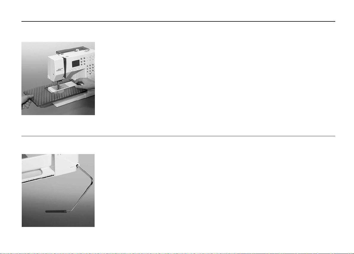
Sewing table
030529.52.04_0303_a135 a145_EN
11Setting up the sewing computer
Increases the sewing surface.
To attach
•
raise the needle and presser
foot
•
place the table over the free
arm and press firmly so that it
To remove
•
raise the needle and presser
foot
•
pull the table out of the
fixing cam
•
pull in horizontal position to
the left
Seam guide
•
•
engages on the fixing cam
Scale
•
«0» corresponds to the centre
needle position
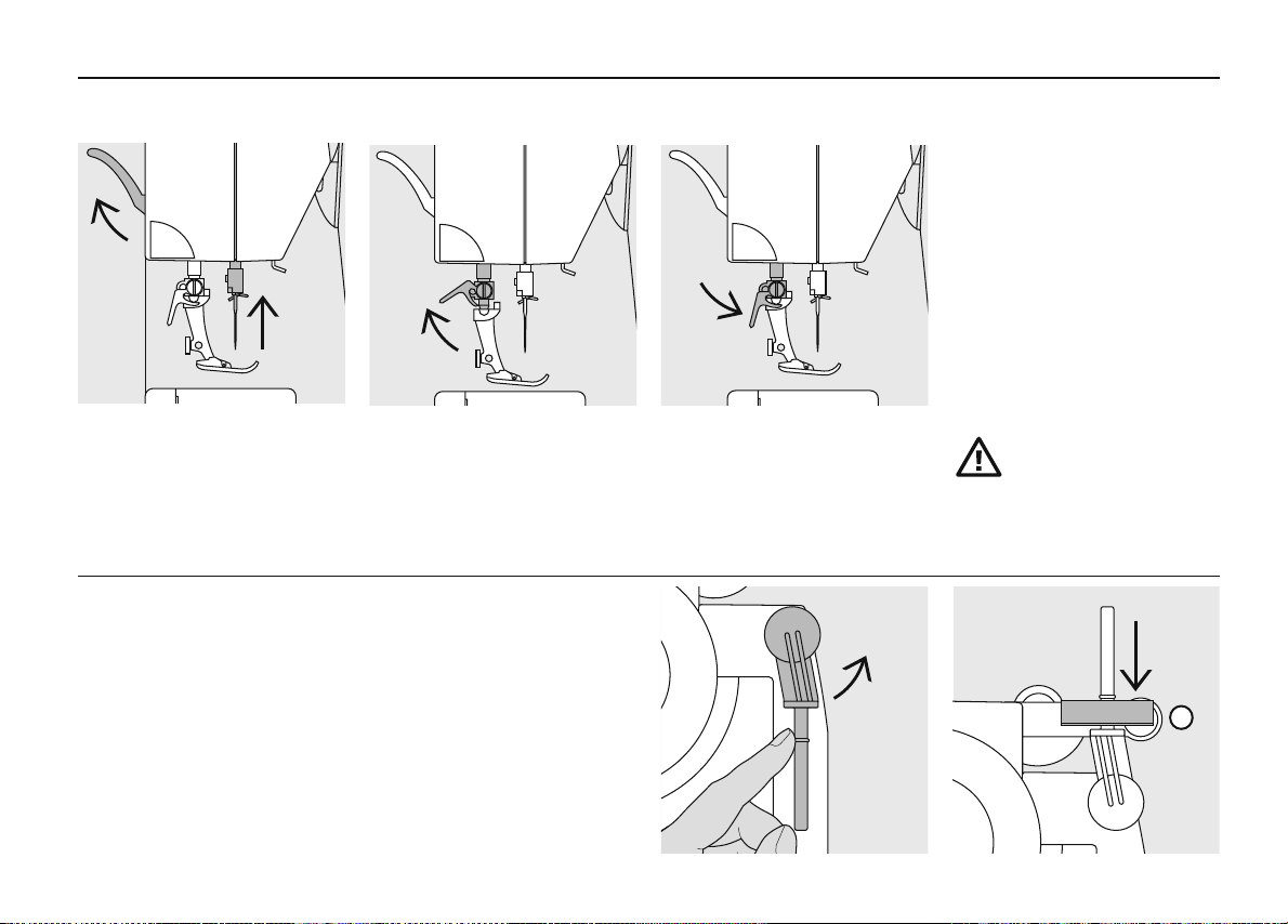
Free-Hand-System (FHS) presser foot lifter* (knee-operated)
Attaching the presser foot
lifter
Insert into the opening in the
base plate: you should be able
to operate the lifter with your
knee in your normal sitting
position.
Note:
Your dealer can adjust it if
necessary.
The presser foot lifter raises
and lowers the presser foot
•
push to the right
•
the presser foot is raised
•
the feed-dog is lowered
simultaneously
•
the feed-dog is raised as soon
as the first stitch is sewn
* Special accessory can vary from
insert into the groove (underside of table) from the right or
left
it can be freely adjusted over
the whole width of the table
Note: Remove the presser
foot when attaching the seam
guide!
country to country
Setting up the sewing computer12
030529.52.04_0303_a135 a145_EN
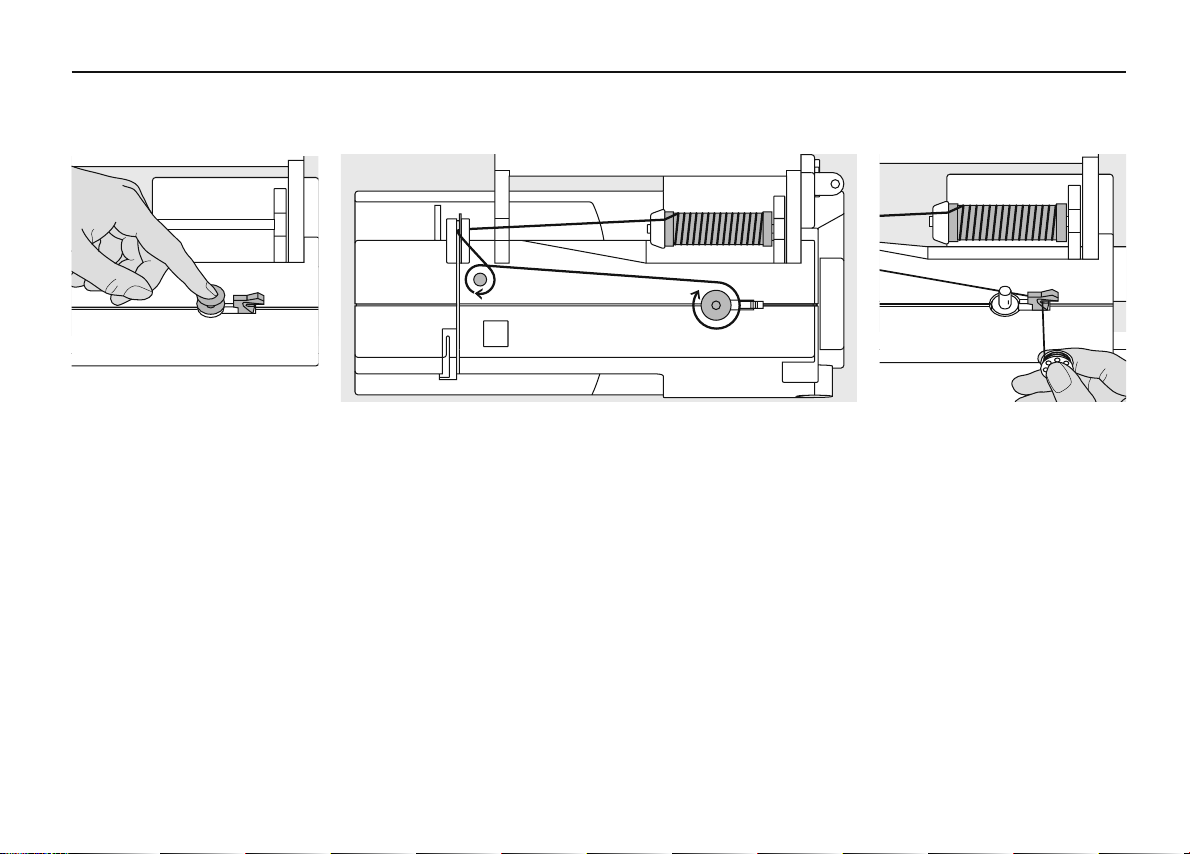
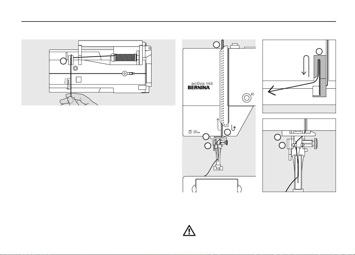
Winding the bobbin
Winding the bobbin
•
turn power switch on
•
place empty bobbin on
spindle
Note:
When winding the bobbin
on the vertical spool holder
(p. 15), it may be necessary to
adjust the speed.
•
following the direction of the arrow take thread through the rear
guide and round the pre-tension stud
•
wind it several times round the empty bobbin
•
press the engaging lever against the bobbin
•
press the foot control
•
the motor will stop automatically when the bobbin is full
•
remove the bobbin
Thread cutter
•
cut the thread on the thread
cutter
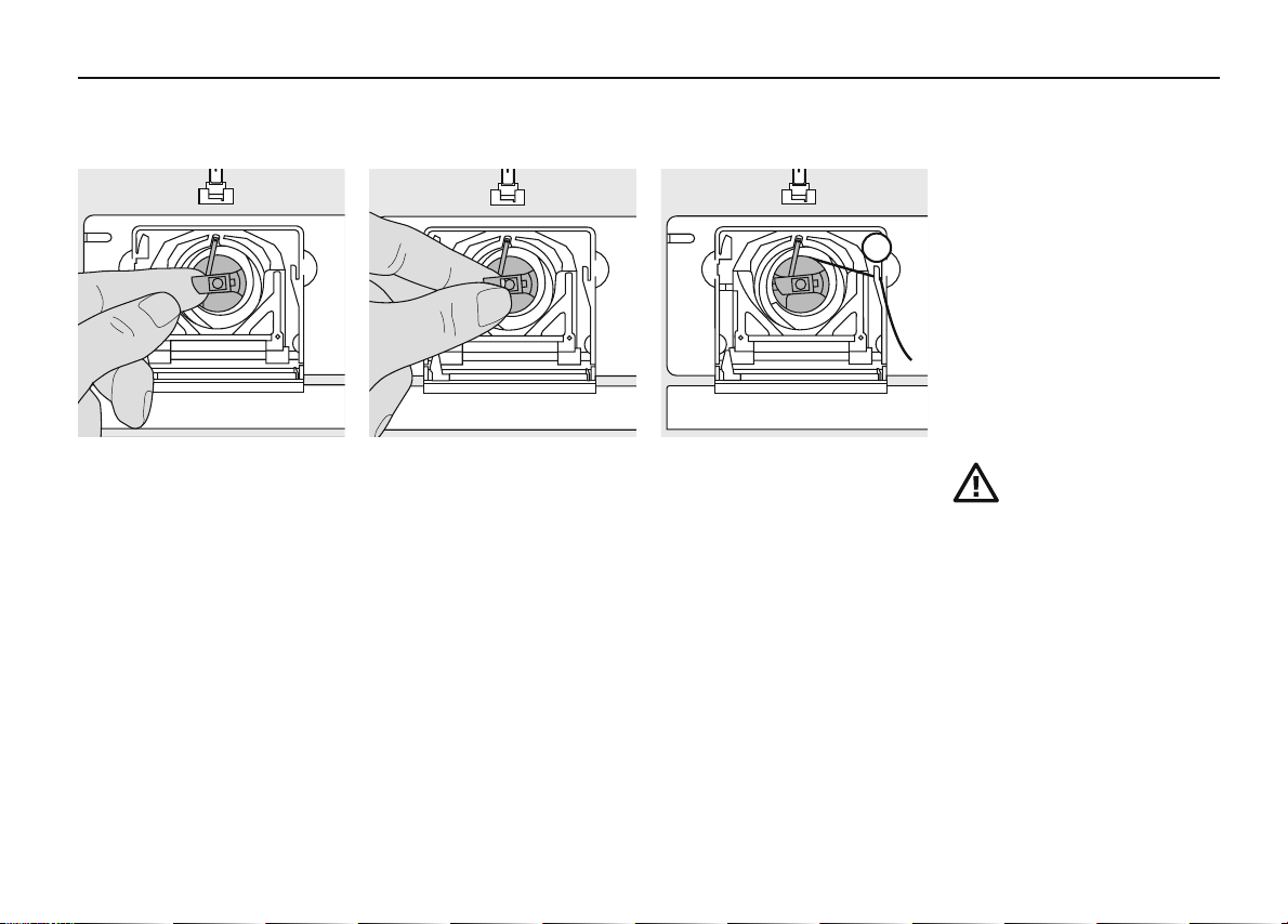
Bobbin case
030529.52.04_0303_a135 a145_EN
13Setting up the sewing computer
A
To remove the bobbin case
•
raise the needle
•
turn power switch to «0»
•
open the bobbin cover
•
grasp the latch of the bobbin
case
•
remove case
To insert the bobbin case
•
hold the bobbin case latch
•
the finger on the case should
point upwards
•
insert so that it clicks into
place
Bobbin thread cutter
•
insert the bobbin case
•
take the thread over cutter A
•
thread is cut
•
close the bobbin cover
Note:
The bobbin thread does not
have to be brought up as
the loose end is just the right
length to start sewing.
Refer to the safety
instruction!
Setting up the sewing computer14
030529.52.04_0303_a135 a145_EN
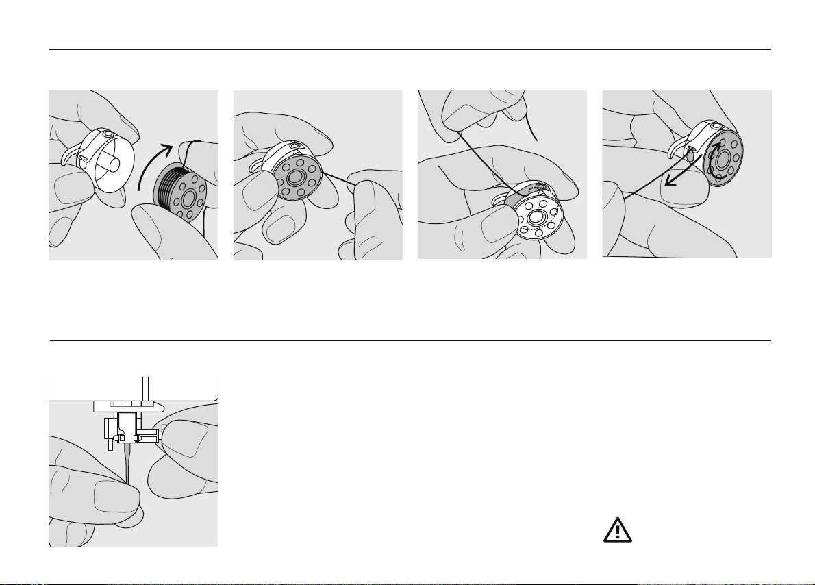
Inserting the bobbin
Insert the bobbin
Insert the bobbin so that the
thread runs clockwise.
Changing the needle
Pull the thread counter clockwise into the slot.
Removing the needle
•
raise the needle
•
turn power switch to «0»
•
lower the presser foot
•
loosen the needle clamp screw
•
pull the needle down to remove
Inserting the needle
•
flat side of needle to the back
•
insert the needle as far as it will go
•
tighten the needle clamp screw
Pull the thread to the left
under the spring until ...
... it lies in the T-shaped slit at
the end of the spring.
The bobbin must turn clockwise when thread is pulled.
Refer to the safety
instruction!
Changing the presser foot
030529.52.04_0303_a135 a145_EN
15Setting up the sewing computer
Presser foot with shank
•
raise the needle and
•
presser foot
•
turn power switch to «0»
Supplementary spool pin
Collapsible vertical spool pin
•
found on the back of the sewing computer
behind the handwheel
•
essential aid for sewing with more than one thread, i.e. double
needle work
•
raise the pin until it clicks into its vertical position
•
when using large reels, add the foam pad A for stability
•
raise the clamping lever
•
remove the presser foot
Attaching the presser foot
•
guide the foot upwards
•
over the cone
•
press the clamping lever
down
Refer to the safety
instruction!
A
Setting up the sewing computer16
030529.52.04_0303_a135 a145_EN
Threading the upper thread
A
•
raise the needle and presser foot
•
turn the power switch to «0»
•
place spool on pin and attach the appropriate
spool disc – diameter of spool = disc size
•
take thread through rear guide A
•
then into slit of upper thread tension
•
pull thread down to the right of the take-up cover to B
•
then up to the left of the cover to C
•
and down through guides D and E
C
C
C
S
D
E
B
D
E
Refer to the safety
instruction!
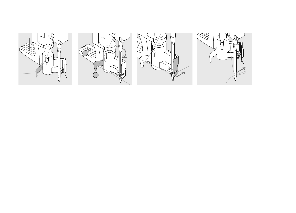
Needle Threader
030529.52.04_0303_a135 a145_EN
17Needle Threader
A
B
Thread in hook
· lower the presser foot
· lay the thread behind
hook B and hold lightly
Lever down
· press lever A down and
simultaneously guide the
thread around hook B to
the right to the needle
Thread in front of needle
· put the thread from the
front into the guide until
it catches in the hook
Release the lever and thread
· let go of lever A and
thread
Setting up the sewing computer18
030529.52.04_0303_a135 a145_EN
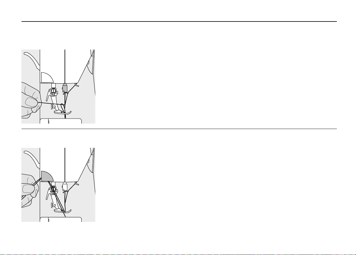
Bringing up the lower thread
•
hold the upper thread
•
sew one stitch
•
pull the upper thread until the bobbin thread appears
in the stitch plate hole
•
pull bobbin thread out of the hole and insert both
threads through the slit in the presser foot towards the back
•
pull threads over the cutter
Thread cutter
•
pull both threads from front to back over the
cutter
•
the threads release as soon as the first stitch is
sewn
Note:
The bobbin thread must be
brought up through the stitch
plate for certain types of
work. The length of thread
is sufficient for most normal
work if the lower thread
cutter has been used.
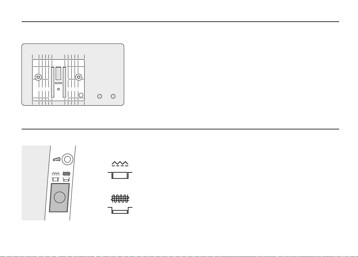
Stitch plate
030529.52.04_0303_a135 a145_EN
1
15/
1
/
8
4
Feed-dog
19Setting up the sewing computer
Stitch plate markings
•
5
/
4
1
/
8
the stitch plate is marked with seam guide lines in mm and inches
•
the millimetre markings are at the front
•
the inch markings are at the back
•
the measurements show the distance (with needle position centre) from
needle to line
•
10 201020
lines are provided to the right and left of the needle
•
they are very useful guide lines for precise seaming
•
the horizontal lines are useful for sewing corners, etc.
Button below the handwheel
Button flush with housing =
sewing position
Button depressed = feed-dog is lowered
•
for free-hand sewing (darning, embroidery, etc.)

Setting up the sewing computer20
3
5
030529.52.04_0303_a135 a145_EN
Thread tension
The basic setting
•
is indicated when the red line on the tension
adjustment wheel is in line with the marking A
•
A
the tension does not need adjusting for normal
The tension is factory set for the best results.
Metrosene 100/2 (Arova Mettler, Switzerland)
is used to set both the upper and lower thread
tension.
sewing work
•
for special sewing work, the tension can be
adjusted to suit the fabric
If other sewing or embroidery threads are used,
the tension may need adjusting to suit the fabric
and chosen stitch.
For example:
To reduce the tension
turn to between 3 and 1
To increase the tension
Metallic thread approx. 3 90
Tension Needle
turn to between 5 and 10
Monofilament approx. 2– 4 80
0
23451
5.5
1
2
3
4
5
0
General instructions
030529.52.04_0303_a135 a145_EN
3
5
6
21Operating instructions
Main switch to 1
•
the sewing sewing computer is ready to sew
The screen shows
1
1 stitch width basic setting blinks constantly
2 stitch length basic setting blinks constantly
4
3 needle position (9 positions)
4 needle stop up/down (generally up)
5 stitch number 1 (straight stitch)
6 presser foot number 1 indicator (recommended foot
2
for selected stitch)
 Loading...