Bendix SR-5 TRAILER SPRING BRK VALVE User Manual

®
SD-03-4516
Bendix® SR-5™ Trailer Spring Brake Valve
PRESSURE
PROTECTION
VALVE
|
1/4” NPT |
|
SERVICE |
SR-5™ VALVE |
RESERVOIR |
IDENTIFICATION |
(2) |
HOLE |
|
COVER* |
|
|
1/4” NPT |
|
|
|
|
TRAILER SUPPLY |
|
EXHAUST |
1/2” OR 3/4” NPT |
|
1/4” NPT TRAILER |
3/8” NPT |
SPRING BRAKE |
|
|
|
RESERVOIR |
||
|
SERVICE |
DELIVERY (4) |
|
|
|
|
|
||
|
|
|
|
|
FIGURE 1 |
SR-5™ TRAILER SPRING BRAKE VALVE |
|
|
|
|
*SHOWN WITH OPTIONAL ANTI-COMPOUNDING COVER |
|
|
|
DESCRIPTION
The SR-5™ valve is a reservoir-mounted trailer valve that can control up to four spring brake actuators during parking or emergency applications. It has the following capabilities:
•Automatically applies trailer spring brakes in the event of a breakaway or trailer supply line failure.
•Protects trailer reservoir(s) air pressure in the event of a breakaway or trailer supply line failure.
•Allows no automatic trailer spring brake application with air pressure loss in trailer reservoir(s).
•Allows the trailer spring brakes to be applied and released repeatedly with a failed trailer reservoir(s):
•Optional anti-compounding-prevents an overriding service brake signal while the trailer supply line is at atmospheric pressure.
•Does not allow service system charging if a failure occurs in the parking brake circuit.
PORTS
1 - 1/2" or 3/4" NPT Spring Brake Reservoir Mounting (SPR BK RES)
1 - 1/4"-18 NPT Trailer Supply (TRL SUP)
1 - 1/4"-18 NPT Trailer Service (TRL SER)
4 - 3/8"-18 NPT Delivery (DEL)
2 - 1/4"-18 Service Reservoir (SERV RES)
1 - Exhaust (EXH)
The SR-5™ valve appears very similar to the SR-2™ valve. Both valves consist of a die-cast aluminum body and cover, pressure protection valve, and reservoir-mounting nipple. However, Figure 1 notes the distinguishing characteristic of the SR-5™ valve–a hole drilled into the flat surface between the pressure protection valve and the body.
1

TRAILER SERVICE
SERVICE/SPRING
BRAKE
RESERVOIR
SERVICE/SPRING BRAKE
RESERVOIR
SERVICE
RELAY
VALVE
SR-5™
VALVE
TRAILER SUPPLY
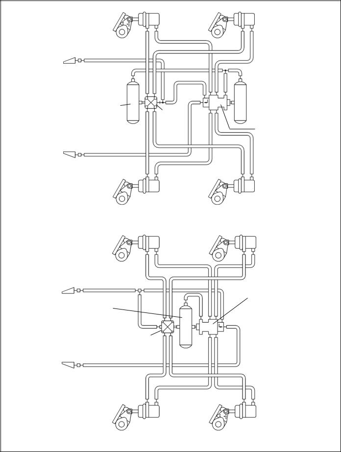
TWO-TANK SYSTEM
TRAILER SERVICE
SR-5™
SERVICE/SPRING BRAKE VALVE
RESERVOIR
SERVICE
RELAY
VALVE
TRAILER SUPPLY
ONE-TANK SYSTEM
FIGURE 2 TYPICAL SYSTEM SCHEMATICS WITH SR-5™ TRAILER SPRING BRAKE VALVE
2

TRAILER SERVICE
CHECK
VALVE
D
TRAILER SERVICE RES.
CHECK
VALVE PASSAGE A
B
SERVICE/SPRING
SERVICE BRAKE RESERVOIR
RELAY CONNECTION
VALVE
TRAILER SUPPLY
CONTROL PISTON
EXHAUST
DELIVERY
SPRING
BRAKE
CHAMBER
FIGURE 3 CHARGING BELOW 70 PSI
OPERATION
CHARGING BELOW 70 PSI (SEE FIGURE 3)
Air flows through the trailer supply line, enters the SR-5™ valve trailer supply port, and moves the control piston. The control piston contacts the control inlet/exhaust valve, sealing off the piston’s exhaust passage.
As piston travel continues, the control inlet valve opens. Air acting on the control piston also flows through passage A, unseating check valve B, and flowing past the open control
inlet valve. This air flows into the spring brake cavities, releasing the spring brakes.
CHARGING ABOVE 85 PSI (SEE FIGURE 4)
Air pressure acting on the control piston and flowing through passage A also acts on pressure protection valve C. At approximately 85 psi, valve C opens. This allows the air to flow past check valve D and charge the trailer reservoir(s). The trailer braking system is now in the normal run mode. Service braking occurs through the trailer service relay valve.
|
|
TRAILER SERVICE |
|
|
CHECK |
|
|
VALVE D |
|
TRAILER SERVICE RES. |
PRESSURE |
|
|
|
|
CHECK |
PROTECTION |
|
VALVE B |
VALVE C |
|
SERVICE/SPRING |
PASSAGE A |
|
BRAKE |
|
SERVICE |
RESERVOIR |
|
RELAY |
CONNECTION |
|
VALVE |
|
|
CONTROL PISTON
EXHAUST
DELIVERY
SPRING
BRAKE
CHAMBER
FIGURE 4 CHARGING ABOVE 85 PSI
3
 Loading...