


|
|
|
|
|
|
|
|
|
|
|
|
SD-03-4508 |
|
|
|
|
|
|
|
|
|
|
|
||
|
|
|
|
|
|
|
|
|
|
|
||
|
|
|
|
|
|
|
|
|
|
|
|
|
Bendix® SR-1™ Spring Brake Valve |
|
|
|
|
|
|
|
|
|
|||
|
|
|
|
|
|
|
|
|
|
|
||
|
|
|
|
|
|
|
|
COVER (13) |
PISTON |
|||
|
|
|
|
|
|
PISTON SPRING |
SPRINGS (14) |
|||||
|
|
|
|
|
|
|
|
|||||
|
|
|
|
(14) |
|
|
|
|
O-RING |
|||
|
|
|
|
|
PISTON (15) |
|
|
|
|
(LARGE) |
||
|
|
|
|
|
|
|
|
|
(18) |
|
||
|
|
|
|
PISTON O-RINGS |
|
|
|
|
|
|||
|
|
|
|
|
|
|
|
PISTON (17) |
||||
|
|
|
|
(16) |
|
|
|
|
||||
|
1/4 P.T. |
|
|
|
|
|
|
O-RING |
||||
|
|
|
|
VALVE (12) |
|
|
|
|
||||
|
|
|
|
|
|
|
|
(SMALL) (19) |
||||
|
RES. #1 |
|
|
VALVE SPRING (11) |
|
|
|
|
BODY |
|||
|
|
|
|
VALVE STOP (10) |
|
|
|
|
CHECK |
|||
|
1/4 P.T. |
|
|
|
|
|
|
VALVE(4) |
||||
|
|
|
|
|
|
|
|
|
|
|||
|
1/4 P.T. |
|
|
|
|
|
|
|
|
|
|
|
|
CONTROL |
|
|
O-RING (9) |
|
|
|
|
CHECK |
|||
|
|
DELIVERY |
|
|
|
|
|
|
|
|
||
|
|
|
|
|
|
|
|
|
|
VALVE SPRING (2) |
||
|
|
1/4 P.T. |
|
|
|
CAP NUT |
|
|
|
|
||
|
|
|
|
|
|
|
|
|
PIPE PLUG |
|||
|
|
SUPPLY |
|
(8) |
|
INLET & |
|
|
||||
|
|
|
|
|
|
|
|
|
|
(1) |
|
|
|
|
|
|
|
|
|
EXHAUST |
DIAPHRAGM |
EXHAUST |
|||
|
|
|
|
|
|
|
VALVE(7) |
|
(6) |
COVER (5) |
||
|
|
|
|
|
|
|
|
|
||||
FIGURE 1 - EXTERIOR VIEW |
|
|
FIGURE 2 - SECTIONAL VIEW |
|
|
|
|
|||||
DESCRIPTION:
The SR-1™ spring brake valve is used in dual or “split” air brake systems equipped with spring brake actuators. The function of the SR-1™ valve is to supply a specific, limited hold-off pressure to the spring brakes, and in the event of loss of No. 1 service air pressure, to modulate the spring brakes through the use of the service brake valve.
The valve has four identified 1/4" N.P.T.F. ports and a diaphragm protected exhaust port. Two 5/16" diameter holes are provided in the integral mounting bracket of the valve body. The SR-1™ valve must be mounted with the exhaust port down toward the road surface.
OPERATION - INITIAL AIR SYSTEM CHARGE
Upon initial charge, air from #1 & #2 service reservoirs flows through the park control valve and enters the SR-1™ valve supply port. Air entering the supply port flows past inlet and exhaust valve B to the underside of piston B and out the delivery port of the SR-1™ valve to the emergency air connection at the spring brake actuator. Note that the springs above piston B force it into contact with inlet and exhaust valve B. In the position shown the exhaust is closed and the inlet is open.
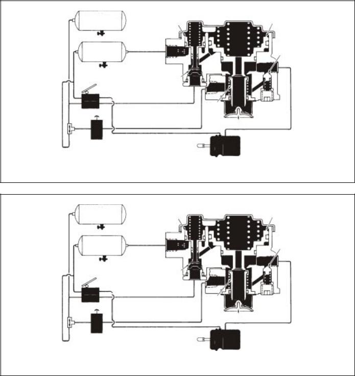
Air flowing from the No. 1 reservoir only enters the reservoir port of the SR-1™ valve. This air remains under piston A as system pressure builds. With No. 1 reservoir pressure below approximately 55 P.S.I. the spring above piston A forces it into contact with inlet and exhaust valve A causing the exhaust to seal and the inlet to open.
With air system pressure above approximately 55 P.S.I. in No. 1 & 2 service reservoirs, piston A has moved against the force of the spring above it, allowing the inlet of valve A to close and opening the hollow exhaust passage through piston A.
OPERATION - AIR BRAKE SYSTEM FULLY CHARGED
When air pressure beneath piston B is approximately 95* P.S.I., piston B rises slightly, against the force of the springs above it, allowing the inlet of valve B to close. The exhaust through valve B remains closed. The closing of the inlet portion of valve B retains approximately 95* P.S.I. in the holdoff cavity of the spring brake actuators while allowing full air system pressure to build elsewhere.
*Note: Other spring brake hold-off pressures are supplied according to the vehicle manufacturer’s specifications. 95 P.S.I. was chosen only for the purpose of explanation.
1

PP-7™ |
|
|
|
|
CONTROL |
TP-3™ TRACTOR PROTECTION VALVE |
|
||
VALVE |
DS-1 |
|
|
|
|
|
SB-3 |
|
SB-3 |
PARK |
|
|
|
|
CONTROL |
|
|
|
|
LQ-4™ VALVE |
|
|
|
|
|
DOUBLE |
|
|
|
MODULATOR |
CHECK LP-3™ INDICATOR |
|
|
|
VALVE |
|
|
|
|
|
R-8™ |
|
|
|
|
#2 SERVICE |
R-8 |
™ |
|
|
VALVE |
|
||
|
RESERVOIR |
|
VALVE |
|
SUPPLY |
#1 SERVICE |
RESERVOIR |
RESERVOIR |
SB-3 |
SB-3 |
FIGURE 3 - PIPING DIAGRAM
#2 SERVICE |
PISTON A |
PISTON B |
RESERVOIR |
||
#1 SERVICE |
|
CHECK VALVE |
RESERVOIR |
|
|
|
|
|
|
INLET & |
|
|
EXHAUST A |
|
|
INLET |
|
|
& |
|
|
EXHAUST |
EXHAUST |
DOUBLE |
B |
|
CHECK |
|
|
VALVE |
|
|
PARK |
|
|
CONTROL |
SB-3 |
|
|
|
|
|
|
|
FIGURE 4 - CHARGING - BELOW 55 P.S.I. |
|
|
2
#2 SERVICE |
PISTON A |
PISTON B |
RESERVOIR |
||
#1 SERVICE |
|
CHECK VALVE |
RESERVOIR |
|
|
|
|
|
|
INLET & |
|
|
EXHAUST A |
|
|
|
INLET & |
|
|
EXHAUST |
DOUBLE |
|
B |
|
EXHAUST |
|
CHECK |
|
|
VALVE |
|
|
PARK |
|
|
CONTROL |
|
SB-3 |
|
|
FIGURE 5 - SYSTEM FULLY CHARGED
|
#2 SERVICE |
PISTON A |
PISTON B |
|
RESERVOIR |
||
|
|
|
|
|
#1 SERVICE |
|
CHECK VALVE |
|
RESERVOIR |
|
|
|
|
|
|
|
|
INLET & |
|
|
|
EXHAUST A |
|
|
|
INLET |
|
|
|
& |
|
|
|
EXHAUST |
|
DOUBLE |
|
B |
EXHAUST |
|
|
|
|
CHECK |
PARK CONTROL |
|
|
VALVE |
|
|
|
|
|
SB-3 |
|
FIGURE 6 - NORMAL SERVICE APPLICATION
OPERATION - NORMAL SERVICE
RESERVOIRS 1 & 2 CHARGED
When a service application is made by actuating the dual brake valve, air from the No. 2 delivery circuit is delivered from the brake valve to the control port, and is stopped at the closed inlet of valve A. No movement of the internal components of the SR-1™ valve takes place. Air from the No. 1 delivery circuit of the dual brake valve actuates the service section of the spring brake actuators.
OPERATION - SERVICE APPLICATION WITH LOSS OF NO. 2 RESERVOIR PRESSURE
In the event air pressure is lost in the No. 2 reservoir, the No. 1 reservoir and the parking control valve will be protected via the double and single check valves in the air system. A service application of the foot brake valve in this situation results in little or no air being delivered from the No. 2 delivery circuit to the control port of the SR-1™ valve. No movement of the SR-1™ valve internal components takes place. Braking is assured because the No. 1 service reservoir is protected by a check valve and the No. 1 delivery circuit of the dual
3
 Loading...