


|
|
|
SD-01-333 |
Bendix® Tu-Flo® 550 Air Compressor |
|
|
|
DISCHARGE |
UNLOADER |
AIR DISCHARGE |
|
VALVE STOP |
COVER |
WATER OUTLET |
|
|
|
|
|
DISCHARGE |
|
|
|
VALVE |
|
WATER |
|
|
|
|
|
|
|
INLET |
|
DISCHARGE |
|
|
AIR INLET |
VALVE SEAT |
|
|
|
CRANKCASE |
DISCHARGE |
|
|
PISTON RINGS |
VALVE SPRING |
GOVERNOR |
CRANKCASE |
|
|
MOUNTING |
|
CONNECTING |
PISTON |
PAD |
|
|
|
||
ROD |
|
|
|
CRANKSHAFT
PIECE NO.
BENDIX® TU-FLO® 550 AIR COMPRESSOR TAG (CROSS SECTION)
DESCRIPTION
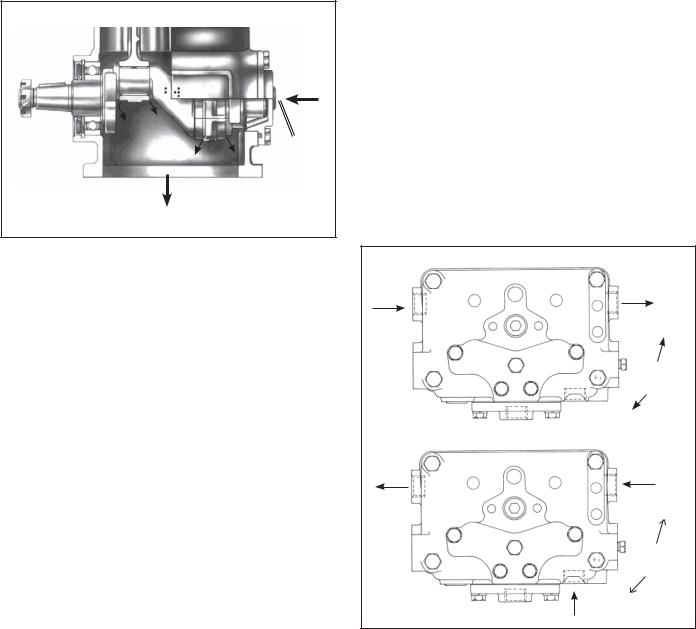
The function of the air compressor is to provide and maintain air under pressure to operate devices in the air brake and/or auxiliary air systems. The Bendix® Tu-Flo® 550 compressor is a two cylinder single stage, reciprocating compressor with a rated displacement of 13.2 cubic feet per minute at 1250 RPM.
The compressor assembly consists of two major subassemblies, the cylinder head and the crankcase. The cylinder head is an iron casting which houses the inlet, discharge, and unloader valving. (See Figure 1.) The cylinder head contains the air inlet port and is designed with both top and side air discharge ports. Three water coolant ports provide a choice of coolant line connections. Governor mounting surfaces are provided at both the front and the rear of the cylinder head. The head is mounted on the crankcase and is secured by six cap screws. The Tu-Flo® 550 compressor is designed such that the cylinder head can be installed in one of two positions which are 180 degrees apart. The crankcase houses the cylinder bores, pistons, crankshaft and main bearings, and provides the flange or base mounting surface.
BENDIX® TU-FLO® 550 AIR COMPRESSOR (EXTERIOR)
UNLOADER
CYLINDER
HEAD
INLET VALVE
INLET VALVE
SEAT
INLET
INLET VALVE
SPRING
END VIEW OF CYLINDER HEAD

|
UNLOADER COVER |
|
AIR DISCHARGE |
PLATE |
|
|
|
|
|
AIR |
|
|
DISCHARGE |
|
|
WATER |
|
|
AIR INLET |
WATER |
WATER |
|
GOVERNOR |
|
|
FIGURE 1 - CYLINDER HEAD
CAT MACK |
MACK |
MACK |
CUMMINS |
DETROIT |
CAT |
BASE |
(MACK STYLE) |
EXTENDED |
"FOXHEAD" |
|
DIESEL |
|
MOUNT |
FIGURE 2 - FLANGE CONFIGURATIONS
Various mounting and drive configurations, as shown in Figure 2, are supplied as required by the vehicle engine designs. A nameplate identifying the compressor piece number and serial number is attached to the side of the crankcase. (Reference Figure 3.)
TU-FLO® 550 COMPRESSOR |
BENDIX NO. |
SERIAL NO. |
MANUFACTURED BY BENDIX |
FIGURE 3 - NAMEPLATE
OPERATION
The compressor is driven by the vehicle engine and is operating continuously while the engine is running. Actual compression of air is controlled by the compressor unloading mechanism and the governor. The governor which is generally mounted on the compressor maintains the brake system air pressure to a preset maximum and minimum pressure level.
INTAKE AND COMPRESSION OF AIR (LOADED)
During the down stroke of the piston, a slight vacuum is created between the top of the piston and the cylinder head, causing the inlet valve to move off its seat and open. (Note: The discharge valve remains on its seat.) Atmospheric air is drawn through the air strainer and the open inlet valve into the cylinder (see Figure 4). As the piston begins its upward stroke, the air that was drawn into the cylinder on the down stroke is being compressed. Air pressure on the inlet valve plus the force of the inlet spring, returns the inlet valve to its seat and closes. The piston continues the upward stroke and compressed air pushes the discharge valve off its seat and air flows by the open discharge valve, into the discharge line and to the reservoirs (see Figure 5). As the piston reaches the top of its stroke and starts down, the discharge valve spring and air pressure in the discharge line returns the discharge valve to its seat. This prevents the compressed air in the discharge line from returning to the cylinder bore as the intake and compression cycle is repeated.

AIR |
|
|
UNLOADER |
|
GOVERNOR |
DISCHARGE |
PISTON |
GOVERNOR |
|
DISCHARGE |
PORT |
PORT |
|
PORT |
PORT |
|
|
|
|
|
|
|
AIR |
|
AIR |
|
INLET |
|
INLET |
|
PORT |
|
PORT |
|
|
|
INLET |
|
INLET VALVE |
DISCHARGE |
VALVE |
DISCHARGE |
HELD OPEN |
VALVE |
OPEN |
VALVE |
BY UNLOADER |
CLOSED |
|
CLOSED |
PISTON |
|
|
||
|
PISTON |
|
|
|
MOVING |
|
|
|
DOWN |
|
|
FIGURE 4 - OPERATIONAL-LOADED (INTAKE)
AIR |
GOVERNOR |
DISCHARGE |
PORT |
PORT |
|
AIR
INLET
PORT
|
INLET |
|
DISCHARGE |
VALVE |
|
CLOSED |
||
VALVE |
||
OPEN |
|
|
|
PISTON |
|
|
MOVING |
|
|
UP |
FIGURE 5 - OPERATIONAL-LOADED (COMPRESSION)
NON-COMPRESSION OF AIR (UNLOADED)
When air pressure in the reservoir reaches the cut-out setting of the governor, the governor allows air to pass from the reservoir, through the governor and into the cavity above the unloader pistons. The unloader pistons move down holding the inlet valves off their seats (see Figure 6.)
With the inlet valves held off their seats by the unloader pistons, air is pumped back and forth between the two cylinders, and the discharge valves remain closed. When air pressure from the reservoir drops to the cut-in setting of the governor, the governor closes and exhausts the air from above the unloader pistons. The unloader springs
FIGURE 6 - OPERATIONAL-UNLOADED
force the pistons upward and the inlet valves return to their seats. Compression is then resumed.
COMPRESSOR & THE AIR BRAKE SYSTEM
GENERAL
The compressor is part of the total air brake system, more specifically, the charging portion of the air brake system. As a component in the overall system its condition, duty cycle, proper installation and operation will directly affect other components in the system.
Powered by the vehicle engine, the air compressor builds the air pressure for the air brake system. The air compressor is typically cooled by the engine coolant system, lubricated by the engine oil supply and has its inlet connected to the engine induction system.
As the atmospheric air is compressed, all the water vapor originally in the air is carried along into the air system, as well as a small amount of the lubricating oil as vapor. If an air dryer is not used to remove these contaminants prior to entering the air system, the majority, but not all, will condense in the reservoirs. The quantity of contaminants that reach the air system depends on several factors including installation, maintenance and contaminant handling devices in the system. These contaminants must either be eliminated prior to entering the air system or after they enter.
DUTY CYCLE
The duty cycle is the ratio of time the compressor spends building air to the total engine running time. Air compressors are designed to build air (run "loaded") up to 25% of the time. Higher duty cycles cause conditions that affect air

Discharge |
Optional “Ping” Tank |
Line |
Air Dryer |
The Air Brake Charging System supplies the compressed air for the braking system as well as other air accessories for the vehicle. The system usually consists of an air compressor, governor, discharge line, air dryer, and service reservoir.
Optional Bendix® PuraGuard QC™
 Oil Coalescing Filter
Compressor |
|
Governor |
Service Reservoir |
(Governor plus Synchro valve |
|
for the Bendix® DuraFlo™ 596 |
(Supply Reservoir) |
Compressor) |
Reservoir Drain |
|
|
FIGURE 6A - SYSTEM DRAWING |
|
brake charging system performance which may require additional maintenance. Factors that add to the duty cycle are: air suspension, additional air accessories, use of an undersized compressor, frequent stops, excessive leakage from fittings, connections, lines, chambers or valves, etc. Refer to Table A in the Troubleshooting section for a guide to various duty cycles and the consideration that must be given to maintenance of other components.
COMPRESSOR INSTALLATION
While the original compressor installation is usually completed by the vehicle manufacturer, conditions of operation and maintenance may require additional consideration. The following presents base guidelines.
DISCHARGE LINE
The discharge line allows the air, water-vapor and oil-vapor mixture to cool between the compressor and air dryer or reservoir. The typical size of a vehicle's discharge line, (see column 2 of Table A in the Troubleshooting section) assumes a compressor with a normal (less than 25%) duty cycle, operating in a temperate climate. See Bendix and/or other air dryer manufacturer guidelines as needed.
The discharge line must maintain a constant slope down from the compressor to the air dryer inlet fitting or reservoir to avoid low points where ice may form and block the flow. If, instead, ice blockages occur at the air dryer or reservoir inlet, insulation may be added here, or if the inlet fitting is a typical 90 degree fitting, it may be changed to a straight or 45 degree fitting. Shorter discharge line lengths or insulation may be required in cold climates.
While not all compressors and charging systems are equipped with a discharge line safety valve this component is recommended. The discharge line safety valve is
installed in the cylinder head (Tu-Flo® 550/750) or close to the compressor discharge port and protects against over pressurizing the compressor in the event of a discharge line freezeup.
DISCHARGE LINE TEMPERATURE
When the temperature of the compressed air that enters the air dryer is within the normal range, the air dryer can remove most of the charging system oil. If the temperature of the compressed air is above the normal range, oil as oil-vapor is able to pass through the air dryer and into the air system. Larger diameter discharge lines and/or longer discharge line lengths can help reduce the temperature.
The air dryer contains a filter that collects oil droplets, and a desiccant bed that removes almost all of the remaining water vapor. The compressed air is then passed to the air brake service (supply) reservoir. The oil droplets and the water collected are automatically purged when the governor reaches its "cut-out" setting.
HOLE
THREAD
FIGURE 6B - DISCHARGE LINE SAFETY VALVE
OIL
INLET
FIGURE 7 - LUBRICATION
For vehicles with accessories that are sensitive to small amounts of oil, we recommend installation of a Bendix® PuraGuard® QC™ oil coalescing filter, designed to minimize the amount of oil present.
LUBRICATION
The vehicle's engine provides a continuous supply of oil to the compressor. Oil is routed from the engine to the compressor oil inlet. An oil passage in the compressor crankshaft allows oil to lubricate the connecting rod crankshaft bearings. Connecting rod wrist pin bushings and crankshaft ball bearings are spray lubricated. An oil return line connected from the compressor drain outlet to the vehicle engine crankcase allows for oil return. On flange mounted models the oil drains back directly to the engine through the mounting flange.
COOLING
Air flowing through the engine compartment from the action of the engine’s fan and the movement of the vehicle assists in cooling the compressor. Coolant flowing from the engine’s cooling system through connecting lines enters the head and passes through internal passages in the cylinder head and is returned to the engine. Proper cooling is important in maintaining discharge air temperatures below the maximum recommended 400 degrees Fahrenheit.
Figure 8 illustrates the various approved coolant flow connections. See the tabulated technical data in the back of this manual for specific requirements.
AIR INDUCTION
There are three methods of providing clean air to the TuFlo® 550 compressor:
1.Naturally aspirated Local Air Strainer - Compressor utilizes its own attached air strainer (polyurethane sponge or pleated paper dry element).
2.Naturally aspirated Engine Air Cleaner - Compressor inlet is connected to the engine air cleaner or the vacuum side (engine air cleaner) of the supercharger or turbocharger.
3.Pressurized induction - Compressor inlet is connected to the pressure side of the supercharger or turbocharger.
See the tabulated technical data on page 14 of this manual for specific requirements for numbers 2 and 3 above.
If a previously unturbocharged compressor is being turbocharged, it is recommended that the inlet cavity screen (238948) be installed with an inlet gasket (291909) on both sides of the screen.
WATER
IN
WATER
OUT
OR
(1 PORT ONLY)
 WATER OUT
WATER |
WATER |
OUT |
IN |
OR
(1 PORT ONLY)
WATER
IN
FIGURE 8 - COOLING

COMPRESSOR TURBOCHARGING PARAMETERS
Air entering the compressor inlet during the loaded cycle must not exceed 250 degrees Fahrenheit (121 degrees Celsius). A metal inlet line is suggested to help meet this parameter.
The following compressor crankshaft rotative speed and inlet pressure relationships may not be exceeded.
Crankshaft |
Maximum Compressor |
R.P.M. |
Inlet Pressure |
2200 RPM |
30.0 psi (207 kPa) |
2600 RPM |
25.0 psi (172.5 kPa) |
|
40 |
|
|
|
|
|
|
|
|
|
(PSIG) |
35 |
|
|
|
|
|
|
|
|
|
30 |
|
|
|
|
|
|
|
|
||
25 |
|
|
|
|
|
|
|
|
||
Pressure |
20 |
|
|
|
|
|
|
|
|
|
15 |
|
|
|
|
|
|
|
|
||
10 |
|
|
|
|
|
|
|
|
||
|
|
|
|
|
|
|
|
|
||
Inlet |
5 |
|
|
|
|
|
|
|
|
|
0 |
600 |
900 |
1200 |
1500 |
1800 |
2100 |
2400 |
2700 |
||
|
Compressor Speed (RPM)
Turbo Limits
FIGURE 9 - TURBO LIMITS CURVE
PREVENTIVE MAINTENANCE
Regularly scheduled maintenance is the single most important factor in maintaining the air brake charging system. Refer to Table A in the Troubleshooting section for a guide to various considerations that must be given to the maintenance of the compressor and other related charging system components.
Important Note: Review the warranty policy before performing any intrusive maintenance procedures. An extended warranty may be voided if intrusive maintenance is performed during this period.
AIR INDUCTION
One of the single most important aspects of compressor preventive maintenance is the induction of clean air. The type and interval of maintenance required will vary depending upon the air induction system used.
The intervals listed under the headings below pertain to typical highway and street operation. More frequent maintenance will be required for operation in dusty or dirty environments.
POLYURETHANE SPONGE STRAINER
Every month, 150 operating hours or 5,000 miles, whichever occurs first, remove and wash all of the parts. The strainer element should be cleaned or replaced. If the element is cleaned, it should be washed in a commercial solvent or a detergent and water solution. The element should be saturated in clean engine oil, then squeezed dry before replacing it in the strainer. Be sure to replace the air strainer gasket if the entire strainer is removed from the compressor intake.
POLYURETHANE SPONGE STRAINER
PAPER AIR STRAINER DRY ELEMENT-PLEATED
FIGURE 10 - STRAINERS
DRY ELEMENT - PLEATED PAPER STRAINER
Every two months, 800 operating hours or 20,000 miles whichever occurs first, loosen the spring clip from the unhinged side of the mounting baffle and open the cover. Replace the pleated paper filter and secure the cleaned cover, making sure the filter is in position. Be sure to replace the air strainer gasket if the entire air strainer is removed from the compressor intake.
INTAKE ADAPTER
When the engine air cleaner is replaced: Some compressors are fitted with compressor intake adapters, which allow the compressor intake to be connected to the engine air induction system. In this case, the compressor receives a supply of clean air from the engine air cleaner. When the engine air filter is changed, the compressor intake adapter should be checked. If it is loose, remove the intake adapter, clean the strainer plate, if applicable, and replace the intake adapter gasket, and reinstall the adapter securely. Check line connections both at the compressor intake adapter and at the engine. Inspect the connecting line for ruptures and replace it if necessary.
COMPRESSOR COOLING
Every 6 months, 1800 operating hours or after each 50,000 miles whichever occurs first, inspect the compressor discharge port, inlet cavity and discharge line for evidence of restrictions and carboning. If excessive buildup is noted, thoroughly clean or replace the affected parts and closely inspect the compressor cooling system. Check all compressor coolant lines for kinks and restrictions to flow. Minimum coolant line size is 3/8" I.D. Check coolant lines for internal clogging from rust scale. If coolant lines appear suspicious, check the coolant flow and compare to the tabulated technical data present in the back of this manual. Carefully inspect the air induction system for restrictions.
LUBRICATION
Every six months, 1800 operating hours or 50,000 miles whichever occurs first, check external oil supply and return lines, if applicable, for kinks, bends, or restrictions to flow. Supply lines must be a minimum of 3/16" I.D. and return lines must be a minimum of 1/2" I.D. Oil return lines should slope as sharply as possible back to the engine crankcase and should have as few fittings and bends as possible. Refer to the tabulated technical data in the back of this manual for oil pressure minimum values.
Check the exterior of the compressor for the presence of oil seepage and refer to the TROUBLESHOOTING section for appropriate tests and corrective action.
OIL PASSING
All reciprocating compressors currently manufactured will pass a minimal amount of oil. Air dryers will remove the majority of oil prior to entrance into the air brake system. For particularly oil sensitive systems the Bendix® PuraGuard® QC™ oil coalescing filter can be used in conjunction with a Bendix air dryer.
If compressor oil passing is suspected, refer to the TROUBLESHOOTING section and TABLE A for the symptoms and corrective action to be taken. In addition,
Bendix has developed the "Bendix Air System Inspection Cup" or BASIC test to help substantiate suspected excessive oil passing. The steps to be followed when using the BASIC test are presented in APPENDIX A at the end of the TROUBLESHOOTING section.
COMPRESSOR DRIVE
Every six months, 1800 operating hours or 50,000 miles, whichever occurs first, check for noisy compressor operation, which could indicate a worn drive gear coupling, a loose pulley or excessive internal wear. Adjust and/or replace as necessary.
If the compressor is belt driven, check for proper belt and pulley alignment and belt tension. Check all compressor mounting bolts and retighten evenly if necessary. Check for leakage and proper unloader mechanism operation. Repair or replace parts as necessary.
Every 24 months, 7200 operating hours, or after each 200,000 miles, perform a thorough inspection, and depending upon the results of this inspection or experience, disassemble the compressor, clean and inspect all parts thoroughly, replace all worn or damaged parts using only genuine Bendix replacements or replace the compressor with a genuine Bendix remanufactured unit.
GENERAL SERVICE CHECKS
OPERATING TESTS
IN SERVICE OPERATING TESTS
Compressor Performance: Build-up Test
This test is performed with the vehicle parked and the engine operating at maximum recommended governed speed. Fully charge the air system to governor cut out (air dryer purges). Pump the service brake pedal to lower the system air pressure below 80 psi using the dash gauges. As the air pressure builds back up, measure the time from when the dash gauge passes 85 psi to the time it passes 100 psi. The time should not exceed 40 seconds. If the vehicle exceeds 40 seconds, test for (and fix) any air leaks, and then retest the compressor performance. If the vehicle does not pass the test the second time, use the Advanced Troubleshooting Guide for Air Brake Compressors, starting on page A-1 of this document to assist your investigation of the cause(s).
Note: All new vehicles are certified using the FMVSS 121 test (paragraph S5.1.1) by the vehicle manufacturer, however the above test is a useful guide for in-service vehicles.
Optional Comparative Performance Check
It may be useful to also conduct the above test with the engine running at high idle (instead of maximum governed
speed), and record the time taken to raise the system pressure a selected range (for example, from 90 to 120 psi, or from 100 to 120 psi, etc.) and record it in the vehicle’s maintenance files. Subsequent build-up times throughout the vehicle’s service life can then be compared to the first one recorded. (Note: the 40 second guide in the test above does not apply to this build-up time.) If the performance degrades significantly over time, you may use the Advanced Troubleshooting Guide for Air Brake Compressors, starting on page A-1 of this document, to assist investigation of the cause(s).
Note: When comparing build-up times, be sure to make an allowance for any air system modifications which would cause longer times, such as adding air components or reservoirs. Always check for air system leakage.
AIR LEAKAGE TESTS
Compressor leakage tests need not be performed on a
regular basis. These tests should be performed when; it
41
is suspected that discharge valve leakage is substantially affecting compressor build-up performance, or when it is suspected that the compressor is “cycling” between the load and unloaded modes due to unloader piston leakage.
These tests must be performed with the vehicle parked on a level surface, the engine not running, the entire air system completely drained to 0 P.S.I., and the inlet check valve detail parts removed, if applicable.
UNLOADER PISTON LEAKAGE
The unloader pistons can be checked for leakage as follows: with the cylinder head removed from the compressor and the inlet flange securely covered, apply 120 psi of air pressure to the governor port. Listen for an escape of air at the inlet valve area. An audible escape of air should not be detected.
DISCHARGE VALVE LEAKAGE
Unloader piston leakage must be repaired before this test is performed. Leakage past the discharge valves can be detected as follows: Remove the discharge line and apply shop air back through the discharge port. Listen for an escape of air at the compressor inlet cavity. A barely audible escape of air is generally acceptable.
If the compressor does not function as described above or if the leakage is excessive, it is recommended that it be returned to the nearest authorized Bendix distributor for a factory remanufactured compressor. If it is not possible, the compressor can be repaired using a genuine Bendix cylinder head maintenance kit. Retest the cylinder head after installation of the kit.
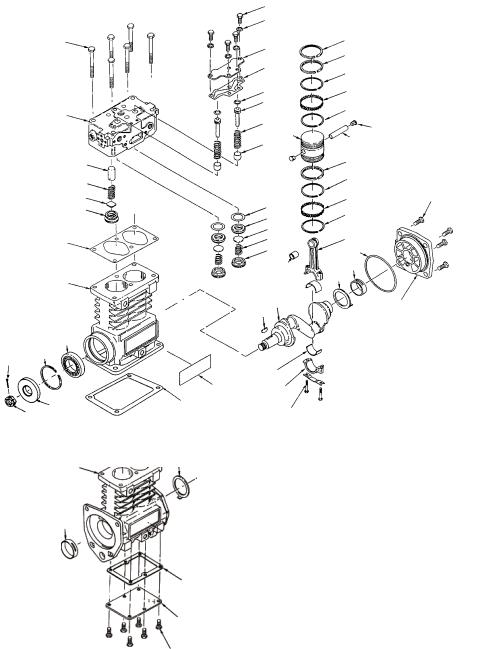
REMOVAL AND DISASSEMBLY
GENERAL
The following disassembly and assembly procedure is presented for reference purposes and presupposes that a major rebuild of the compressor is being undertaken. Several maintenance kits are available which do not require full disassembly. The instructions provided with these parts and kits should be followed in lieu of the instructions presented here.
REMOVAL
These instructions are general and are intended to be a guide, in some cases additional preparations and precautions are necessary.
1.Block the wheels of the vehicle and drain the air pressure from all the reservoirs in the system.
2.Drain the engine cooling system and the cylinder head of the compressor. Identify and disconnect all air, water and oil lines leading to the compressor.
3.Remove the governor and any supporting bracketry attached to the compressor and note their positions on the compressor to aid in reassembly.
4.Remove the discharge and inlet fittings, if applicable, and note their position on the compressor to aid in reassembly.
5.Remove the flange or base mounting bolts and remove the compressor from the vehicle.
6.Remove the drive gear(s) or pulley from the compressor crankshaft using a gear puller. Inspect the pulley or gear and associated parts for visible wear or damage. Since these parts are precision fitted, they must be replaced if they are worn or damaged.
PREPARATION FOR DISASSEMBLY
Remove road dirt and grease from the exterior of the compressor with a cleaning solvent. Before the compressor is disassembled, the following items should be marked to show their relationship when the compressor is assembled. Mark the rear end cover in relation to the crankcase. Mark the base plate or base adapter in relation to the crankcase.
A convenient method to indicate the above relationships is to use a metal scribe to mark the parts with numbers or lines. Do not use marking methods such as chalk that can be wiped off or obliterated during rebuilding.
CYLINDER HEAD
Remove the six cylinder head cap screws (1) and tap the head with a soft mallet to break the gasket seal. Remove the unloader cover plate cap screws (2), lockwashers (3) and the unloader cover plate (4). Scrape off any gasket
material (5) from the cover plate, cylinder head and crankcase.
1.Remove the unloader pistons (7), o-rings (6) and springs (8).
2.Inspect the unloader piston bushings (9) for nicks, wear, corrosion and scoring. It is recommended that the compressor be replaced if it is determined that the unloader bushing is damaged or worn excessively.
Before disassembling the discharge valve mechanism, measure and record the discharge valve travel (from closed to completely open).
3.If the measured discharge valve travel exceeds .046 inches, the compressor should be replaced. If the discharge valve travel does not exceed .046, using a 9/16" Allen wrench, remove the discharge valve seats (18), valves (17) and valve springs (16).
4.Remove the inlet valve stops (14), valves (17), valve seats (11), valve springs (12) and gaskets (10). It is recommended that a tool such as a J-25447-B, produced by Kent Moore Tool Division Roseville, Michigan phone 1-800-328-6657, be used to remove the inlet valve stop.
CRANKCASE BOTTOM COVER OR ADAPTER DISASSEMBLY
1.Remove the cap screws (22) securing the bottom cover or adapter (21). Tap with a soft mallet to break the gasket seal. Scrape off any gasket material (20) from the crankcase and bottom cover or adapter.
CONNECTING ROD DISASSEMBLY
Before removing the connecting rod, mark the connecting rods (37) and their caps (39) to ensure correct reassembly. The connecting rod and cap are a matched set therefore the caps must not be switched or rotated end for end.
1.Remove the connecting rod bolts (40) and bearing caps
2.Push the pistons (26) with the connecting rods
(37)attached out the top of the cylinder bore of the crankcase. Replace the bearing caps on the connecting rods.
3.Remove the piston rings (23-25) from the piston. If the piston is to be removed from the connecting rod, remove the wrist pin Teflon plugs (28) and press the wrist pin (27) from the piston and connecting rod.
4.If the piston is removed from the rod, inspect the wrist pin bore in the piston and bronze wrist pin bushing
(36)in the connecting rod. If excessive wear is noted or suspected, replace the connecting rod and piston.
COMPRESSOR CRANKCASE DISASSEMBLY
1.Remove the key or keys (30) from the crankshaft (29) and any burrs from the crankshaft where the key or keys were removed. (Note: Through drive compressors may have a crankshaft key at both ends.)
2.Remove the four cap screws (35) and lockwashers or nuts and lockwashers that secure the rear end cover (34) to the crankcase.
3.Remove the rear end cover (34), thrust washer (31) and end cover oil seal ring (33), taking care not to damage the bearing if present in the end cover.
4.If the compressor has ball type main bearings, press the crankshaft (29) and ball bearings from the crankcase, then press the ball bearings from the crankshaft.
5.Press the oil seal out of the compressor crankcase, if so equipped.
CLEANING OF PARTS
GENERAL
All parts should be cleaned in a good commercial grade of solvent and dried prior to inspection.
CYLINDER HEAD
Remove carbon deposits from the discharge cavity and rust and scale from the cooling cavities of the cylinder head body. Scrape all foreign matter from the body surfaces and use shop air pressure to blow the dirt particles from the cavities. Clean carbon and dirt from the inlet and unloader passages. Use shop air to blow the carbon and dirt deposits from the unloader passages.
OIL PASSAGES
Thoroughly clean all oil passages through the crankshaft, crankcase, end covers, base plate or base adapter. Inspect the passages with a wire to be sure. Blow the loosened foreign matter out with air pressure.
INSPECTION OF PARTS
CYLINDER HEAD BODY
Inspect the cylinder head for cracks or damage. With the cylinder head and head gasket secured to a flat surface or crankcase, apply shop air pressure to one of the coolant ports with all others plugged, and check for leakage by applying a soap solution to the exterior of the body. If leakage is detected, replace the compressor.
1
CYLINDER
HEAD
15
16
17
18
19
CRANKCASE
BASE
MOUNT
32
44 42
19
CRANKCASE
32
FLANGE
MOUNT
30
NAMEPLATE
20
31
20
21
22
2
3
4
5
6
7
89 26
10
11
12
13
14
36
29
38
39
40
23
23
24
25
24
27 |
28 |
|
|
23 |
|
24 |
|
25 |
35 |
24 |
|
37
33
32
34
32
BALL BEARING (MACK EXTENDED FLANGE)
|
ITEM |
QTY |
DESCRIPTION |
ITEM QTY |
DESCRIPTION |
ITEM |
QTY |
DESCRIPTION |
||
|
1 |
6 |
Cylinder Head Cap Screws |
16 |
2 |
Discharge Valve Spring |
31 |
2 |
Thrust Washer |
|
2 |
4 |
Unloader Plate Cap Screws |
17 |
2 |
Discharge Valve |
32 |
2 |
Sleeve (or Ball) Bearing |
||
|
3 |
4 |
Unloader Plate Lock Washers |
18 |
2 |
Discharge Valve Stop |
33 |
1 |
End Cover Seal |
|
4 |
1 |
Unloader Plate |
19 |
1 |
Cylinder Head Gasket |
34 |
1 |
End Cover |
||
|
5 |
1 |
Unloader Plate Gasket |
20 |
1 |
Base Gasket |
35 |
4 |
End Cover Cap Screws |
|
6 |
2 |
O-ring |
21 |
1 |
Base Plate |
36 |
2 |
Wrist Pin Bushing |
||
|
7 |
2 |
Unloader |
22 |
6 |
Base Plate Cap Screws |
37 |
2 |
Connecting Rod |
|
8 |
2 |
Spring |
23 |
6 |
Standard Piston Rings |
38 |
2 |
Conn. Rod Inserts (Sets) |
||
|
9 |
2 |
Unloader Bushing |
24 |
8 |
Oil Ring |
39 |
2 |
Connecting Rod Caps |
|
10 |
2 |
Gasket |
25 |
4 |
Expander Ring |
40 |
4 |
Connecting Rod Bolts |
||
|
11 |
2 |
Inlet Valve Seat |
26 |
2 |
Piston |
41 |
1 |
Ball Bearing |
|
12 |
2 |
Inlet Valve |
27 |
2 |
Wrist Pin |
42 |
1 |
Retaining Ring |
||
|
13 |
2 |
Inlet Valve Spring |
28 |
4 |
Wrist Pin Button |
43 |
1 |
Seal |
|
14 |
2 |
Inlet Valve Stop |
29 |
1 |
Crankshaft |
44 |
1 |
Cotter Pin |
||
|
15 |
2 |
Discharge Valve Stop |
30 |
1 |
Crankshaft Key |
45 |
1 |
Locknut |
|
|
|
|
|
|
|
|
|
|
|
|
END COVERS
Check for cracks and external damage. If the crankshaft main bearing (32) is installed in the end cover (34), check for excessive wear and flat spots and replace if necessary.
CRANKCASE
Check all crankcase surfaces for cracks and damage. On compressors where ball bearing main bearings are used the difference between the O.D. of the outer race and the I.D. of the crankcase hole should be .0003 in. tight to .0023 in. loose. This is to maintain the correct fit. The compressor must be replaced if the fit is too loose.
On compressors fitted with precision, sleeve main bearings, the difference between the O.D. of the crankshaft journal and the main bearing l.D. must not exceed .005 in. If the clearance is greater than .005 in. the bearing must be replaced.
The cylinder bores should be checked with inside micrometers or calipers. Cylinder bores which are scored or out of round by more than .0005 in. or tapered more than
.0005 in. should be re-bored or honed oversize. Oversized pistons and piston rings are available in .010 in., .020 in. and .030 in. oversizes. Cylinder bores must be smooth, straight and round. Clearance between the cast iron pistons and cylinder bores should be between .002 in. minimum and .004 in. maximum.
SIDE CLEARANCE |
|
|
|
|
.000 |
.002 |
EXPANDER |
.006 |
.004 |
|
|
RING |
|
|
STANDARD PISTON |
OIL RING |
|
RING |
|
|
END GAP |
Ring |
End |
|
Gap |
|
|
|
|
|
Compression |
.002 |
|
.013 |
|
|
|
|
|
Segment |
.010 |
|
|
.040 |
FIGURE 12 - RING CONFIGURATION
PISTON RINGS
Check the pistons for scores, cracks or enlarged ring grooves; replace the pistons if any of these conditions are found. Measure each piston with a micrometer in relation to the cylinder bore diameter to be sure the diametrical clearance is between .002 in. minimum and .004 in. maximum.
Check the fit of the wrist pins to the pistons and connecting rod bushings. The wrist pin should be a light press fit in the piston. If the wrist pin is a loose fit, the piston and pin assembly should be replaced. Check the fit of the wrist pin in the connecting rod bushing by rocking the piston. This clearance should not exceed .0007 in. Replace the connecting rod and cap assembly which includes the wrist pin bushings if excessive clearance is found. Check the fit of the rings in the piston ring grooves. Check the ring gap with the rings installed in the cylinder bores. Refer to Figure 12 for correct gap and groove clearances.
CRANKSHAFT
Check the crankshaft threads, keyways, tapered ends and all machined and ground surfaces for wear, scores, or damage. Standard crankshaft journals are 1.1242 in. - 1.1250 in. in diameter. If the crankshaft journals are excessively scored or worn or out of round and cannot be reground, the compressor must be replaced. Connecting rod bearing inserts are available in .010 in., .020 in. and .030 in. undersizes for compressors with reground crankshafts. Main bearing journals must be maintained so the ball bearings are a snug fit or so that no more than
.005 in. clearance exists between the precision sleeve main bearing and the main bearing journals on the crankshaft. Check to be sure the oil passages are open through the crankshaft.
CONNECTING ROD BEARINGS
Used bearing inserts must be replaced. The connecting rod and cap are a matched set and therefore the caps must not be switched or rotated end for end. The solid inserts must be installed in the rod and the slotted inserts into the cap. Make sure the locating tangs on the inserts engage with the locating notches in the rod and cap. Clearance between the connecting rod journal and the connecting rod bearing must not be less than .0003 in. or more than .0021 in. after rebuilding.
REPAIRS
UNLOADER
A new cylinder head maintenance kit should be used when rebuilding. Note: The entire contents of this kit must be used. Failure to do so may result in compressor failure. The unloader pistons in the kit are prelubricated

with a special lubricant piece number 239379 and need no additional lubrication. Install the springs and unloader pistons in their bores being careful not to cut the o-rings. Install the unloader cover gasket and unloader cover and secure the cover cap screws. Tighten the cap screws to 175-225 in. lbs. in a crossing pattern after first snugging all screws.
DISCHARGE VALVES, VALVE STOPS AND SEATS
If the discharge valve seats merely show signs of slight wear, they can be dressed by using a lapping stone, grinding compound and grinding tool, however, it is recommended that a cylinder head maintenance kit be used. Install new discharge valve springs and valves. Screw in the discharge valve seats, and tighten to 70-90 ft.-lbs. Discharge valve travel should be between .030 in. to
.046 in. To test for leakage by the discharge valves, apply 100 psi to the cylinder head discharge port and apply a soap solution to the discharge valve and seats. Leakage in the form of soap bubbles is permissible. If excessive leakage is found, leave the air pressure applied and with the use of a fiber or hardwood dowel and a hammer, tap the discharge valves off their seats several times. This will help the valves to seat and should reduce the leakage. With the air pressure still applied at the discharge port of the cylinder head, check for leakage around the discharge valve stop on the top of the cylinder head casting. No leakage is permitted.
INLET VALVES AND SEATS
Inlet valves and springs should be replaced. However, if the inlet valve seats show signs of slight nicks or scratches, they can be redressed with a fine piece of emery cloth or by lapping with a lapping stone, grinding compound and grinding tool. If the seats are damaged to the extent that they cannot be reclaimed, they must be replaced.
ASSEMBLY
General Note: All torques specified in this manual are assembly torques and typically can be expected to fall off after assembly is accomplished. Do not retorque after initial assembly torques fall unless instructed otherwise. A compiled listing of torque specifications is presented on page 13 of this manual.
To convert inch pounds of torque to foot pounds of torque, divide inch pounds by 12.
inch pounds ÷ 12 = foot pounds
To convert foot pounds of torque to inch pounds of torque, multiply foot pounds by 12.
foot pounds x 12 = inch pounds
INSTALLING CRANKSHAFT
Press new sleeve bearings in the end cover and crankcase. Ensure that the slot in the bearings line up with the oil passages in the end cover or crankcase. If you have a model with no oil passage present in the crankcase, press the sleeve bearing into the crankcase with the slot located 90 degrees from vertical.
Install the front thrust washer with the tang inserted in
PISTON COMPARISON
2.78 
1.25 |
1.06 |
|
2.17
TU-FLO® 550 |
OTHER BENDIX® |
AIR COMPRESSOR |
TU-FLO® AIR COMPRESSORS |
FIGURE 13 - PISTON COMPARISON
the slot toward the flange. Insert the crankshaft and the rear thrust washer with the tang toward the rear of the compressor.
Place the oil seal ring on the boss of the rear end cover and install the end cover making sure not to pinch the seal ring. Ensure the tang of the thrust washer is inserted in the slot of the end cover. Fasten the end cover to the crankcase with the four cover cap screws. Torque the cap screws to 175-225 inch pounds in a cross pattern.
COMPRESSION RING (23)
SEGMENT RING (24)
SPACER RING (25)
SEGMENT RING (24)
FIGURE 14 - PISTON & RINGS
 Loading...