


SD-08-2414
Bendix® AD-IP™ Integral Purge Air Dryer
DESICCANT
CARTRIDGE SADDLE
MOUNTING
BRACKET
MOUNTING
STRAP
SAFETY
VALVE
SAFETY VALVE CONTROL PORT
|
CONTROL |
|
LOWER |
|
|
MOUNTING |
|
|
PORT |
|
BRACKET |
HEATER & |
SUPPLY |
|
SUPPLY |
THERMOSTAT |
HEATER & THERMOSTAT |
PORT |
|
CONNECTOR |
PORT |
|
|
CONNECTOR |
|
||
|
|
|
FIGURE 1 - AD-IP™ INTEGRAL PURGE AIR DRYER
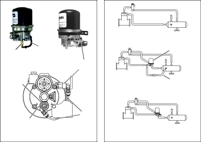
DESCRIPTION
The function of the Bendix® AD-IP™ integral purge air dryer is to collect and remove air system contaminants in solid, liquid and vapor form before they enter the brake system. It provides clean, dry air to the components of the brake system which increases the life of the system and reduces maintenance costs. Daily manual draining of the reservoirs is eliminated.
The AD-IP™ air dryer consists of a desiccant cartridge secured to a die cast aluminum end cover with a single, central bolt. The end cover contains a check valve assembly, safety valve, heater and thermostat assembly, three pipe thread air connections and the purge valve assembly. The removable purge valve assembly incorporates the purge valve mechanism and a turbo charger cutoff feature that is designed to prevent loss of engine “turbo” boost pressure during the purge cycle of theAD-IP™ air dryer. For ease of serviceability, all replaceable assemblies can be replaced without removal of the air dryer from its mounting on the vehicle.
The AD-IP™ air dryer has three female pipe thread air connections identified as follows:
Air Connection Port ID |
Function/Connection |
CON 4 ...................... |
Control Port (purge valve control |
|
& turbo cutoff). |
SUP 11 .................... |
Supply Port (air in). |
DEL 2 ...................... |
Delivery Port (air out). |
1
FEEDBACK
LINE
SPECIAL DISCHARGE
PORT FTG. W/
FEEDBACK LINE
CONNECTION CHECK VALVE
DISCHARGE
PORT
LOWER
MTG. BRKT.
(PARTIAL) FEEDBACK LINE
SPECIAL DISCHARGE
PORT FTG. W/
FEEDBACK LINE
CONNECTION END COVER
BOTTOM VIEW
FIGURE 2 - AD-IP™ DI DROP IN AIR DRYER FOR HOLSET
COMPRESSORS
AD-IP™ DI “DROP IN” AIR DRYER MODEL
In addition to the standard AD-IP™ air dryer, the Bendix® AD-IP™ DI (Drop In) air dryer is also offered. It is a specialized version designed especially for air systems that use either the Holset (Cummins) Type E or QE air compressor. These Holset compressors utilize an unusual unloading system that requires that air pressure remain in the discharge line during the entire unloaded cycle of the compressor. To accomplish this, Holset compressors rely on air “feedback” from the supply reservoir as shown in Figure 3B. When an air dryer is installed the direct “feedback” from the supply reservoir is interrupted and an alternate source for “feedback” pressure must be provided. A standard AD-IP™ air dryer can be installed, however a separate “feedback” line with a single check must be installed as shown in Figure 3C.
The AD-IP™ DI drop in air dryer model incorporates the feedback line and single check as an integral part of the dryer and eliminates the need for these components as shown in Figures 2 & 3C.
DISCHARGE LINE |
SUPPLY |
|
RES. |
HOLSET COMPRESSOR
FIGURE A
HOLSET TYPE E & QE COMPRESSORS - NO AIR DRYER
STANDARD AD-IP™ AIR
DRYER
SUPPLY
RES.
HOLSET
COMPRESSOR
FEEDBACK LINE
W/CHECK VALVE
FIGURE B
STANDARD AD-IP™ AIR DRYER AND
HOLSET TYPE E & QE COMPRESSORS
HOLSET
COMPRESSOR
AD-IP™ DI DROP IN AIR |
SUPPLY |
|
DRYER W/FEEDBACK |
||
RES. |
||
LINE & CHECK VALVE |
||
|
FIGURE C
AD-IP™ DI DROP IN AIR DRYER AND
HOLSET TYPE E & QE COMPRESSORS
FIGURE 3 - AD-IP™ AIR DRYER AND HOLSET TYPE E & QE
COMPRESSORS
OPERATION
GENERAL
The AD-IP™ air dryer alternates between two operational modes or “cycles” during operation: the Charge Cycle and the Purge Cycle. The following description of operation is separated into these “cycles” of operation.
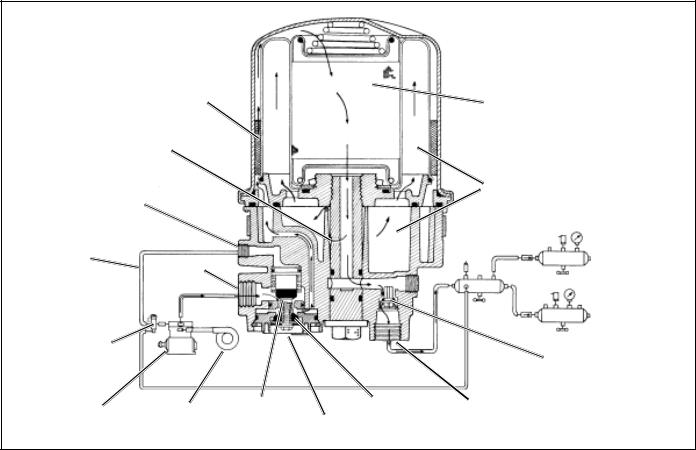
CHARGE CYCLE (refer to Figure 4)
When the compressor is loaded (compressing air) compressed air, along with oil, oil vapor, water and water vapor flows through the compressor discharge line to the supply port of the air dryer body.
As air travels through the end cover assembly, its direction of flow changes several times, reducing the temperature, causing contaminants to condense and drop to the bottom or sump of the air dryer end cover.
After exiting the end cover, the air flows into the desiccant cartridge. Once in the desiccant cartridge air first flows through an oil separator located between the outer and inner shells of the cartridge. The separator removes water in liquid form as well as liquid oil and solid contaminants.
2
OIL
SEPARATOR
DESICCANT
BED
PURGE
ORIFICE
PURGE
CONTROL VOLUME
PORT
PURGE |
|
|
CONTROL |
SUPPLY |
|
LINE |
||
PORT |
||
|
GOVERNOR |
|
|
|
DELIVERY |
|
|
|
|
|
|
|
|
|
CHECK VALVE |
|
|
|
|
(OLD STYLE |
|
|
|
PURGE |
SHOWN) |
|
|
TURBO |
DISCHARGE |
|
COMPRESSOR |
ENGINE |
VALVE |
||
|
TURBO |
CUTOFF |
EXHAUST |
PORT |
|
|
VALVE |
|
|
FIGURE 4 - AD-IP™ INTEGRAL PURGE AIR DRYER CHARGE CYCLE
Air, along with the remaining water vapor, is further cooled as it exits the oil separator and continues to flow upward between the outer and inner shells. Upon reaching the top of the cartridge the air reverses its direction of flow and enters the desiccant drying bed.Air flowing down through the column of desiccant becomes progressively drier as water vapor adheres to the desiccant material in a process known as
“ADSORPTION.” The desiccant cartridge using the adsorption process typically removes most of the water vapor from the pressurized air.
Dry air exits the bottom of the desiccant cartridge and flows through the center of the bolt used to secure the cartridge to the end cover. Air flows down the center of the desiccant cartridge bolt, through a cross drilled passage and exits the air dryer delivery port through the delivery check valve. Note: the early end cover designs incorporated a vertical delivery check valve while the newer versions have a horizontal check valve. Both have the same function, but the components are not interchangeable. See Figure 7.
Dry air flowing through the center of the desiccant cartridge bolt also flows out the cross drilled purge orifice and into the purge volume.
The air dryer will remain in the charge cycle until the air brake system pressure builds to the governor cutout setting.
PURGE CYCLE (refer to Figure 5)
As air brake system pressure reaches the cutout setting of the governor, the governor unloads the compressor (air compression is stopped) and the purge cycle of the air dryer begins. When the governor unloads the compressor, it pressurizes the compressor unloader mechanism and the line connecting the governor unloader port to the AD-IP™ air dryer end cover control port. The purge piston moves in response to air pressure causing the purge valve to open to the atmosphere and the turbo cutoff valve to close off the supply of air from the compressor (this will be further discussed in the Turbo Cutoff Feature section). Water and contaminants in the end cover sump are expelled immediately when the purge valve opens. Also, air which was flowing through the desiccant cartridge changes direction and begins to flow toward the open purge valve. Liquid oil and solid contaminants collected by the oil separator are removed by air flowing from the purge volume through the desiccant drying bed to the open purge valve.
The initial purge and desiccant cartridge decompression lasts only a few seconds and is evidenced by an audible burst of air at the AD-IP™ air dryer exhaust. No purging of air should occur after 30 seconds.
3

OIL
SEPARATOR
DESICCANT
BED
PURGE
ORIFICE
PURGE
CONTROL VOLUME
PORT
PURGE |
|
|
|
|
CONTROL |
SUPPLY |
|
|
|
LINE |
|
|
|
|
PORT |
|
|
|
|
|
|
|
|
|
GOVERNOR |
|
|
|
DELIVERY |
|
|
|
|
|
|
|
|
|
CHECK VALVE |
|
|
|
|
(OLD STYLE |
|
|
|
PURGE |
SHOWN) |
|
|
TURBO |
DISCHARGE |
|
COMPRESSOR |
ENGINE |
VALVE |
||
|
TURBO |
CUTOFF |
EXHAUST |
PORT |
|
|
VALVE |
|
|
FIGURE 5 - AD-IP™ INTEGRAL PURGE AIR DRYER PURGE CYCLE
PURGE
VOLUME
CONTROL
PORT
SUPPLY
PORT
TURBO
CUTOFF
VALVE
PURGE
VALVE
FIGURE 6 - AD-IP™ INTEGRAL PURGE AIR DRYER TURBO
CUTOFF
The actual reactivation of the desiccant drying bed begins as dry air flows from the purge volume through the purge orifice in the desiccant cartridge bolt, then through the center of the bolt and into the desiccant bed. Pressurized air from the purge volume expands after passing through the purge orifice; its pressure is lowered and its volume increased.
The flow of dry air through the drying bed reactivates the desiccant material by removing the water vapor adhering to it. Generally 30 seconds are required for the entire purge volume of a standard AD-IP™ air dryer to flow through the desiccant drying bed.
The delivery check valve assembly prevents air pressure in the brake system from returning to the air dryer during the purge cycle. After the 30 second purge cycle is complete the desiccant has been reactivated or dried. The air dryer is ready for the next charge cycle to begin. However the purge valve will remain open and will not close until air brake system pressure is reduced and the governor signals the compressor to charge the system.
TURBO CUTOFF FEATURE (Refer to Figure 6)
The primary function of the turbo cutoff valve is to prevent loss of engine turbocharger air pressure through the AD-IP™ air dryer in systems where the compressor intake is
4

DESICCANT |
|
|
|
BED |
|
|
|
OIL |
|
|
SPRING |
|
|
|
|
SEPARATOR |
|
|
|
|
DESICCANT |
|
|
|
CARTRIDGE |
|
|
PURGE |
|
|
|
ORIFICE |
|
|
|
|
PURGE |
|
PIPE PLUG |
|
|
|
|
CONTROL |
VOLUME |
|
|
PORT |
|
|
|
SUPPLY |
CHECK |
|
|
VALVE |
|
|
|
PORT |
|
|
|
(BLACK) |
|
|
|
|
|
|
|
TURBO |
|
|
DELIVERY |
CUTOFF |
|
|
PORT |
VALVE |
|
CARTRIDGE |
O-RING |
PURGE |
|
|
|
|
BOLT |
CHECK VALVE |
|
VALVE |
DELIVERY |
||
CARTRIDGE |
|
(WHITE) |
|
PORT |
|
||
BOLT |
|
|
|
|
|
|
|
Old Style End Cover -Vertical Delivery Check Valve |
New Style End Cover - Horizontal Delivery Check Valve |
||
FIGURE 7 - AD-IP™ AIR DRYER SECTIONAL VIEW
connected to the engine turbocharger. The turbo cutoff valve also removes the “puffing” of air out the open purge exhaust when a naturally aspirated, single cylinder compressor, equipped with an inlet check valve, is in use.
At the onset of the purge cycle, the downward travel of the purge piston is stopped when the turbo cutoff valve (tapered portion of purge piston) contacts its mating metal seat in the purge valve housing. With the turbo cutoff valve seated (closed position), air in the compressor discharge line and AD-IP™ air dryer inlet port cannot enter the air dryer. In this manner the turbo cutoff effectively maintains turbocharger boost pressure to the engine.
PREVENTIVE MAINTENANCE
Important: Review the warranty policy before performing any intrusive maintenance procedures.An extended warranty may be voided if intrusive maintenance is performed during this period. Note: It is acceptable for the purge valve to be maintained as necessary, i.e., the installation of a purge valve maintenance kit, without voiding the warranty.
Because no two vehicles operate under identical conditions, maintenance and maintenance intervals will vary. Experience is a valuable guide in determining the best maintenance interval for any one particular operation.
Every 900 operating hours, or 25,000 miles or three (3) months:
1.Check for moisture in the air brake system by opening reservoirs, drain cocks, or drain valves and checking for presence of water. If moisture is present, the desiccant cartridge may require replacement; however, the following conditions can also cause water accumulation and should be considered before replacing the desiccant:
A.An outside air source has been used to charge the system. This air does not pass through the drying bed.
B.Air usage is exceptionally high and not normal for a highway vehicle.
This may be due to accessory air demands or some unusual air requirement that does not allow the compressor to load and unload (compressing and non-compressing cycle) in a normal fashion. Check for high air system leakage. If the vehicle vocation has changed it may be necessary to upgrade the compressor size. Refer to Appendix A, Table A and the column entitled Vehicle Vocation.
C.The air dryer has been installed in a system that has been previously used without an air dryer. The system will be saturated with moisture and several weeks of operation may be required to dry it out.
5
Note: A small amount of oil in the system is normal and should not be considered as a reason to replace the desiccant cartridge; oil stained desiccant can function adequately.
2.Visually check for physical damage to the AD-IP™ air dryer such as chaffed or broken air and electrical lines and broken or missing parts.
3.Check mounting bolts for tightness. Re-torque to
270385 in.lbs.
4.Perform the Operation & Leakage Tests listed in this publication.
WARNING!
This air dryer is intended to remove moisture and other contaminants normally found in the air brake system. Do not inject alcohol, anti-freeze, or other de-icing substances into or upstream of the air dryer. Alcohol is removed by the dryer, but reduces the effectiveness of the device to dry air. Use of other substances can damage the air dryer and may void the warranty.
D.Location of the air dryer is too close to the air compressor. Refer to “Locating AD-IP™ Air Dryer On Vehicle” section and Appendix A, Table A, column 2 for discharge line length.
E.In areas where more than a 30 degree range of temperature occurs in one day, small amounts of water can temporarily accumulate in the air brake system due to condensation. Under these conditions, the presence of small amounts of moisture is normal and should not be considered as an indication that the dryer is not preforming properly.
OPERATION & LEAKAGE TESTS
1.Install a pressure gauge in the #1 reservoir. Check all lines and fittings leading to and from the air dryer for leakage and integrity. Test the delivery port check valve assembly by building the air system to governor cutout and observing a test air gauge installed in the #1 reservoir. Note the pressure on the air gauge after governor cutout pressure is reached, a rapid loss of pressure could indicate a failed delivery port check valve. This can be confirmed by shutting the engine off, draining system pressure to a point below governor cutin (usually not less than 95 psi), draining residual air pressure in the compressor discharge line. Remove the discharge line at the supply port of the dryer, and use soapy water to determine if air is flowing out of the supply port. Make sure there is no air pressure at the control port, by removing the line from the control port to the governor UNL port. The reservoir needs to have a least 50 PSIG for this test. If a 1” bubble forms within one second, the delivery check valve should be repaired. Remove the test gauge before returning the vehicle to service.
HEATER & |
AD-IP™ AIR |
THERMOSTAT |
DRYER END |
CONNECTOR |
COVER |
|
LOCKING LATCH |
|
(MUST BE INSERTED UNTIL IT |
|
SNAPS OVER THE MATING |
|
CONNECTOR ON AD-IP™ AIR DRYER |
SIDE VIEW |
WEATHERPROOF |
|
|
|
ACCORDIAN |
TOP VIEW |
SEAL |
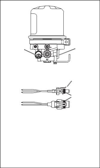
A two lead wire harness with attached weather resistant connector is supplied with all replacement and retrofit AD-IP™ air dryers. One of the two leads is connected to the engine “kill switch” or ignition while the other must be connected to a good vehicle ground. A fuse is installed in the lead carrying vehicle power; install a 10 amp fuse for 12 volt heaters and a 5 amp fuse for the 24 volt heater.
Use 14 AWG wire if it is necessary to lengthen the wire harness leads. Make certain all splices are weatherproofed. Tie wrap or support all electrical wires leading to the AD-IP™ air dryer.
FIGURE 8 - AD-IP™ AIR DRYER HEATER AND
THERMOSTAT CONNECTOR
2.Check for excessive leakage around the purge valve.
With the compressor in loaded mode (compressing air), apply a soap solution to the purge valve exhaust port and observe that leakage does not exceed a 1” bubble in 1 second. If the leakage exceeds the maximum specified, repair the purge valve assembly.
3.Close all reservoir drain cocks. Build up system pressure to governor cutout and note that AD-IP™ air dryer purges with an audible escape of air. “Fan” the service brakes to reduce system air pressure to governor cut-in. Note that the system once again builds to full pressure and is followed by an AD-IP™ air dryer purge.
4.Check the operation of the end cover heater and thermostat assembly during cold weather operation as follows:
6
A.Electric Power to the Dryer
With the ignition or engine kill switch in the ON position, check for voltage to the heater and thermostat assembly using a voltmeter or test light. Unplug the electrical connector at the air dryer and place the test leads on each of the pins of the connector with the locking latch. If there is no voltage, look for a blown fuse, broken wires, or corrosion in the vehicle wiring harness. Check to see if a good ground path exists.
B.Thermostat and Heater Operation
Note: These tests are not required except in cold weather operation.
Turn off the ignition switch and cool the thermostat and heater assembly to below 35 degrees Fahrenheit. Using an ohmmeter, check the resistance between the electrical pins in the air dryer connector half. The resistance should be 1.5 to 3.0 ohms for the 12 volt heater assembly and 6.0 to 9.0 ohms for the 24 volt heater assembly.
Warm the thermostat and heater assembly to over 90 degrees Fahrenheit and again check the resistance. The resistance should exceed 1000 ohms. If the resistance values obtained are within the stated limits, the thermostat and heater assembly is operating properly. If the resistance values obtained are outside the stated limits, replace the heater and thermostat assembly.
REBUILDING THE AD-IP™ AIR DRYER
GENERAL
If, after completing the routine operation and leakage tests, it has been determined that one or more components of the air dryer requires replacement or maintenance, refer to the following list to find the appropriate kit(s).
When rebuilding or replacing components of the air dryer use only genuine Bendix® parts. For ease in servicing, the AD-IP™ air dryer has been designed so that any of the following maintenance kits can be installed without removing the air dryer from the vehicle.
MAINTENANCE KITS AVAILABLE:
065624 ............... |
SERVICE NEW DESICCANT CARTRIDGE KIT |
This kit contains the parts necessary to change the desiccant cartridge only.
109493 ........REMANUFACTURED DESICCANT CARTRIDGE KIT
This kit contains the parts necessary to change the desiccant cartridge only.
5001247 ....................................... |
MOUNTING BRACKET KIT |
This kit contains the upper and lower brackets as well as the necessary hardware items to mount them.
109498 .............................................. |
CARTRIDGE BOLT KIT |
Contains a replacement desiccant cartridge bolt and related o-rings.
5003547 ............. |
PURGE VALVE HOUSING MAINTENANCE KIT |
This kit contains the parts necessary to rebuild the purge valve housing.
800404 ............................. |
PURGE VALVE REPLACEMENT KIT |
This kit contains the parts necessary to replace the purge valve.
5018313 ............................ |
PURGE VALVE MAINTENANCE KIT |
This kit contains the parts necessary to replace and relubricate the purge valve quad-ring and o-rings.
065626 .... SERVICE NEW PURGE VALVE HOUSING ASSEMBLY
Contains a service new assembly and related components to accomplish replacement.
109494 .............. |
DELIVERY CHECK VALVE MAINTENANCE KIT |
This kit contains the parts necessary to replace the delivery port check valve.
109495 ............................. |
12V HEATER & THERMOSTAT KIT |
109496 ............................. |
24V HEATER & THERMOSTAT KIT |
Each contains a replacement heater and thermostat assembly and related components required for replacement.
GENERAL SAFETY GUIDELINES
WARNING! PLEASE READ AND FOLLOW THESE INSTRUCTIONS TO AVOID PERSONAL INJURY OR DEATH:
When working on or around a vehicle, the following general precautions should be observed at all times.
1.Park the vehicle on a level surface, apply the parking brakes, and always block the wheels. Always wear safety glasses.
2.Stop the engine and remove ignition key when working under or around the vehicle. When working in the engine compartment, the engine should be shut off and the ignition key should be removed. Where circumstances require that the engine be in operation, EXTREME CAUTION should be used to prevent personal injury resulting from contact with moving, rotating, leaking, heated or electrically charged components.
3.Do not attempt to install, remove, disassemble or assemble a component until you have read and thoroughly understand the recommended procedures. Use only the proper tools and observe all precautions pertaining to use of those tools.
4.If the work is being performed on the vehicle’s air brake system, or any auxiliary pressurized air systems, make certain to drain the air pressure from
7
all reservoirs before beginning ANY work on the vehicle. If the vehicle is equipped with an AD-IS® air dryer system or a dryer reservoir module, be sure to drain the purge reservoir.
5.Following the vehicle manufacturer’s recommended procedures, deactivate the electrical system in a manner that safely removes all electrical power from the vehicle.
6.Never exceed manufacturer’s recommended pressures.
7.Never connect or disconnect a hose or line containing pressure; it may whip. Never remove a component or plug unless you are certain all system pressure has been depleted.
8.Use only genuine Bendix® replacement parts, components and kits. Replacement hardware, tubing, hose, fittings, etc. must be of equivalent size, type and strength as original equipment and be designed specifically for such applications and systems.
9.Components with stripped threads or damaged parts should be replaced rather than repaired. Do not attempt repairs requiring machining or welding unless specifically stated and approved by the vehicle and component manufacturer.
10.Prior to returning the vehicle to service, make certain all components and systems are restored to their proper operating condition.
11.For vehicles with Antilock Traction Control (ATC), the ATC function must be disabled (ATC indicator lamp should be ON) prior to performing any vehicle maintenance where one or more wheels on a drive axle are lifted off the ground and moving.
AD-IP™ AIR DRYER REMOVAL
This air dryer removal process is presented in the event it
becomes necessary to replace the entire air dryer. Normal service and parts replacement does not require removal of the air dryer from the vehicle.
1.Park the vehicle on a level surface and prevent movement by means other than the brakes.
2.Drain all reservoirs to 0 p.s.i. — Caution: Compressor discharge line may still contain residual pressure.
3.Identify and disconnect the three air lines from the end cover and note the position of end cover ports relative to the vehicle.
4.Unplug the vehicle wiring harness from the heater and thermostat assembly connector on the end cover assembly.
5.Remove the four bolts that secure both the upper and lower mounting brackets to the vehicle, and remove the air dryer from the vehicle.
6.Mark the relationship of the saddle bracket (5) to the end cover assembly (6). Remove the 5/16" cap screw
(1)and sleeve nut (3) securing the upper mounting strap
(4)to the saddle bracket (5). Earlier models used washer and nut in place of the sleeve nut (3). Remove the upper mounting strap (4) from the end cover assembly (6).
7.Mark the relationship of the lower bracket (9) to the end cover assembly (6). Remove the two 3/8" end cover cap screws (7) and two washers (8) that retain the lower mounting bracket (9) to the end cover (6).
DISASSEMBLY
The following disassembly and assembly procedure is presented for reference purposes and presupposes that a major rebuild of the AD-IP™ air dryer is being undertaken. The replacement parts and maintenance kits available generally do not require full disassembly. The instructions provided with these parts and kits should be followed in lieu of the instructions presented here. Refer to Figure 9 during disassembly.
Caution: While performing service on the AD-IP™ air dryer, it is not recommended that a clamping device (vise, C-clamp, etc.) be used to hold any die cast aluminum component as damage may result. To hold the end cover, install a pipe nipple in the supply port and clamp the nipple into a vise.
1.Using an adjustable or socket wrench, loosen the desiccant cartridge bolt (10), then separate the desiccant cartridge (11) from the end cover (6). Pull the desiccant cartridge bolt out of the end cover (6).
Caution: Disassembly of the desiccant cartridge assembly should not be attempted! Detail parts for the cartridge are not available and the cartridge contains a 150# spring which can not be mechanically caged.
2.Remove both o-rings (12 & 13) from the desiccant cartridge bolt.
3.Remove the retaining ring (14) that secures the purge valve assembly (15) in the end cover (6).
4.Remove the 1/4" shoulder bolt (16) from the bottom of the purge valve housing assembly (19) using a 3/8" socket wrench and a large blade screw driver, inserted in the slot on top of the purge piston (20). Remove the exhaust diaphragm (17), and the purge valve (18) from the purge valve housing (19).
5.Remove the o-rings (23 & 24) from the purge valve housing
(19). Discharge Line Unloader (DLU) models do not have o-ring (23).
6.Remove the purge piston (20) and the return spring (22).
7.Remove the o-ring (21) from the purge piston (20).
8
8.Vertical check valve models: Remove the retaining ring (25) that secures the delivery check valve assembly in the end cover (6). Remove and separate the perforated plate (26), spring (27), check valve body (28) and o-ring
9.Horizontal check valve models: Remove delivery check valve plug (34) that secures the check valve assembly in the end cover (6). Remove the spring (35), check valve (36) and o-ring (2).
10.Remove the retaining ring (30) that secures the heater and thermostat assembly (31) in the end cover (6). Gently pull the heater and thermostat (31) out of the end cover
(6)and remove the o-ring (32).
11.Using a 9/16” wrench, remove the safety valve assembly
(33)from the end cover (6).
CLEANING & INSPECTION
1.Using mineral spirits or an equivalent solvent, clean and thoroughly dry all metal parts except the desiccant cartridge.
2.Inspect the interior and exterior of all metal parts that will be reused for severe corrosion, pitting and cracks. Superficial corrosion and or pitting on the exterior portion of the end cover is acceptable.
3.Inspect the bores of both the end cover and the purge valve housing for deep scuffing or gouges.
4.Make certain that all purge valve housing and end cover passages are open and free of obstructions.
5.Inspect the pipe threads in the end cover. Make certain they are clean and free of thread sealant.
6.Inspect the purge valve housing bore and seats for excessive wear and scuffing.
7.Inspect the purge valve piston seat for excessive wear.
8.Make certain that the purge orifice in the cartridge bolt is open and free of obstructions.
9.Inspect all air line fittings for corrosion. Clean all old thread sealant from the pipe threads.
10.All o-rings removed should be discarded and replaced with new o-rings provided in appropriate kit(s).
ASSEMBLY
Prior to assembly, coat all o-rings, o-ring grooves, and bores with a generous amount of silicone grease. (Refer to Figures
9 and 10 during assembly unless otherwise advised.)
1.Install the quad ring (21) in its groove on the O.D. of the purge piston (20). Place the return spring (22) in the bore of the purge valve housing (19), then insert the purge piston (20) into the I.D. of the spring (22).
2.Install and center the exhaust diaphragm (17) over the shoulder bolt (16) making certain that the diaphragm ID is over the bolt shoulder. Then install the purge valve
(18)on the shoulder bolt making certain its metal support side is against the diaphragm (17).
3.Push the purge piston (20) into the housing (19) until it bottoms and insert a large blade screw driver in the piston’s slotted head. While depressing the purge piston with the screw driver, install the shoulder bolt (16) with exhaust diaphragm (17) and purge valve (18) in the piston. Torque the shoulder bolt (16) to between 60-80 in. lbs.
4.Install the two o-rings (23 & 24) on the purge valve housing
(19)placing each in its appropriate location. DLU models do not contain o-ring (23). Install the assembled purge valve housing in the end cover (6) while making certain the purge valve housing is fully seated against the end cover. Secure the purge valve housing in the end cover using the retaining ring (14). Make certain the retaining ring is fully seated in its groove in the end cover (6).
5.Using a 9/16” wrench, install the safety valve assembly
(33)into the end cover (6).
6.Vertical check valve models: Install the o-ring (29) on the check valve body (28) and push the o-ring down, over the 3 guide lands until it is in the o-ring groove of the check valve body (28). Install the check valve spring
(27)on the check valve body so that the small coils of
the spring slip over the check valve body. Install the assembled check valve body, o-ring, and spring (27, 28 & 29) in the end cover (6) so that the o-ring rests on its seat in the end cover (6) and the spring is visible. Install the perforated plate (26), in the end cover (6) and secure the check valve assembly using the retaining ring (25).
Make certain the retaining ring is fully seated in its groove in the end cover (6).
7.Horizontal check valve models: Install o-ring (2) onto check valve (36). Place the check valve in the delivery check valve port of the end cover (6). Install the spring
(35)over the delivery check valve (36) and secure with the delivery check valve plug (34).
8.Install the o-ring (32) on the heater and thermostat assembly (31). After making certain the sponge rubber cushion is positioned between the connector body and thermostat, gently push the heater and thermostat assembly (31) into the end cover (6), making certain the heating element enters the small diameter bore in the larger heater and thermostat bore in the end cover
(6).Secure the heater and thermostat assembly in the body using the retaining ring (30). Make certain the retaining ring is fully seated in its groove in the end cover
9.Install both o-rings (12 & 13) on the desiccant cartridge bolt (10) and using a twisting motion, insert the assembled desiccant cartridge bolt in the end cover (6).
9
 Loading...