


®
Bendix® R-7™ Modulating Valve
SD-03-4504
EXHAUST |
CONTROL |
|
||
|
PORT |
|
EXHAUST |
|
|
|
|
||
|
SUPPLY |
INLET |
|
|
MOUNTING |
VALVE |
|
||
PORT |
SPRING |
CONTROL |
||
HOLE (2) |
||||
|
|
|
PORT |
|
|
|
INLET |
CONTROL |
|
DELIVERY (2) |
|
EXHAUST |
PISTON |
|
|
VALVE |
DOUBLE CHECK |
||
|
|
MOUNTING |
VALVE(SUPPLY |
|
|
|
PORT & BALANCE |
||
|
|
SURFACE |
||
BALANCE |
|
PORT) |
||
|
INLET |
|||
PORT |
|
SINGLE |
||
|
|
VALVE |
||
|
|
SEAT |
CHECK |
|
|
|
BALANCE |
VALVE |
|
|
PISTON |
|
|
MOUNTING |
INNER SPRING |
DELIVERY |
|
PORT (2) |
|||
HOLE (2) |
|||
SUPPLY |
|||
|
|||
|
|
||
|
OUTER SPRING |
ADJUSTING SCREW |
|
|
|
BALANCE
CONTROL
EXHAUST
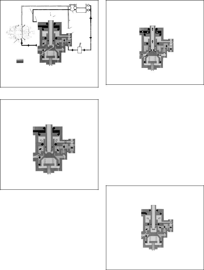
FIGURE 1 - EXTERIOR & INVERTED VIEW
DESCRIPTION
The R-7™ modulating valve is used in conjunction with a dual air brake system and spring brake actuators, and performs four functions:
1.Limits hold-off pressure to the spring brake actuators (adjustable).
2.Provides for quick release of air pressure from the spring cavity of the spring brake actuator allowing a fast application of the spring brake actuators.
3.Modulates spring brake actuator application should a failure occur in the service brake system.
4.Prevents compounding of service and spring forces.
The valve has one 1/4" control, one 3/8" supply, one 1/4" balance, two 3/8" delivery NPTF ports, and an exhaust port protected by an exhaust diaphragm. The valve incorporates two 13/32" holes for mounting.
FIGURE 2 - SECTIONAL VIEW
Note for model year 2001 and later International Trucks only: There is an inverted R-7™ valve, which appears inverted from the other pictures in this document. A standard R-7™ valve and an inverted R-7™ valve are not interchangeable. See Figure 1 for a picture of an inverted R-7™ valve.
OPERATION - CHARGING SPRING BRAKE ACTUATORS (FIGURE 3)
Air pressure used to control the spring brake actuators enters the valve through the supply port, passing through one side of the double check valve, through the open inlet valve, over the balance piston, and out the delivery ports to the spring brake actuators. When air pressure in the spring brake actuator cavity has released the spring brake actuators and when air pressure on top of the balance piston is sufficient to overcome the force of the balance piston spring, the balance piston moves allowing the inlet valve spring to close the inlet valve, shutting off further air pressure from the reservoir supplying the modulating valve.
1
|
|
|
#1 RES. |
SECONDARY SERVICE CIRCUIT |
|
|
|
|
EXHAUST |
|
#2 RES. |
|
|
|
|
CONTROL |
PORT |
CONTROL |
DUAL BRAKE |
|
|||
PORT |
|
PISTON |
VALVE |
|
|
|
PRIMARY |
|
|
|
SERVICE |
|
|
|
CIRCUIT |
|
|
|
BALANCE |
|
|
|
PORT |
|
|
|
DOUBLE |
|
|
|
CHECKVALVE |
SPRING |
|
|
SUPPLY |
BRAKE |
|
|
PORT |
ACTUATOR |
|
|
|
INLET/EXHAUST |
|
SINGLE |
PARK |
VALVE |
|
||
|
CHECK |
||
|
|
CONTROL |
|
|
|
VALVE |
|
|
|
VALVE |
|
|
|
|
|
PRIMARY - |
|
BALANCE PISTON |
|
SECONDARY - |
|
|
|
PARK -
+ SPRING BRAKE HOLD-OFF PRESSURE - SERVICE AIR PRESSURE
o ATMOSPHERE PRESSURE
FIGURE 3 - CHARGING
|
|
|
|
#1 RES. |
|
SECONDARY |
|
EXHAUST |
|
#2 RES. |
|
SERVICE |
CONTROL |
CONTROL |
|||
CIRCUIT |
PORT |
|
|||
PORT |
PISTON |
DUAL BRAKE |
|||
|
|
||||
|
|
|
|
VALVE |
|
|
|
|
|
PRIMARY SERVICE |
|
|
|
|
|
CIRCUIT |
|
|
|
|
|
BALANCE |
|
|
|
|
|
PORT |
|
|
|
|
|
DOUBLE |
|
|
|
|
|
CHECKVALVE |
SPRING
BRAKE
ACTUATOR
INLET/EXHAUST
VALVE
PRIMARY -
SECONDARY -
PARK -
|
SUPPLY |
|
PORT |
SINGLE |
PARK |
CHECK |
CONTROL |
VALVE |
VALVE |
BALANCE PISTON
+ SPRING BRAKE HOLD-OFF PRESSURE - SERVICE AIR PRESSURE
o ATMOSPHERE PRESSURE
SECONDARY SERVICE CIRCUIT |
|
#1 RES. |
|
|
|
EXHAUST |
|
#2 RES. |
CONTROL PORT |
CONTROL |
DUAL BRAKE |
PORT |
PISTON |
|
|
|
VALVE |
|
|
PRIMARY SERVICE |
|
|
CIRCUIT |
|
|
BALANCE |
|
|
PORT |
|
|
DOUBLE |
|
|
CHECK |
|
|
VALVE |
|
|
SUPPLY |
SPRING |
|
PORT |
BRAKE |
|
|
ACTUATOR |
SINGLE |
PARK |
|
||
|
CHECK |
CONTROL |
INLET/EXHAUST |
VALVE |
VALVE |
VALVE |
|
|
PRIMARY - |
BALANCE PISTON |
|
SECONDARY - |
|
|
PARK - |
|
|
+ SPRING BRAKE HOLD-OFF PRESSURE - SERVICE AIR PRESSURE
o ATMOSPHERE PRESSURE
FIGURE 5 - SERVICE APPLICATION LOSS OF PRIMARY CIRCUIT
OPERATION - SERVICE APPLICATION WITH LOSS OF AIR IN PRIMARY CIRCUIT (FIGURE 5)
A service application made with a loss of air in the primary circuit would result in reduced air pressure delivered to the lower area of the control piston. Air pressure from the secondary circuit on top of the control piston would force the piston down, opening the exhaust valve and allowing air pressure in the spring cavity of the spring brake actuator to release and the spring brake actuator to apply the brakes.
The pressure differential between the primary and secondary circuits regulates the amount of air pressure released from the spring cavity of the spring brake actuator. This results in a total brake application on the rear axle which is proportionate to the braking on the other axles.
FIGURE 4 - NORMAL SERVICE APPLICATION
NOTE: The force of the spring below the balance piston is adjustable by an external screw on the modulating valve. This adjustment is normally made so that the inlet valve will close at a slightly greater pressure than the hold-off pressure of the spring brake actuator, but below maximum system pressure.
OPERATION - NORMAL SERVICE APPLICATION (FIGURE 4)
When a service application is made by actuating the dual brake valve, air from the primary circuit is delivered to the lower side of the control piston through the balance port, and air from the secondary circuit is delivered to the top of the control piston through the control port. Because air pressure from the primary and secondary circuits are not equal, there will be a slight movement of the control piston.
|
|
|
#1 RES. |
SECONDARY |
|
|
|
SERVICE |
EXHAUST |
|
#2 RES. |
CIRCUIT |
PORT |
CONTROL |
DUAL BRAKE |
CONTROL |
|
||
PORT |
|
PISTON |
VALVE |
|
|
|
PRIMARY SERVICE |
|
|
|
CIRCUIT |
|
|
|
BALANCE PORT |
|
|
|
DOUBLE |
|
|
|
CHECKVALVE |
SPRING
BRAKE
ACTUATOR INLET/EXHAUST VALVE
PRIMARY -
SECONDARY -
PARK -
SUPPLY
PORT
SINGLE |
PARK |
|
CONTROL |
||
CHECK |
||
VALVE |
||
VALVE |
||
|
||
BALANCE PISTON |
|
+ SPRING BRAKE HOLD-OFF PRESSURE - SERVICE AIR PRESSURE
o ATMOSPHERE PRESSURE
FIGURE 6 - SERVICE APPLICATION LOSS OF SECONDARY CIRCUIT
2
 Loading...