


SD-13-4869

®
Bendix® EC-60™ ABS / ATC / ESP Controllers (Advanced)
See SD-13-4863 for Standard and Premium Controllers
See SD-13-21021 for the Bendix
®
eTrac™ Automated Air Suspension Transfer System
The driver is always responsible for the control
and safe operation of the vehicle at all times. The
Bendix® ESP® stability system does not replace the
need for a skilled, alert professional driver, reacting
appropriately and in a timely manner, and using safe
driving practices.
SD-13-4869
All Four Connectors Are Used.
(If only two or three connectors are in
use - see SD-13-4863)
™
FIGURE 1 - EC-60
ADVANCED CONTROLLER
INTRODUCTION
The Bendix® EC-60™ advanced controller is a member
of a family of electronic Antilock Braking System
(ABS) devices designed to help improve the braking
characteristics of air braked vehicles - including heavy- and
medium-duty buses, trucks, and tractors. ABS controllers
are also known as Electronic Control Units (ECUs).
Bendix® ABS uses wheel speed sensors, ABS pressure
modulator valves, and an ECU to control either four or six
wheels of a vehicle. The Bendix EC-60 controller monitors
individual wheel turning motion during braking and adjusts
or modulates the brake pressure at the wheel end. When
excessive wheel slip, or wheel lock-up is detected, the
Bendix EC-60 controller will activate the pressure modulator
valves to automatically reduce the brake pressure at one
or more of the wheel ends. By these actions, the ABS
system helps to maintain the vehicle's lateral stability and
steerability during heavy brake applications and during
braking on slippery surfaces.
In addition to the ABS function, advanced models of the
EC-60™ controller provide ABS-based stability features
referred to as ESP® Electronic Stability Program. The
Bendix ESP system is an ABS-based stability system that
enhances vehicle stability by both reducing engine throttle
and by applying vehicle braking based on actual vehicle
dynamics. Accordingly, the ESP system is available only on
specic approved vehicle platforms after vehicle application
and development efforts and validation testing. Only
certain limited variations of an approved vehicle platform
are permitted without further validation of the ESP system
application.
ESP stability system consists of Yaw Control (YC) and Roll
Stability Program (RSP) features.
ESP® is a registered trademark of DaimlerChrysler and is used by BCVS under license from DaimlerChrysler.
TABLE OF CONTENTS PAGE
General System Information
Introduction. . . . . . . . . . . . . . . . . . . . . . . 1
Components . . . . . . . . . . . . . . . . . . . . . 3-4
HardwareCongurations . . . . . . . . . . . . . . . 4
Bendix EC-60 Controller Inputs & Outputs . . . . . 5-7
Indicator Lamps and Power-Up Sequence . . . . . 8-9
ABS Operation . . . . . . . . . . . . . . . . . . . . . 9
ATC Operation . . . . . . . . . . . . . . . . . . 11-12
Advanced ABS With Stability . . . . . . . . . . 12-13
Important Safety Information About
The ESP Stability System . . . . . . . . . . . . 13-14
Dynamometer Test Mode . . . . . . . . . . . . . . 14
System Impact During Active Trouble Codes . . . 15
SystemReconguration . . . . . . . . . . . . . . . 16
Troubleshooting . . . . . . . . . . . . . . . . . 17-48
Sensor Calibration . . . . . . . . . . . . . . . . 17-19
Blink Codes and Diagnostic Trouble Codes . . 21-23
Wiring Schematic . . . . . . . . . . . . . . . . . . 48
Glossary. . . . . . . . . . . . . . . . . . . . . . . . 49
J1587 SID and FMI Codes . . . . . . . . . . . . 51-55
UDS Codes . . . . . . . . . . . . . . . . . . . . 56-60
Additional features include Automatic Traction Control
(ATC). Bendix ATC can improve vehicle traction during
acceleration, and lateral stability while accelerating through
curves. ATC utilizes Engine Torque Limiting (ETL)
where the ECU communicates with the engine’s controller
and/or Differential Braking (DB) where individual wheel
brake applications are used to improve vehicle traction.
Advanced Bendix EC-60 controllers have a drag torque
control feature which reduces driven-axle wheel slip (due
to driveline inertia) by communicating with the engine’s
controller and increasing the engine torque.
For vehicles with the Hill Start Feature optional feature,
this system interfaces between the transmission and
braking system to help the driver prevent the vehicle from
rolling downhill when moving up a steep incline from a
stationary position.
1

CAUTION
Even with ESP-equipped vehicles, the driver remains
responsible for ensuring vehicle stability during operation.
The ESP system can only function within the limits of
physics. ESP functionality mitigates potential vehicle
stability incidents, but cannot prevent them in all cases.
Other factors such as driving too fast for road, trafc or
weather conditions, oversteering, an excessively high
vehicle Center of Gravity (CG), or poor road conditions can
cause vehicle instability that is beyond the capability of any
stability system to mitigate. In addition, the effectiveness
of ESP can be greatly reduced on vehicles towing multiple
trailer combinations.
2
CAUTION
The ESP stability system may only be used on vehicles
tested and approved by Bendix engineering. ESP
installations require on-vehicle testing and Bendix® EC-60™
parameter tuning. See "Advanced ABS with Stability
Control" on page 12 for further details.
Accordingly, the Bendix EC-60 controller is provided with
a corresponding parameter data set that is validated for
a specic vehicle platform. Therefore, specic steps are
necessary should a replacement ECU be required. See
“Obtaining a New Bendix EC-60 Advanced Controller” on
page 18 for further details.
ESP-equipped vehicles should not be driven on highbanked roads – such as those found on high-speed test or
race tracks. Test personnel must have ESP functionality
disabled prior to operating an ESP vehicle on such tracks.
YAW CONTROL (YC)
Advanced ECU can include Yaw Control (YC) functionality,
which has the ability to apply brakes to individual wheel
ends, as well as applying the trailer brakes, to counteract
trailer “push” that, during certain maneuvers, could lead to
a loss-of-control or a jackknife incident. See "Yaw Stability"
on page 9 for further details.
Delivery
(Port 2)
Supply
(Port 1)
ROLL STABILITY PROGRAM (RSP)
The Bendix Roll Stability Program (RSP), is an all-axle
ABS solution that helps reduce vehicle speed by reducing
the engine's throttle and applying all vehicle brakes as
needed, reducing the vehicle's tendency to roll over. RSP
focuses on reducing the vehicle’s speed below the critical
roll threshold during direction-changing maneuvers such as
driving on curved highway exit ramps or obstacle avoidance
maneuvers on dry, high friction surfaces. See "Advanced
ABS with Stability Control" on page 12 for further details.
WARNING
During an RSP system intervention, the vehicle
automatically decelerates. RSP can slow the vehicle
with or without the operator applying the brake pedal,
and even when the operator is applying the throttle.
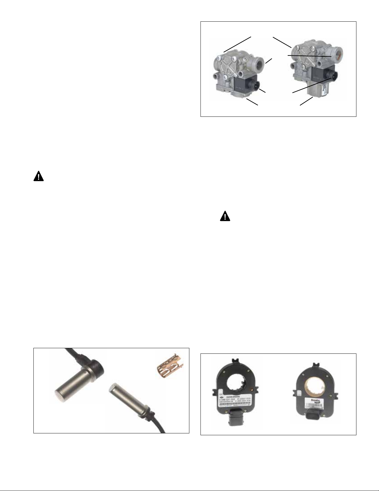
COMPONENTS
The Bendix EC-60 controller’s ABS function utilizes the
following components:
• Bendix® WS-24™ wheel speed sensors (4 or 6,
depending on configuration). Each sensor is
installed with a Bendix Sensor Clamping Sleeve
• Bendix® M-32™ or M-32QR™ Pressure Modulator
Valves (4, 5, or 6 depending on conguration)
• Dash-mounted tractor ABS Indicator Lamp
• Service brake relay valve
• Dash-mounted trailer ABS Indicator Lamp
• Optional blink code activation switch
• Optional ABS off-road switch
Sensor
90° Speed
Sensors
Clamping
Sleeve
Electrical
M-32QR
Modulator
FIGURE 3 - M-32™ AND M-32QR™ MODULATORS
™
Connector
Exhaust (Port 3)
™
M-32
Modulator
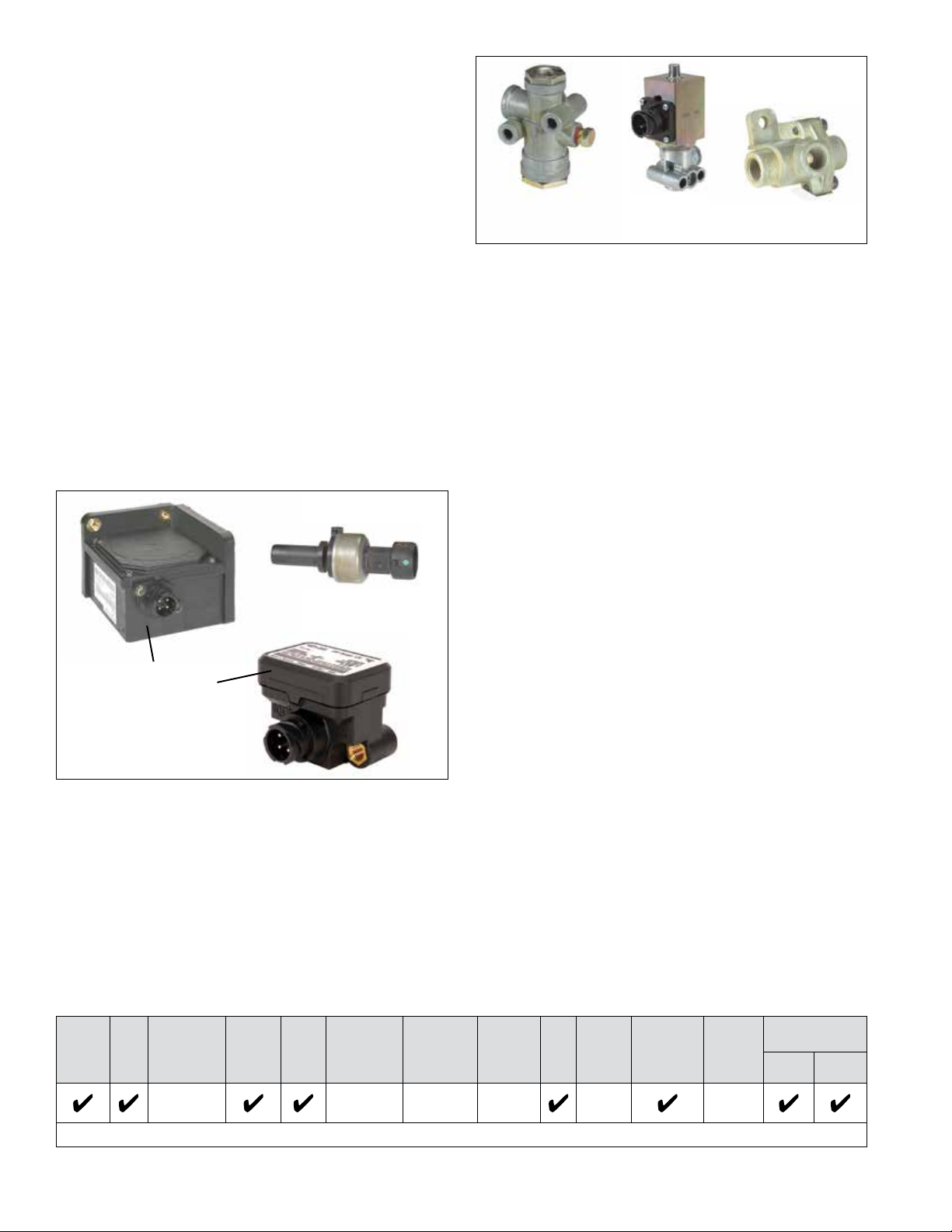
The Bendix EC-60 controller ESP/RSP function utilizes the
following additional components:
• Steer Axle Traction Control Valve (may be integral
to the service brake relay valve or a stand-alone
device)
• Dash-mounted ESP status/indicator lamp (also
serves as the ATC status/indicator lamp)
• Bendix SAS-60™ Steering Angle Sensor (mounted
to the steering column - See Figure 4)
CAUTION: When replacing a steering wheel,
take care not to damage the Steering Angle Sensor
or interfere with its operation, and the Steering Angle
Sensor must be recalibrated (see Troubleshooting
section)
• Bendix® YAS-60™ or YAS-70X™ Yaw Rate/Lateral
Acceleration Sensors (typically mounted to a crossmember near the back of the vehicle cab)
• Brake Demand Sensors (installed in the primary
and secondary delivery circuits)
• Load Sensor (typically installed in the suspension
air bag)
• An additional Modulator Valve (Bendix® M-32™ or
M-32QR™ Pressure Modulator Valve) that controls
pressure apply to trailer brakes during system
intervention
Straight Speed
Sensors
FIGURE 2 - BENDIX® WS-24™ WHEEL SPEED SENSORS
Straight
Connector
FIGURE 4 - STEERING ANGLE SENSORS
90°
Connector
3
The Bendix® EC-60™ controller ATC function utilizes the
following additional components:
• Drive axle traction control valve (may be integral
to the service brake relay valve or a stand-alone
device)
• Dash-mounted ATC status/indicator lamp
• J1939 serial communication to engine control
module
• Stop lamp switch input (may be provided using the
ECU hardware input or J1939)
• Optional ATC mud/snow switch (sometimes referred
to as an ATC off-road switch)
The EC-60 controller Hill Start Feature utilizes the following
additional components:
• Bendix® AT-3™ Traction control valve
• Dash-mounted HSA Status/indicator lamp
• Dash-mounted enable/disable Switch
• Bendix® RV-3™ Pressure reducing valve
• Bendix® DC-4® Double check valve
Brake Demand/
Load Sensor
®
Bendix® RV-3
Pressure
Reducing Valve
FIGURE 6 - ADDITIONAL VALVES NECESSARY FOR THE
HILL START FEATURE
™
Bendix® AT-3
Traction Control
Valve
™
Bendix
Double Check
Valve
DC-4
®
BENDIX® ETRAC™ AUTOMATED AIR
SUSPENSION TRANSFER SYSTEM
The Bendix® eTrac™ automated air pressure transfer
system is used on 6 x 2 semi-tractors that feature Bendix®
premium and advanced Antilock Brake Systems (ABS).
This system complements the Bendix® Smart Automatic
Traction Control (ATC™) feature of our ABS system to
provide improved traction at low speeds (e.g. pulling away
on an inclined ramp, or in slippery conditions such as mud
or snow-covered surfaces, etc.) When active, the Bendix
eTrac system vents — or “dumps” — the air pressure of
the tag axle suspension air bags, and increases the air
pressure in the drive axle suspension air bags to a predetermined maximum. This action helps the drive axle to
gain more traction.
See SD-13-21021 for more information.
Yaw/Lateral
Accelerator Sensors
(Two examples
shown.)
FIGURE 5 - YAW AND BRAKE DEMAND/LOAD SENSORS
ABS
Off-
Road
ATC
ATC
Mud/Snow
Blink
Codes
ESP/
RSP
HSA
Bendix
eTrac
system*
Optional Optional Optional 12/24 4/5/6 4/6
ECU MOUNTING
The Bendix® EC-60™ advanced cab-mounted controller is
not protected against moisture, and must be mounted in
an environmentally protected area.
All wire harness connectors must be properly seated. The
use of secondary locks is strongly recommended.
Cab ECUs utilize connectors from the AMP MCP 2.8
product family.
HARDWARE CONFIGURATIONS
Advanced Bendix® EC-60™ controllers support applications
up to six sensor/six modulator (6S/6M) installations with
ATC and drag torque control. They can support HSA
functions. All 12 volt models support PLC. 24 volt models
do not support PLC. See Chart 1 for more details.
®
™
Voltage
Input
PLC PMVs
Retarder
Relay
Sensors
Serial
Communication
J1587 J1939
For information about the Bendix® eTrac™ automated air suspension transfer system, see SD-13-21021
*
CHART 1 - BENDIX
4
®
EC-60™ ADVANCED CONTROLLER FEATURES
ADVANCED BENDIX EC-60 CONTROLLERS
USE POWER LINE CARRIER (PLC)
All new towing vehicles built since March 1, 2001 have had
an in-cab trailer ABS Indicator Lamp installed.
Trailers built since March 1, 2001 transmit the status of
the trailer ABS over the power line (the blue wire of the
J560 connector) to the tractor using a Power Line Carrier
(PLC) signal. See Figures 7 and 8. Typically the signal is
broadcast by the trailer ABS ECU.
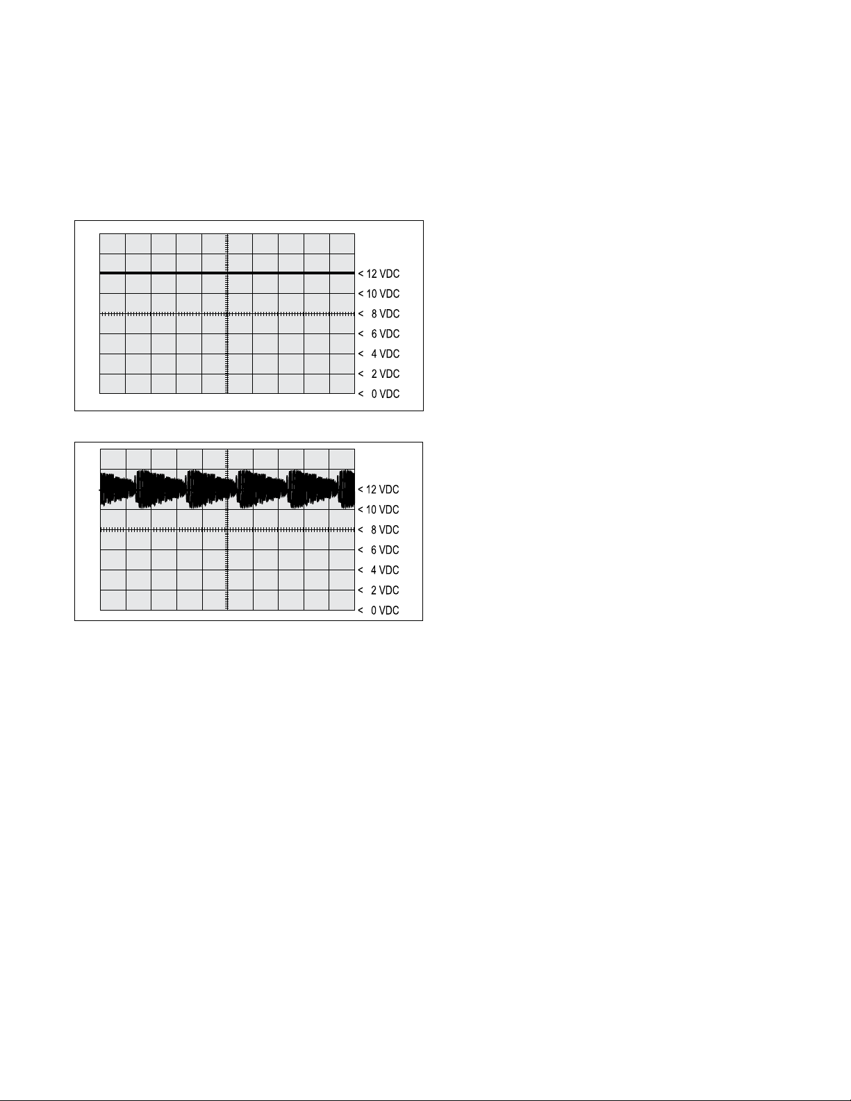
FIGURE 7 - POWER LINE WITHOUT PLC SIGNAL
FIGURE 8 - POWER LINE WITH PLC SIGNAL
The application of PLC technology for the heavy vehicle
industry in North America is known as “PLC4Trucks.”
The Advanced Bendix EC-60 controller supports PLC
communications in accordance with SAE J2497.
PLC SIGNAL
An oscilloscope can be used to measure or identify the
presence of a PLC signal on the power line. The PLC
signal is an amplitude and frequency modulated signal.
Depending on the ltering and load on the power line, the
PLC signal amplitude can range from 5.0mVp-p to 7.0
Vp-p. Suggested oscilloscope settings are AC coupling,
1 volt/div, 100 µsec/div. The signal should be measured
at the ignition power input of the Bendix EC-60 controller.
Note: An ABS trailer equipped with PLC, or a PLC
diagnostic tool, must be connected to the vehicle in order
to generate a PLC signal on the power line.
BENDIX EC-60 CONTROLLER INPUTS
Battery and Ignition Inputs
The ECU operates at a nominal supply voltage of 12 or
24 volts, depending on the ECU. The battery input is
connected through a 30 amp fuse directly to the battery.
The ignition input is applied by the ignition switch circuit
through a 5 amp fuse.
Ground Input
The Bendix EC-60 controller supports one ground input.
See page 48 for a system schematic.
ABS Indicator Lamp Ground Input
Advanced Bendix EC-60 cab ECUs require a second
ground input (X1-12) for the ABS indicator lamp. The X1
wire harness connector contains an ABS indicator lamp
interlock (X1-15), which shorts the ABS indicator lamp
circuit (X1-18) to ground if the connector is removed from
the ECU.
Bendix® WS-24™ Wheel Speed Sensors
Wheel speed data is provided to the Bendix EC-60
controller from the WS-24™ wheel speed sensor (see Figure
2). Vehicles have an exciter ring (or “tone ring”) as part of
the wheel assembly, and as the wheel turns, the teeth of
the exciter ring pass the wheel speed sensor, generating
an AC signal. The Bendix EC-60 controller receives the
AC signal, which varies in voltage and frequency as the
wheel speed changes.
Vehicle axle configurations determine the number of
WS-24™ wheel speed sensors that must be used. A vehicle
with a single rear axle requires four wheel speed sensors.
Vehicles with two rear axles can utilize six wheel speed
sensors for optimal performance.
Diagnostic Blink Code Switch
A momentary switch that grounds the ABS Indicator Lamp
output is used to place the ECU into the diagnostic blink
code mode and is typically located on the vehicle’s dash
panel.
5

Optional ABS Off-Road Switch and Indicator
Lamp Operation
Advanced Bendix EC-60 controllers use an optional dashmounted switch for the operator to place the ECU into the
ABS off-road mode. See "Optional ABS Off-Road Mode"
on page 10 for further details. In some cases, ECUs may
also be put into the ABS off-road mode by one of the other
vehicle control modules, using a J1939 message to the
Bendix EC-60 controller.
(If you need to know if this Bendix EC-60 controller uses
a J1939 message to operate the lamp, e-mail ABS@
bendix.com, specifying the ECU part number, or call
1-800-AIR-BRAKE and speak to the Bendix TechTeam.)
WARNING: The ABS off-road mode should not be
used on normal, paved road surfaces because vehicle
stability and steerability may be adversely affected. When
the ECU is placed in the ABS off-road mode, the ABS
Indicator Lamp will ash constantly (at a rate of once per
2.5 seconds) to notify the vehicle operator that the off-road
mode is active.
Optional ATC Mud/Snow (Off-Road) Switch and
Indicator Lamp Operation (see also page 8.)
Advanced controllers use a dash-mounted switch for the
operator to place the ECU into the ATC Mud/Snow mode.
Optional Hill Start Feature Switch and Indicator
Lamp Operation (see also page 8.)
Advanced controllers use a dash-mounted switch for the
operator to place the ECU into the Hill Start Assist (HSA)
mode. HSA interfaces between the transmission and
braking system to help the driver prevent the vehicle from
rolling downhill when moving up a steep incline from a
stationary position.
WARNING: With HSA option you lose the ABS off-
road function and the retarder relay output.
When the ECU is placed in the HSA off-road mode, the
HSA Indicator Lamp will ash constantly (at a rate of once
per 2.5 seconds) to notify the vehicle operator that the HSA
mode is active. The ECU receives J1939 messages from
the transmission to engage the HSA components. When
engaged, the HSA system applies 44 psi to the rear brakes
for three (3) seconds then releases. This function is totally
controlled by the automatic transmission.
Stop Lamp Switch (SLS)
The Advanced Bendix EC-60 controller monitors the
vehicle stop lamp status. Certain vehicle functions, such
as ATC and All-Wheel Drive (AWD), use the status of the
stop lamp to determine when the driver makes a brake
application. This can be provided to the ECU via J1939
communications, or hardware input.
Brake Demand Sensors
The brake demand sensors provide the controller with an
indication of driver-applied brake pressure. One is installed
in the primary air brake circuit, and another is installed in
the secondary air brake circuit.
Load Sensor
The load sensor provides the controller with an indication
of the vehicle load. It is typically installed in one of the
suspension air bags.
Bendix® SAS-60™ Steering Angle Sensor
The Steering Angle Sensor (SAS) is used to provide driver
steering input to the controller. It reports the steering
wheel position to the controller utilizing a dedicated serial
communications link that is shared with the Yaw Rate
sensor. The controller supplies the power and ground
inputs to the Bendix SAS-60 sensor.
The Bendix SAS-60 sensor is available with two different
styles of wire harness connectors. (See Figure 4.)
Bendix® YAS-60™ or YAS-70X™ Yaw Rate/Lateral
Acceleration Sensors
Bendix yaw rate/lateral acceleration sensors are used
to provide the controller an indication of vehicle lateral
acceleration and rotation around the vertical axis. This
information is provided to the controller utilizing a dedicated
serial communications link that is shared with the Bendix
SAS-60 sensor. The controller supplies the power and
ground inputs to the yaw rate sensor.
BENDIX® EC-60™ CONTROLLER OUTPUTS
Bendix® M-32™ and M-32QR™ Pressure
Modulator Valves (PMV)
The Bendix M-32 and M-32QR pressure modulator valves
(PMV) are operated by the Bendix EC-60 controller to
modify driver applied air pressure to the service brakes
during ABS, ATC, RSP or YC activation (See page 3).
The PMV is an electropneumatic control valve and is the
last valve that air passes through on its way to the brake
chamber. The modulator hold and release solenoids are
activated to "modulate" or "control" the brake pressure
during an antilock braking event. The hold solenoid is
normally open and the release solenoid is normally closed,
such that the PMV nominally allows air to ow through.
This design allows for air delivery to brake chambers in
the event of electrical trouble.
The Advanced Bendix EC-60 controller also utilizes an
additional PMV for control of the trailer service brakes
during stability interventions.
6

Traction Control Valve (TCV)
Advanced Bendix EC-60 controllers use two TCVs, one on
the steer axle and one on the drive axle. The TCV may be
a separate valve or integrated into the rear axle relay valve.
The controller will activate the drive axle TCV during
differential braking ATC events.
During stability interventions, the ECU will activate both
the steer axle and drive axle TCVs as required.
Stop Lamp Output
The controller provides an output to control a relay
that illuminates the vehicle stop lamps during stability
interventions. This information is also available using the
J1939 serial communications link.
ABS Indicator Lamp Control with Optional
Diagnostic Blink Code Switch
The Advanced Bendix EC-60 controller has internal circuitry
to control the ABS Indicator Lamp on the dash panel.
The ABS Lamp Illuminates:
1. During power up (e.g. when the vehicle is started) for
approximately 3 seconds and turns off after the self test
is completed, providing no Diagnostic Trouble Codes
(DTCs) are present on the ECU.
2. When full ABS operation is not available due to
presence of a DTC on the ECU.
3. If the ECU is unplugged or has no power.
4. When the ECU is placed into the ABS off-road mode
(the lamp ashes steadily at a rate of once per 2.5 sec.).
5. To display blink codes for diagnostic purposes after the
external diagnostic switch is activated.
The Bendix EC-60 controller may communicate with other
vehicle control modules to operate the ABS Indicator Lamp
using serial communications. (If you need to know if this
Bendix® EC-60™ controller uses serial communications to
operate the lamp, e-mail ABS@bendix.com, specifying the
ECU part number, or call 1-800-AIR-BRAKE and speak to
the Bendix Tech Team.)
Indicator Lamp Control Using Serial
Communications Links
As mentioned above, depending on the vehicle
manufacturer, the dash indicator lamps (ABS, ATC,
ESP and trailer ABS) may be controlled using serial
communications links. In these cases, the EC-60™
controller will send a serial communications message over
the J1939 or J1587 links indicating the required status of
the lamp(s). Another vehicle control module receives the
message and controls the indicator lamp(s).
Dynamometer Mode Indicator Lamp Operation
When the Bendix® EC-60™ controller is put into the
Dynamometer mode for testing purposes, the ATC Indicator
Lamp will be illuminated.
Retarder Relay Disable Output
The retarder relay disable output may be used to control a
retarder disable relay. When congured to use this output,
the ECU will energize the retarder disable relay and inhibit
the use of the retarder as needed.
If the ECU is congured for Hill Start Assist (HSA), the
retarder relay output pin is used to control the HSA status
lamp. The vehicle loses the retarder relay function.
SAE J1939 Serial Communications
A Controller Area Network (CAN) data link (SAE J1939) is
provided for communication. This link is used for various
functions, such as:
• To disable retarding devices during ABS operation.
• To request that the torque converter disable lock-up
during ABS operation
• To share information such as wheel speed and ECU
status with other vehicle control modules.
Advanced Bendix EC-60 controllers utilize the J1939 data
link for:
• ATC and drag torque control functions.
• Vehicle stability functions.
Trailer ABS Indicator Lamp Control
The Advanced Bendix EC-60 controller will activate a
trailer ABS Indicator Lamp (located on the dash panel) that
indicates the status of the trailer ABS unit on one, or more
trailers, or dollies that are equipped with PLC functionality.
Typically, the Bendix EC-60 controller directly controls the
trailer ABS Indicator Lamp based on the information it
receives from the trailer ABS, via PLC.
Alternatively, some vehicles require the Bendix EC-60
controller to activate the trailer ABS Indicator Lamp by
communicating with other vehicle controllers using serial
communications.
(If you need to know if this Bendix EC-60 controller uses a
serial communications message to operate the lamp, e-mail
ABS@bendix.com, specifying the ECU part number, or call
1-800-AIR-BRAKE and speak to the Bendix TechTeam.)
SAE J1708/J1587 Serial Communications
An SAE J1708 data link, implemented according to SAE
J1587 recommended practice, is available for diagnostic
purposes, as well as ECU status messages.
Interaxle Differential Lock Control
(AWD Transfer Case)
Advanced ECUs can control the interaxle differential lock
(AWD transfer case). This is recommended on AWD
vehicles, but the ECU must be specially congured to
provide this feature. E-mail ABS@bendix.com for more
details.
7
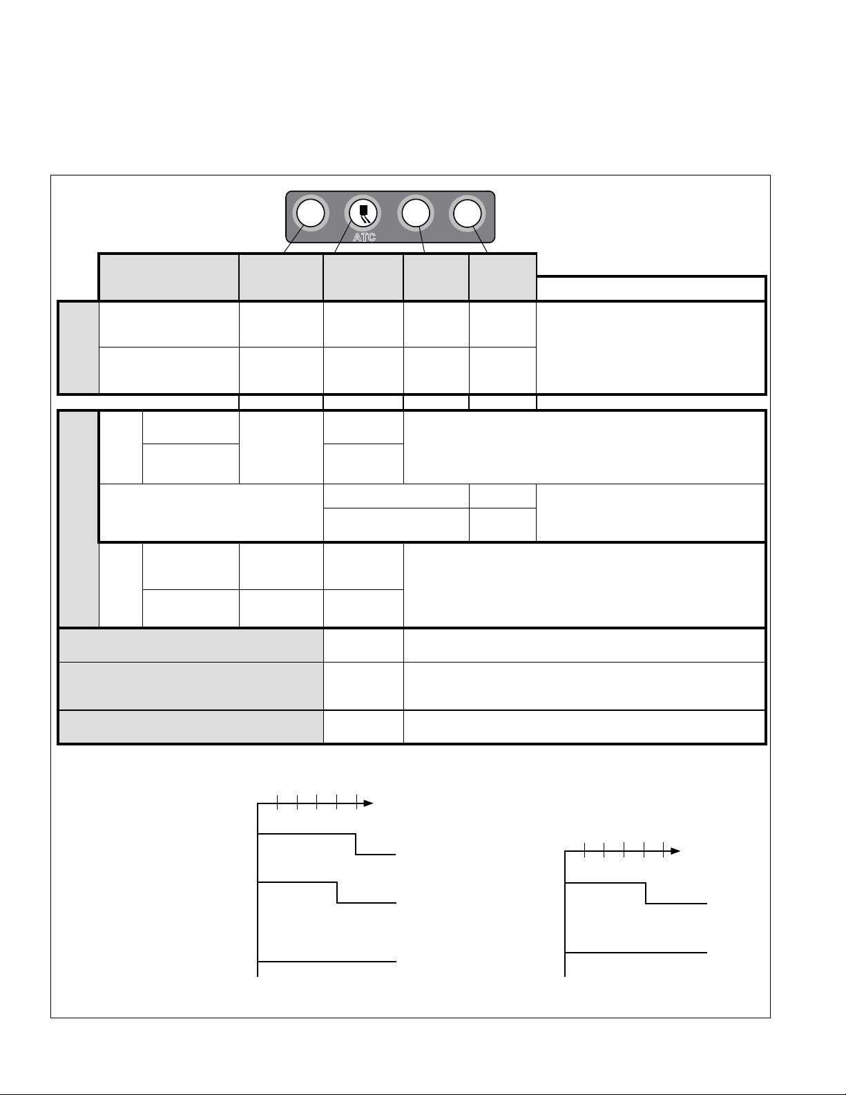
INDICATOR LAMPS AND POWER-UP
ATC
SEQUENCE
NOTICE: The vehicle operator should verify proper
operation of all installed indicator lamps (ABS, ATC/ESP,
and trailer ABS) when applying ignition power and during
vehicle operation. See Chart 2.
Lamps that do not illuminate as expected when ignition
power is applied, or remain illuminated, indicate the need
for maintenance.
Dash Lamps
Mode
Ignition on - start up
(trailer with PLC)
3 seconds after ignition
Start Up
At Vehicle
During an Automatic Traction Control (ATC) Event
(with no Diagnostic
Trouble Codes)
ABS
Off-
Road
Mode
Vehicles with the Hill Start Feature
Deep
Special Mode Operation
Mud/
Snow/
Mode
During Dynamometer Mode
Normal
During an ATC
Event
(“Hill Start Assist”)
Normal Off
During an ATC/
ESP Event
During an ESP Event
seconds*
Lamp Off* Lamp Off* Lamp Off* Lamp Off*
Lamp ashes
slowly (every
2.5 seconds)
ABS
ABS
Lamp
On for 3
Off
TRLR
ATC/ESP
Lamp
On for 2.5
seconds*
Lamp OFF
Flashes
quickly
During HSA Event Lamp OFF
HSA Manually Disabled
Flashes
slowly (every
2.5 seconds)
Flashes
quickly
Flashes
quickly
Lamp ON
(ATC
Disabled)
Flashes
quickly
On for 3
seconds**
•
HSA
Trailer
ABS
Lamp
• Uses dash switch
• Not for rm road surfaces
• Allows more wheel lock-up (less ABS intervention)
• Mode only applies under 25 mph (Over 25 mph, the system reverts
to full ABS — including ATC/ESP — and lamp goes off.)
• Uses dash switch
• Increases allowable wheel slip during ATC interventions
• Not for rm road surfaces
• Reduces wheel slip during acceleration at low speeds
• Disables ATC monitoring functions
• When not in Dynamometer Mode, an illuminated lamp indicates an
ATC trouble code is present
System intervenes to reduce the risk of rollovers, loss-of-control, etc.
HSA
Lamp
On for 3
seconds
Flashes
slowly
Comments
*If any of the described lamp behaviors do
not occur — or if the lamp remains on during
operation — have the vehicle serviced by a
qualied mechanic as soon as possible to
restore full system functionality.
Lamp remains ON if HSA DTC is present
Power
ABS System
Application
Status Indicators
at Start-Up
Powered Vehicle ABS
Indicator Lamp
Trailer ABS
Indicator Lamp
(PLC Detected)**
Trailer ABS Indicator
Lamp**
(PLC Not Detected)
*Some vehicle manufacturers may illuminate the trailer ABS indicator lamp at power-up regardless of whether a
PLC signal is detected from the trailer or not. Consult the vehicle manufacturer’s documentation for more details.
CHART 2 - BENDIX® EC-60™ INDICATOR LAMP BEHAVIOR
8
0.5 2.0 2.5 3.0 (sec.)1.5
ON
OFF
ON
OFF
ON
OFF
ATC/ESP System
Status Indicator
at Start-Up
ATC/ESP
enabled
No ESP
or ATC
0.5 2.0 2.5 3.0 (sec.)1.5
ON
OFF
ON
OFF
Power
Application

ABS Indicator Lamp Operation (Bulb Check)
The ECU will illuminate the ABS Indicator Lamp for
approximately three seconds when ignition power is
applied, after which the lamp will extinguish if no diagnostic
trouble codes are detected.
The ECU will illuminate the ABS Indicator Lamp whenever
full ABS operation is not available due to a diagnostic
trouble code. In most cases, partial ABS is still available.
ATC/ESP Status/Indicator Lamp Operation
The ECU will illuminate the ATC/ESP lamp for approximately
2.5 seconds when ignition power is applied, after which the
lamp will extinguish, if no diagnostic trouble codes are
detected. The ECU will continuously illuminate the ATC/
ESP Indicator Lamp whenever ESP or ATC is disabled due
to a diagnostic trouble code.
During an ESP or ATC intervention, the lamp will ash
rapidly (2.5 times per second). When the ECU is placed
in the ATC Mud/Snow (off-road) mode, the lamp will ash
slowly at a rate of once every 2.5 seconds.
Trailer ABS Indicator Lamp Operation
The ECU will control the Trailer ABS Indicator Lamp
when a PLC signal (SAE J2497) from a trailer ABS ECU
is detected.
Hill Start Assist (HSA) Indicator Lamp Operation
Vehicles with HSA enabled, will illuminate the HSA Indicator
Lamp when ignition power is applied, after which the lamp
will extinguish if there are no issues with the HSA system.
ECUCongurationTest
Within two seconds of the application of ignition power, the
ECU will perform a test to detect system conguration with
regards to the number of wheel speed sensors and PMVs.
This can be audibly detected by a rapid cycling of the PMVs.
(Note: The ECU will not perform the conguration test when
wheel speed sensors show that the vehicle is in motion.)
Pressure Modulator Valve and Traction Control
Valve Chuff Test
Right Steer
Driver
Left Steer
FIGURE 9 - VEHICLE ORIENTATION (TYPICAL)
After the performance of the conguration test, the Bendix®
EC-60™ controller will perform a Bendix-patented PMV
and TCV Chuff Test. The Chuff Test is an electrical and
Right Drive
Left Drive
Right
Additional
Left
Additional
pneumatic PMV test that can assist maintenance personnel
in verifying proper PMV wiring and installation.
When ignition power is applied, each modulator solenoid
is briey energized. If the air system is fully charged and
the service brake pedal is depressed during ignition, the
modulator creates a single, sharp audible “chuff” of air
pressure. The modulators are energized in a certain
pattern, as follows: right front, left front, right rear, left rear.
This test is performed only when the vehicle is stationary
(if the vehicle moves the chuff test will not be performed).
The Bendix EC-60 controller will perform a PMV chuff test
on all installed modulators in the following order:
• Steer Axle Right PMV
• Steer Axle Left PMV
• Drive Axle Right PMV
• Drive Axle Left PMV
• Additional Axle Right PMV
• Additional Axle Left PMV
• Drive Axle TCV
The pattern will then repeat itself.
If equipped with a Bendix EC-60 advanced controller,
following the completion of the second round of PMV &
TCV chuff tests, the controller (if congured to do so) will
perform a test to cross-check the trailer PMV operation with
the vehicle stop lamps. If the trailer PMV circuit is mis-wired
(including the steer axle TCV), the PMV will exhaust a large
amount of air, or none at all.
NOTICE: If there are any active Diagnostic Trouble Codes,
the stop lamp cross-check portion of the chuff test will
not be carried out until all DTCs are fully diagnosed and
corresponding repairs are successfully conducted. The
ESP/ATC dash indicator will also be illuminated when there
are active ABS, ATC or ESP DTCs.
The ECU will not perform the PMV Chuff Test when wheel
speed sensors show that the vehicle is in motion.
ABS OPERATION
Bendix® ABS uses wheel speed sensors, ABS pressure
modulator valves, and an ECU to control either four or six
wheels of a vehicle. The Bendix EC-60 controller monitors
individual wheel turning motion during braking and adjusts
or modulates the brake pressure at the wheel end. When
excessive wheel slip, or wheel lock-up is detected, the
Bendix EC-60 controller will activate the pressure modulator
valves to automatically reduce the brake pressure at one
or more of the wheel ends. By these actions, the ABS
system helps to maintain the vehicle's lateral stability and
steerability during heavy brake applications and during
braking on slippery surfaces.
9

Steer Axle Control
Although both wheels of the steer axle have their own wheel
speed sensor and pressure modulator valve, the Bendix
EC-60 controller blends the applied braking force between
the two steering axle brakes. This Bendix patented brake
application control, called Modied Individual Regulation
(MIR), is designed to help reduce steering wheel pull
during an ABS event on road surfaces with poor traction
(or areas of poor traction, e.g. asphalt road surfaces with
patches of ice).
Single Drive Axle Control (4x2 Vehicle)
For vehicles with a single rear drive axle (4x2), the brakes
are operated independently by the Bendix EC-60 controller,
based on the individual wheel behavior.
DualDriveAxleControl(4S/4MConguration)
For vehicles with dual drive axles (6x4) using a 4S/4M
conguration, one ABS modulator controls both right-side
rear wheels and the other modulator controls both left-side
rear wheels. Both wheels on each side receive equal
brake pressure during an ABS stop. The rear wheel speed
sensors must be installed on the axle with the lightest load.
DualRearAxleControl(6S/6MConguration)
For vehicles with dual rear axles (6x4, 6x2) using a 6S/6M
conguration, the rear wheels are controlled independently.
Therefore, brake application pressure at each wheel is
adjusted according to the individual wheel behavior on
the road surface.
6x2Vehicleswith6S/5MConguration
6x2 vehicles can utilize a 6S/5M conguration, with the
additional axle (a non-driven rear axle) having two sensors,
but only one Pressure Modulator Valve. In this case, the
PMV controls both wheels on the additional axle. The
additional axle wheels would receive equal brake pressure,
based on the wheel that is currently experiencing the most
wheel slip.
Normal Braking
During normal braking, brake pressure is delivered through
the ABS PMV and into the brake chamber. If the ECU
does not detect excessive wheel slip, it will not activate
ABS control, and normal vehicle service braking is applied.
Retarder Brake System Control
On surfaces with low traction, application of the retarder can
lead to high levels of wheel slip at the drive axle wheels,
which can adversely affect vehicle stability.
To prevent this, the Bendix® EC-60™ controller switches
off the retarder as soon as a lock-up is detected at one (or
more) of the drive axle wheels.
When the ECU is placed in the ABS off-road mode (on
vehicles equipped with this optional feature), it will switch
off the retarder only when ABS is active on a steer axle
wheel and a drive axle wheel.
Optional ABS Off-Road Mode
On some road conditions, particularly when the driving
surface is soft, the stopping distance with conventional
ABS may be longer than without ABS. This can occur
when a locked wheel on soft ground or loose gravel plows
up the road surface in front of the tire, changing the rolling
friction value. Although vehicle stopping distance with a
locked wheel (in the absence of ABS) may be shorter than
corresponding stopping distance with conventional ABS
control, vehicle steerability and stability would be reduced.
Advanced Bendix EC-60 controllers have an optional dash
switch that initiates a modied ABS control mode (know
as "off-road ABS") that more effectively accommodates
these soft road conditions to shorten stopping distance
while maintaining optimal vehicle steerability and stability.
Note: Off-road mode is not available if the vehicle is
equipped with Hill Start Assist (HSA).
WARNING: The ABS off-road mode should not
be used on normal, paved road surfaces because
vehicle stability and steerability may be reduced. The
ABSIndicatorLampwillashslowlytoindicatetothe
driver that the ABS off-road mode is engaged.
CAUTION: When ABS off-road mode is engaged,
stability functions are disabled at speeds below
approximately 25 mph. The ATC/ESP dash lamp will
illuminate to indicate to the driver that the stability
system is disabled.
The vehicle manufacturer should provide the optional ABS
off-road function only for vehicles that operate on unpaved
surfaces or that are used in off-road applications, and is
responsible for ensuring that vehicles equipped with the
ABS off-road function meet all FMVSS-121 requirements
and have adequate operator indicators and instructions.
The vehicle operator activates the off-road function with a
switch on the dash panel. A ashing ABS Indicator Lamp
indicates to the driver that the ABS off-road function is
engaged. To exit the ABS off-road mode, depress and
release the switch. A new ignition cycle will also cause
the ECU to exit the ABS off-road mode.
All-Wheel Drive (AWD) Vehicles
AWD vehicles with an engaged interaxle differential (steer
axle to rear axle)/AWD transfer case may have negative
effects on ABS performance. Optimum ABS performance
is achieved when the lockable differentials are disengaged,
allowing individual wheel control.
Advanced Bendix EC-60 controllers can be programmed
specically for this conguration to control the differential
lock/unlock solenoid in the AWD transfer case. When
programmed to do so, the ECU will disengage the locked
interaxle/AWD transfer case during an ABS event and
reengage it once the ABS event has ended.
10

ATC OPERATION
ATC Functional Overview
Just as ABS improves vehicle stability during braking,
ATC improves vehicle stability and traction during vehicle
acceleration. The Bendix EC-60 controller ATC function
uses the same wheel speed information and modulator
control as the ABS function. The Bendix EC-60 controller
detects excessive drive wheel speed, compares the speed
to the front, non-driven wheels, and reacts to help bring the
wheel spin under control. The controller can be congured
to use engine torque limiting and/or differential braking to
control wheel spin. For optimal ATC performance, both
methods are recommended.
ATC/ESP Lamp Output/ATC Mud/Snow Switch
Input
Advanced ECUs control the ATC/ESP dash lamp as
follows.
The ATC/ESP dash lamp illuminates:
1. During power up (e.g. when the vehicle is started) for
approximately 2.5 seconds and turns off after the self
test is completed, providing no diagnostic trouble codes
are present.
2. When ESP or ATC is disabled for any reason.
3. During an ESP or ATC event (the lamp will ash rapidly
at a rate of 2.5 times per second).
4. When the ECU is placed in the ATC off-road mode
(the lamp will ash steadily at a rate of once per 2.5
seconds). This noties the vehicle operator that the
ATC Mud/Snow mode is active.
5. When the ECU is placed in the ABS off-road mode.
When in this mode, ESP will be disabled below 25 mph
and its inactive status will be indicated by a steadily
illuminated ATC/ESP lamp.
Differential Braking
Differential braking within ATC is automatically activated
when drive wheel(s) on one side of the vehicle are spinning
excessively, which typically occurs on road surfaces
with patches of ice. The traction system will then lightly
apply the brake to the drive wheel(s) that are spinning
excessively. The vehicle differential will then drive the
wheels on the other side of the vehicle.
Differential braking (as part of ATC functionality) is available
at vehicle speeds up to 25 MPH.
Disabling ATC Differential Braking
ATC differential braking is disabled under the following
conditions:
1. During power up (e.g. when the vehicle is started), until
the ECU detects a service brake application.
2. If the ECU receives a J1939 message indicating that
the vehicle is parked.
3. When the dynamometer test mode is active. The
dynamometer test mode is entered using the diagnostic
blink code switch or by using a diagnostic tool (such as
Bendix
4. In response to a serial communications request from
a diagnostic tool.
5. If ATC Differential Braking function is activated for a long
time period to avoid overheating of the brakes. It would
take approximately 3 continuous minutes of activation
for the timeout to occur. Once timed out, approixmately
2 minutes of "cool off" time would be required before
ATC Differential Braking can be used again.
6. When certain diagnostic trouble code conditions are
detected.
®
ACom® Diagnostics).
Engine Torque Limiting with Smart ATC™
Traction Control
The Bendix EC-60 controller uses Engine Torque Limiting
to control drive axle wheel slip. This is communicated to
the engine control module (using J1939), and is available
at all vehicle speeds.
Bendix® Smart ATC™ Traction Control
The Bendix EC-60 controller has an additional feature
known as Smart ATC™ traction control. Smart ATC™
traction control monitors the accelerator pedal position
(using J1939) to help provide optimum traction and vehicle
stability. By determining the driver’s throttle input and
adapting the target slip of the drive wheels to the driving
situation, the Smart ATC™ traction control allows higher
wheel slip when the accelerator pedal is applied above a
preset level.
The wheel slip allowed by Smart ATC™ is decreased when
driving through a curve for improved stability.
Disabling ATC Engine Control and Smart ATC™
Traction Control
ATC Engine Control and Smart ATC™ traction control will
be disabled under the following conditions:
1. In response to a serial communications request from
an off-board tool.
2. At power-up until the ECU detects a service brake
application.
3. If the ECU receives a J1939 message indicating that
the vehicle is parked.
4. If the dynamometer test mode is active. This may be
accomplished via an off-board tool or the diagnostic
blink code switch.
5. When certain diagnostic trouble code conditions are
detected.
11
Optional ATC Mud/Snow (Off-Road) Mode
In some road conditions, the vehicle operator may desire
additional drive wheel slip when ATC is active. The
Advanced Bendix EC-60 controller has an optional control
mode to permit this desired performance.
The vehicle operator can activate the Mud/Snow function
with a switch on the dash panel. Alternately, a J1939
message may be used to place the vehicle in this mode.
The ATC/ESP Indicator Lamp will ash steadily at a rate
of once every 2.5 seconds to conrm that the ATC mud/
snow mode is engaged.
To exit the ATC Mud/Snow mode, depress and release the
ATC Mud/Snow switch.
ADVANCED ABS WITH STABILITY
CONTROL
Overview
ESP stability system reduces the risk of rollovers,
jackkning and other loss-of-control events. ESP features
include Roll Stability Program (RSP) and Yaw Control.
During operation, the ECU of the Bendix Advanced ABS
system constantly compares performance models to the
Drag Torque Control Functional Overview
Advanced Bendix® EC-60™ controllers have a feature
referred to as drag torque control which reduces wheel slip
on a driven axle due to driveline inertia. This condition is
addressed by increasing the engine torque to overcome
the inertia.
Drag torque control increases vehicle stability on lowtraction road surfaces during down-shifting or retarder
braking.
vehicle’s actual movement, using the wheel speed sensors
of the ABS system, as well as lateral, yaw, and steering
angle sensors. If the vehicle shows a tendency to leave
an appropriate travel path, or if critical threshold values are
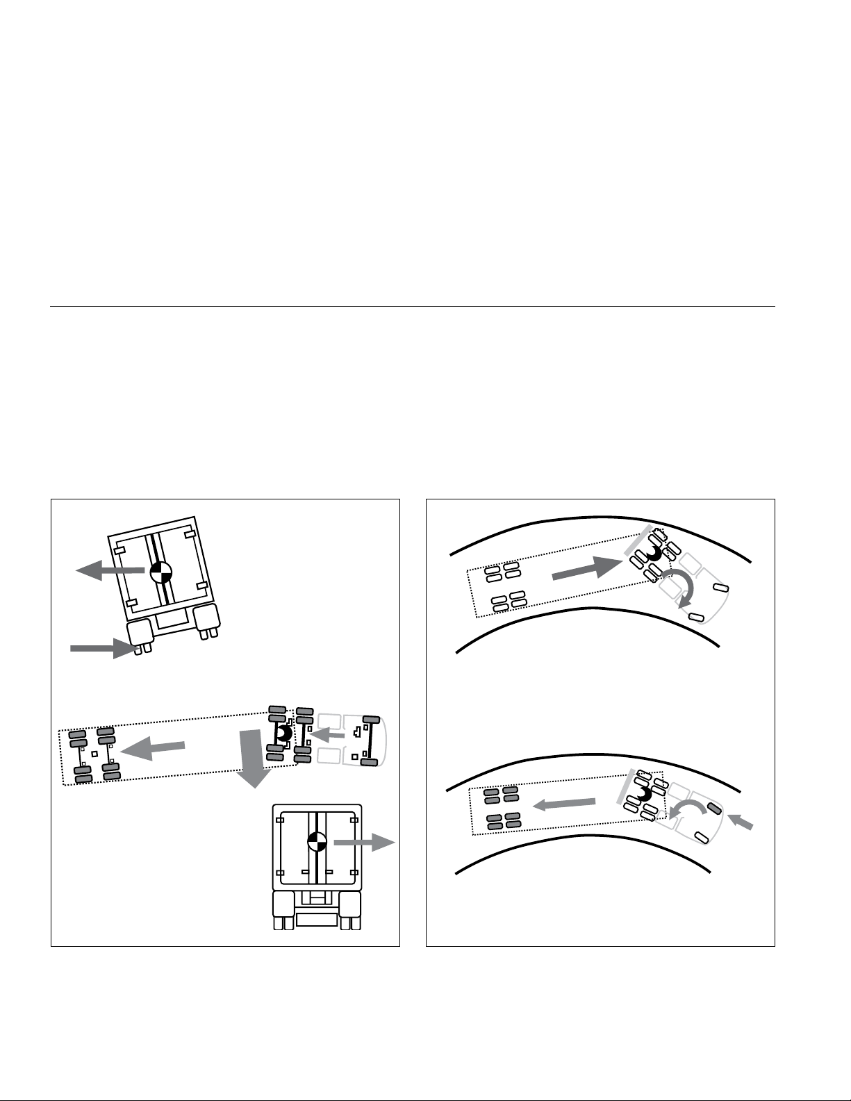
approached, the system will intervene to assist the driver.
A Real World Example
Of How The RSP
System Operates:
Excessive speed for road
conditions creates forces
that exceed the threshold
at which a vehicle is likely
to rollover on a higherfriction surface.
The system automatically reduces
engine torque and applies the
service brakes (based on the
projected rollover risk) to reduce
the vehicle speed, thereby
reducing the tendency to roll over.
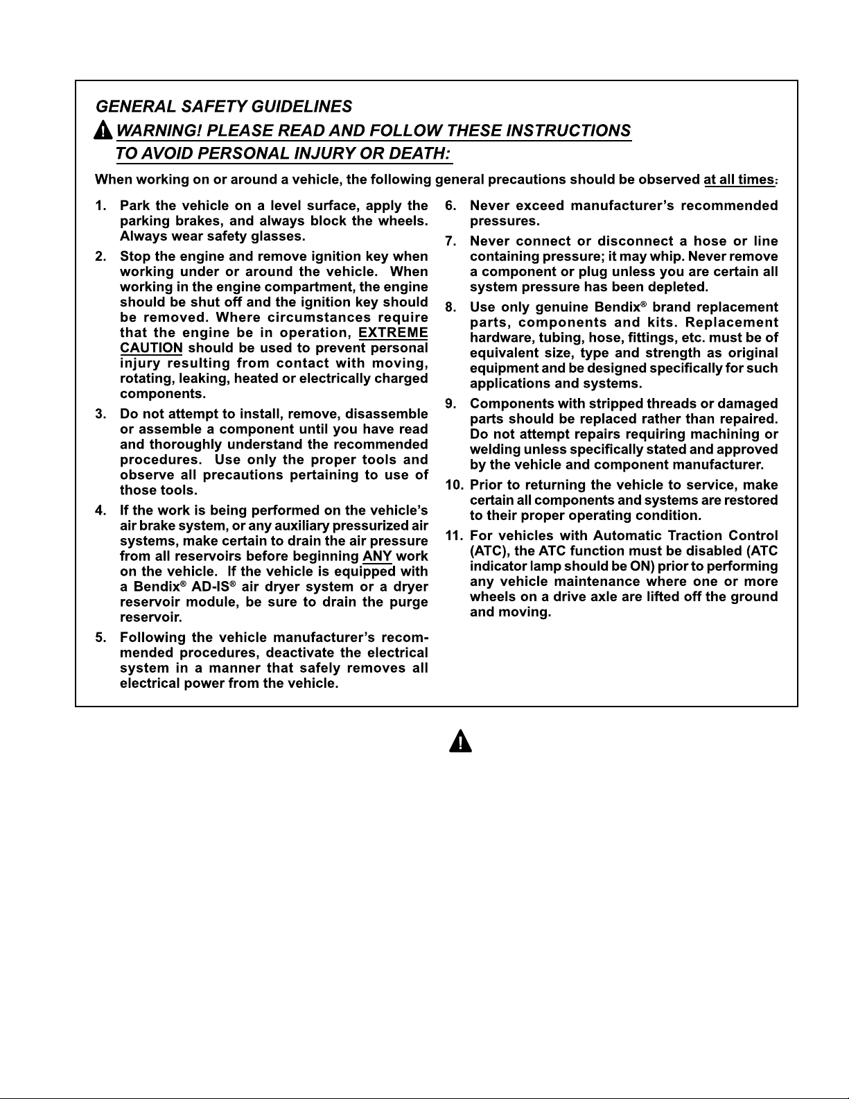
A Real World Example Of How Yaw Control
Operates:
Excessive speed exceeds the threshold, creating a
situation where a vehicle is likely to spin and jackknife.
®
The Bendix
and selectively applies brakes to reduce the tendency
to jackknife.
Yaw Control system reduces engine throttle
FIGURE 11 - RSP EXAMPLE
12
FIGURE 12 - YAW CONTROL EXAMPLE

Roll Stability Program
Bendix RSP, an element of the overall ESP system,
addresses rollover conditions. In the case of a potential
roll event, the ECU will override the throttle and quickly
apply brake pressure at all wheel ends to slow the vehicle
combination. The level of braking application during an
RSP event will be proportional to roll risk. See Figure 11.
Yaw Stability
Yaw stability counteracts the tendency of a vehicle to spin
about its vertical axis. During operation, if the friction
between the road surface and the tires is not sufcient
to oppose lateral (side) forces, one or more of the tires
can slide, causing the truck/tractor to spin. These events
are referred to as either an "under-steer" situation (where
there is a lack of vehicle response to steering input due to
tire slide on the steer axle) or an "over-steer" (where the
tractor's rear end slides out due to tire slide on the rear axle)
situation. Generally, shorter wheelbase vehicles (tractors,
for instance) have less natural yaw stability, while longer
wheelbase vehicles (straight trucks, for instance) have
greater natural yaw stability. Factors that inuence yaw
stability are: wheelbase, suspension, steering geometry,
weight distribution front to rear, and vehicle track width.
Yaw Control
Yaw Control responds to a wide range of low- to highfriction surface scenarios including rollover, jackknife
and loss-of-control. It is the recommended system for all
power vehicles and especially critical for tractors pulling
trailers. In the case of vehicle slide (over-steer or understeer situations), the system will reduce the throttle and
then brake one or more of the “four corners” of the vehicle
(in addition to potentially applying the trailer brakes), thus
applying a counter-force to better align the vehicle with an
appropriate path of travel.
For example, in an over-steer situation, the system applies
the “outside” front brake; while in an under-steer condition,
the “inside” rear brake is applied. (See Figure 12)
IMPORTANT SAFETY INFORMATION
ABOUT THE BENDIX® ESP® STABILITY
SYSTEM
ESP May Reduce The Vehicle Speed
Automatically
ESP can make the vehicle decelerate automatically. ESP
can slow the vehicle with or without the operator applying
the brake, and even when the throttle is being applied.
CAUTION
To minimize unexpected deceleration and reduce the risk
of a collision the operator must:
• Avoid aggressive driving maneuvers, such as sharp
turns or abrupt lane changes at high speeds, which
might trigger the stability system.
• Always operate the vehicle safely, drive defensively,
anticipate obstacles and pay attention to road, weather
and trafc conditions. ABS, ATC and ESP stability
systems are no substitute for prudent, careful driving.
Towing Doubles Or Triples May Reduce The
Effectiveness Of Stability Systems
ESP is designed and optimized for trucks and for tractors
that tow single trailers. If a tractor equipped with ESP
is used to power multiple trailer combinations (known
as “doubles” or “triples”) the effectiveness of the ESP
system may be greatly reduced. Extremely careful
driving is always required when towing doubles or triples.
Excessive speed and aggressive maneuvers, such as
sharp turns, sudden steering inputs or abrupt lane changes
should be avoided.
Limitations Of Stability Systems
The ESP stability system’s effectiveness may be greatly
reduced if:
• The load shifts due to improper retention, accident
damage or the inherently mobile nature of some loads
(for example, hanging meat, live animals or partially
laden tankers),
• The vehicle has an unusually high or off-set center of
gravity (CG),
• One side of the vehicle drops off the pavement at an
angle that is too large to be counteracted by a reduction
in speed,
• The vehicle is used to haul double or triple trailer
combinations,
• If very rapidly winding steering inputs are inputted at
high speeds,
• There are mechanical problems with suspension
leveling of the tractor or trailer resulting in uneven loads,
• The vehicle is maneuvering on a high banked road
creating either additional side forces due to the weight
(mass) of the vehicle or a deviation between expected
& actual yaw rates,
• Gusty winds are strong enough to cause signicant
side forces on the vehicle and any towed vehicles.
To Maximize The Effectiveness Of ESP:
• Loads must be properly secured at all times.
• Drivers need to exercise extreme caution at all times,
and avoid sharp turns, sudden steering inputs or abrupt
lane changes at high speeds, particularly if:
› the vehicle hauls loads that could shift,
› the vehicle or load has a high or off-set center of
gravity (CG) when loaded, or
› the vehicle tows doubles or triples.
13

TruckChassisModications
If the vehicle’s chassis components are altered (for example,
a wheel base extension or reduction, tag axle addition
or removal, a major body change such as conversion of
a tractor into a truck, or an axle, suspension, or steering
system component modication) the Bendix® ESP® system
must be disabled. Have a qualied mechanic replace the
Advanced EC-60 ECU with a Premium EC-60 ECU and
secure the X4 connector which will no longer be used. The
ATC/ESP indicator lamp would continue to function as an
ATC indicator lamp, and should be designated as ATC only.
WARNING:Ifamodiedvehicledoesnothave
the ESP system disabled, serious vehicle braking
and performance issues could result, including
unnecessary ESP system interventions. This can
lead to a loss-of-control of the vehicle. In addition,
remove all cab signage (e.g. visor labels, etc.) used
to show that Bendix ESP was installed and make any
necessary notations in the vehicle manual(s), so that
drivers do not misunderstand which ABS options are
installed on the vehicle.
SensorLocationModications
The location and orientation of the Steering Angle Sensor
and Yaw Rate Sensor must not be altered. When servicing,
an identical component must be used in the same
orientation (using OEM brackets & torque requirements).
During installation follow the OEM leveling guidelines.
Steering Angle Sensor Re-Calibration
Whenever maintenance or repair work is performed to the
steering mechanism, linkage, steering gear, adjustment of
the wheel track, or if the steering angle sensor is replaced,
a recalibration of the Steering Angle Sensor must be
performed.
WARNING! If the Steering Angle Sensor is not
recalibrated, the yaw control system may not function
properly, which can result in incidents leading to loss
of vehicle control. See page 19 of this document for
more details on this procedure.
DYNAMOMETER TEST MODE
CAUTION: ATC and ESP must be disabled prior
to conducting any dynamometer testing. When the
Dynamometer Test Mode is engaged, ATC brake control
and engine control along with drag torque control and ESP
are turned off. This test mode is used to avoid torque
reduction or torque increase and brake control activation
when the vehicle is operated on a dynamometer for testing
purposes.
The Dynamometer Test Mode may be activated by pressing
and releasing the diagnostic blink code switch ve times or
by using a hand-held or PC-based diagnostic tool.
During Dynamometer Test Mode the ATC lamp remains ON.
Advanced Bendix
in the Dynamometer Test Mode even if power to the ECU
is removed and re-applied. To exit the test mode, press
and release the blink code switch three times, or use a
hand-held or PC-based diagnostic tool.
®
EC-60™ Contollers will remain engaged
AUTOMATIC TIRE SIZE CALIBRATION
The ECU requires a precise rolling circumference ratio
between steer axle and drive axle tires in order for ABS,
ATC, and ESP to perform in an optimal manner. For this
reason, a continuously monitoring process takes place
in which the precise ratio is calculated. This calculated
value is stored in the ECU memory provided the following
conditions are met:
1. Rolling-circumference ratio is within the permissible
range.
2. Vehicle speed is greater than approximately 12 MPH.
3. No acceleration or deceleration is taking place.
4. There are no active speed sensor diagnostic trouble
codes.
The ECU is provided with a ratio value of 1.00 as a default
setting. If the automatic tire size alignment calculates a
different value, this is used to overwrite the original gure
in the memory. This process adapts the ABS and ATC
function to the vehicle.
14
Acceptable Tire Sizes
The speed calculation for an exciter ring with 100 teeth is
based on a default tire size of 510 revolutions per mile.
This gure is based on the actual rolling circumference of
the tires, which varies with tire size, tire wear, tire pressure,
vehicle loading, etc.
The ABS response sensitivity is reduced when the actual
rolling circumference is excessive on all wheels. For a 100
tooth exciter ring, the minimum number of tire revolutions
per mile is 426, and the maximum is 567. The ECU will
set diagnostic trouble codes if the number of revolutions
is out of this range.

In addition, the size of the steer axle tires compared to
the drive axle tires also has to be within the ABS system
design. To avoid diagnostic trouble codes, the ratio of the
effective rolling circumference of the steer axle, divided by
the effective rolling circumference of the drive axle, must
be between 0.85 to 1.15.
ATC Modulator Diagnostic Trouble Code
ATC and ESP are disabled. ABS remains active.
J1939 Communication Diagnostic Trouble Code
ATC and ESP are disabled. ABS remains active.
CAUTION: The ESP system effectiveness relies
on the accuracy of vehicle speed. If a major change
on the tire sizes occurs such that the odometer setting
needs to be changed, the Advanced ABS controller's
setting of tire sizes must be reprogrammed to new
valuesatthesametimebyacertiedmechanic.
SYSTEM IMPACT DURING ACTIVE
TROUBLE CODES
ABS PARTIAL SHUTDOWN
Depending on which component the trouble code is
detected, the ABS, ATC, and ESP functions may be fully
or partially disabled. Even with the ABS indicator lamp
illuminated, the Bendix EC-60 controller may still provide
ABS function on wheels that are not affected. The ABS
system controller should be serviced as soon as possible.
Steer Axle ABS Modulator Diagnostic Trouble
Code
ABS on the affected wheel is disabled. ABS and ATC on
all other wheels remains active. ESP is disabled.
Drive Axle/Additional Axle ABS Modulator
Diagnostic Trouble Code
ATC is disabled. ABS on the affected wheel is disabled.
ABS on all other wheels remains active. ESP is disabled.
Steer Axle Wheel Speed Sensor Diagnostic
Trouble Code
The wheel with the diagnostic trouble code is still controlled
by using input from the remaining wheel speed sensor on
the steer axle. ABS remains active on the rear wheels.
ATC and ESP are disabled.
ECU Diagnostic Trouble Code
ABS, ATC, and ESP are disabled. The system reverts to
normal braking.
Voltage Diagnostic Trouble Code
While voltage is out of range, ABS, ATC, and ESP are
disabled. The system reverts to normal braking. When
the correct voltage level is restored, full ABS and ATC
function is available. The operating voltage range is 9.0
to 17.0 VDC for 12 volt systems, and 20 to 33.5 volts for
24 volt systems.
Steering Angle Sensor Diagnostic Trouble Code
ESP is disabled. ABS and ATC remain active.
Yaw Rate/Lateral Acceleration Sensor
Diagnostic Trouble Code
ESP is disabled. ABS and ATC remain active.
Brake Demand Pressure Sensor Diagnostic
Trouble Code
ESP is disabled. ABS and ATC remain active.
Load Sensor Diagnostic Trouble Code
ESP is disabled. ABS and ATC remain active.
Steer Axle TCV Diagnostic Trouble Code
ESP is disabled. ABS and ATC remain active.
Trailer PMV Diagnostic Trouble Code
ESP is disabled. ABS and ATC remain active.
Drive Axle/Additional Axle Wheel Speed Sensor
Diagnostic Trouble Code
ATC and ESP are disabled. In a four sensor system, ABS
on the affected wheel is disabled, but ABS on all other
wheels remains active.
In a six sensor system, ABS remains active by using input
from the remaining rear wheel speed sensor on the same
side.
15

SYSTEM RECONFIGURATION
The Bendix® EC-60™ controller is designed to allow the
technician to change the default system settings (chosen
by the vehicle OEM) to provide additional or customized
features.
Depending on the model, the customizable features include
ABS control settings, engine module communication etc.
Many of these settings can be recongured using a hand-
held or PC-based software, such as the Bendix
Diagnostics program.
®
ACom®
ECU RECONFIGURATION
Reconguring a Bendix EC-60 controller may be carried
out by using the Blink Code Switch or by using a hand-held
or PC-based diagnostic tool.
Note: During the reconguration process, and independently
from any reconguration being carried out by the technician,
the ECU will automatically check the J1939 serial link and
communicate with other vehicle modules. In particular, if
the serial link shows that the vehicle has a retarder device
present, the ECU will congure itself to communicate with
the retarder device for improved ABS performance. For
example, if the ECU detects the presence of a retarder
disable relay during a reconguration, it will congure
itself to control the relay to disable the retarding device
as needed.
RecongurationUsingtheBlinkCodeSwitch
With ignition power removed from the Bendix EC-60
controller, depress the blink code switch. After the ignition
power is activated, depress and release the switch seven
times to initiate a reconguration event.
Diagnostic Tool
A reconguration event may be initiated using a hand-held
or PC-based diagnostic tool to communicate with the ECU
over the SAE J1587 diagnostic link.
6S/5MConguration
Advanced Bendix® EC-60™ controllers will congure for
6S/5M operation when a reconguration event is initiated
and the ECU detects that an additional axle PMV is wired
as follows:
PMV Connector ECU Connector
Hold Right Additional Axle Hold
Release Left Additional Axle Release
Common Right Additional Axle Common
16
Troubleshooting: General
REMOVING THE BENDIX® EC-60™
CONTROLLER ASSEMBLY
1. Turn vehicle ignition off.
2. Remove as much contamination as possible prior to
disconnecting electrical connections.
3. Note the Bendix EC-60 controller assembly mounting
position on the vehicle.
4. Disconnect the electrical connectors from the Bendix
EC-60 controller.
5. Remove and retain the mounting bolts that secure the
Bendix EC-60 controller.
CAUTION
The VIN of the vehicle is stored in the ECU internal
memory, and is cross-checked by the ECU using
information obtained from other vehicle controllers.
If the VIN stored in the ECU does not match the VIN
obtained from the other vehicle controller, the ECU will
generate an ECU Internal VIN Mismatch DTC.
Accordingly, do not switch Advanced controllers from
one vehicle to another.
17

OBTAINING A NEW BENDIX EC-60
ADVANCED CONTROLLER
Should the Advanced Bendix EC-60 controller require
replacement, certain steps must be followed:
1. Record the vehicle model, VIN, year and date of
manufacture from the vehicle.
2. Record the part number of the Bendix EC-60 Advanced
Controller.
3. Provide this information to your local OEM vehicle
service department to obtain a new ECU. The OEM
service department will install the same parameter set
in the new controller that was loaded into the original
ECU at the vehicle OEM assembly facility.
INSTALLING A NEW BENDIX® EC-60™
CONTROLLER
CAUTION When replacing the Bendix EC-60
controller, verify with the OEM service department that the
unit you are installing has the correct parameter set. Failure
to do so could result in a loss of features or degraded ESP
performance.
For further information, contact either the vehicle
manufacturer, Bendix or your local authorized Bendix
dealer.
1. Position and secure the Bendix® EC-60™ controller in
the original mounting orientation using the mounting
bolts retained during removal. Use no more torque
than is necessary to rmly secure the ECU into position.
Over-tightening the mounting hardware can cause
damage to the EC-60™ controller.
2. Reconnect the electrical connectors to the EC-60™
controller.
3. Apply power and monitor the Bendix EC-60 controller
power-up sequence to verify proper system operation.
See Troubleshooting: Wiring section beginning on page
45 for more information on wire harnesses.
WARNING: Bendix ESP stability system is validated
with specic Bendix® brand components. Always use
Bendix® brand replacement parts to prevent compromising
system performance. Bendix is not able to validate the
safe and reliable use of substitute or alternate components
that may be available from other manufacturers. Further,
suppliers of a non-Bendix® brand ABS component may
implement design changes in their component (without the
knowledge or approval of Bendix) which could negatively
affect antilock system reliability and braking performance
issues.
REMOVAL OF THE STEERING ANGLE
SENSOR
Service Checks:
1. Check all wiring and connectors. Some installations
also include an intermediate connector from the
steering angle sensor to the main vehicle wire harness.
Make sure all connections are free from visible damage.
2. Examine the sensor. Make sure the sensor, its
mounting screws, and the interface between the hub
and the steering column are not damaged.
Diagnostics:
The steering angle sensor is only operational in conjunction
with an Advanced ABS ECU. No independent diagnostics
can be performed on the sensor.
Removal:
1. Remove steering column sheathing.
2. Depending upon manufacturer, the steering angle
sensor could be located either near the steering wheel,
necessitating the removal of the steering wheel, or
near the joint to the vehicle steering mechanism,
necessitating the disconnection of this linkage.
3. Unplug sensor cable assembly from body of sensor.
Squeeze the mounting tabs and pull gently on the
connector until it disengages.
4. Unscrew all three of the mounting screws that hold the
body of the sensor to the steering column body.
5. Slide the sensor over the column to remove. Take note
if the sensor label is facing upward or downward.
Installation:
1. Obtain a new sensor. The sensor is not repairable in
the eld.
2. Slide the sensor over the column. The center hub of the
sensor must be aligned with the corresponding notch
in the column. Different column manufacturers may
implement this hub alignment in different ways. The
sensor label should be facing in the same direction as
the removed sensor.
3. Assemble to column non-moving plate with three selflocking screws.
4. Tighten screws to steering column manufacturer's
recommended torque specication.
5. Reconnect the connector. Ensure that there will be no
force applied to the sensor because the connector is
pulling on the sensor body.
6. If the wire harness leading to the sensor is being
replaced, ensure that it is adequately tie wrapped
so that the full motion of the steering column can be
achieved without pulling apart the connectors.
7. Reinstall the column sheathing. The sensor is not
protected against dirt or water intrusion, so care
must be taken not to introduce these elements during
installation.
18
 Loading...